HanleyLED PHOENIXNRG STREAMLINER User manual


PHOENIXNRG STREAMLINER INSTALLATION GUIDE
2hanleyledsoluons.com | 800.542.9941
STREAMLINE YOUR INSTALLS
• Powered by Socket (PBS) retrot sign cabinet soluon where direct 120–277v input power is used.
• No power supply needed.
• Get in, get out. No power supply hookup, no messy wiring, no wire nuts... simply remove ballast, reconnect
primary power to sockets and pop in Streamliner Tubes.
• Superior engineered LED Extrusion Bar for added rigidity and less sagging.
• Versale for all applicaons where T12 Fluorescent Lamps are used.
• Premium HanleyLED quality with 7 year product warranty when used with Hanley Surge Protector.
• HanleyPRO Layout Creator at hanleyledsoluons.com.
READ THESE INSTRUCTIONS COMPLETELY AND CAREFULLY
STOP
Tools required:
Screwdriver Electric DrillTape Measure Wire Cuers
Components:
No Addional power supplies required.
Mounts direct to socket.
Streamliner Tube
Surge Protector SPD10277PW3511
Sold Separately
• 3-lead Surge Protector
• UL Recognized for Surge Protecon Devices
• Protects Against Surges According to IEC61643-11
• None Load Current
• 10KA and 10KV
• IP67 Rated for Wet locaons
• Parallel Wiring
PLG Exhibit 2053
Grimco, Inc. v. Principal Lighting Group, LLC
IPR2021-00968
Page 1
PHOENIXNRG STREAMLINER INSTALLATION GUIDE
3hanleyledsoluons.com | 800.542.9941
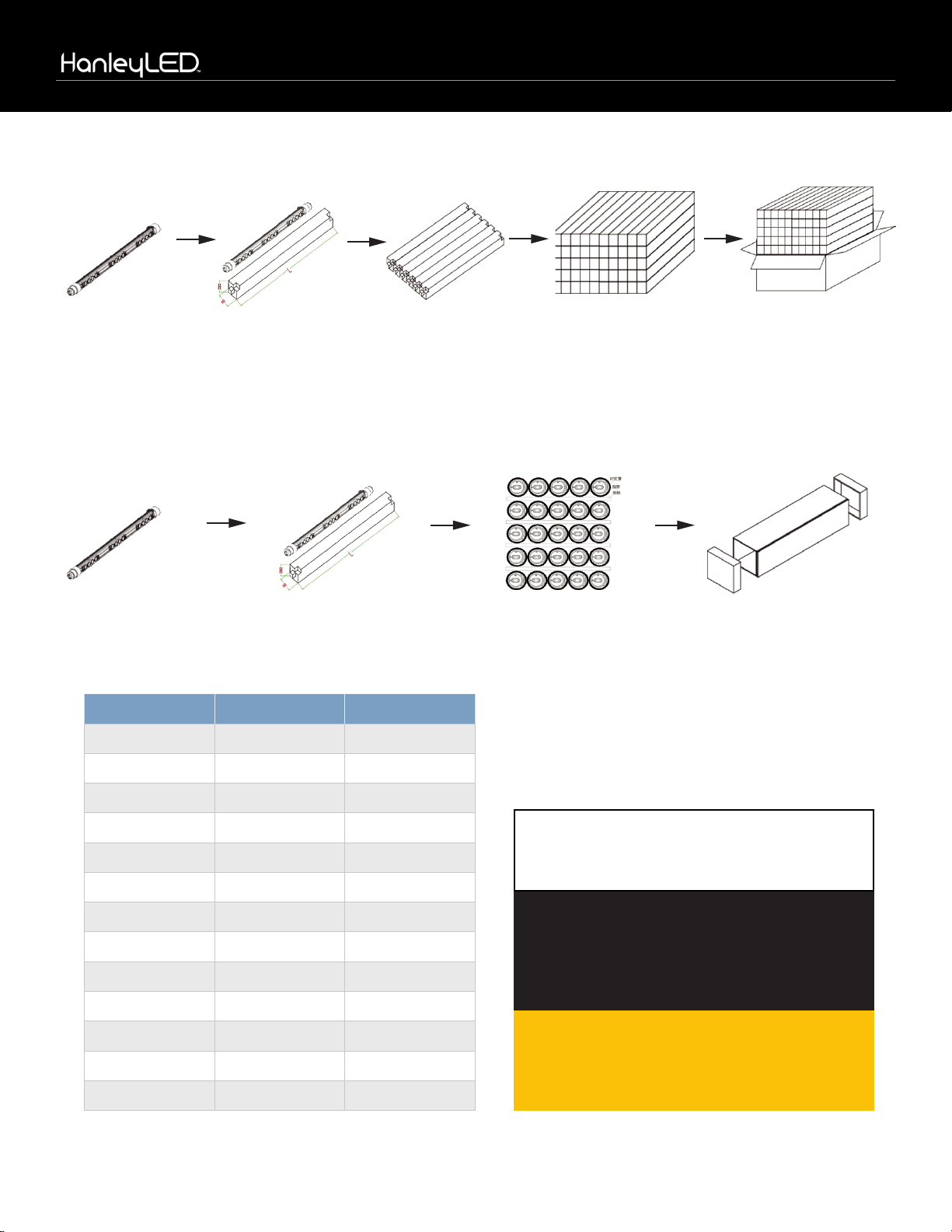
Packaging for tubes 72” and under
Streamliner Tube
Streamliner Tube
Streamliner Tube
in box
Streamliner Tube
in box
Boxes placed
in a case
10 Streamliner tubes per layer, 50 Tubes per case
Packaging for tubes 84” and larger
Boxes placed
in a case
5 Streamliner tubes per layer,
25 Tubes per case
Item Tubes per box Tubes per case
HPEB-SL2S24 150
HPEB-SL2S30 150
HPEB-SL2S36 150
HPEB-SL2S42 150
HPEB-SL2S48 150
HPEB-SL2S60 150
HPEB-SL2S64 150
HPEB-SL2S72 150
HPEB-SL2S84 125
HPEB-SL2S96 125
HPEB-SL2S108 125
HPEB-SL2S117 125
HPEB-SL2S120 125
NOTE: All materials removed must be disposed
of in accordance with applicable local, state,
and federal laws.
WARNING Check Polarity:
All connecons must be WHITE-TO-RED (+)
and BLACK-TO-BLACK (-). Reverse polarity
connecons may damage the LEDs and will void
product warranty.
Cauon: Turn o power to sign before inspecng
or removing exisng light source. Power must
remain o while installing the Concorde
Cabinet System.
PLG Exhibit 2053
Grimco, Inc. v. Principal Lighting Group, LLC
IPR2021-00968
Page 2

PHOENIXNRG STREAMLINER INSTALLATION GUIDE
4hanleyledsoluons.com | 800.542.9941
RETROFIT INSTALLATION GUIDE
PhoenixNRG Streamliner
This guide is designed to aid in the installaon of HanleyLED’s PhoenixNRG Streamliner. Skilled trades people
that are familiar with general construcon, electrical, and sign installaon techniques should do the installaon.
Licensed electricians should provide all installaon and hook-up of components. All installaon and hook-up
should be done in accordance with all Naonal and Local codes and permits. In no way is this document intended
to construe warranty or tness of use of the products described, nor is it intended to provide safety instrucon for
those installing the product.
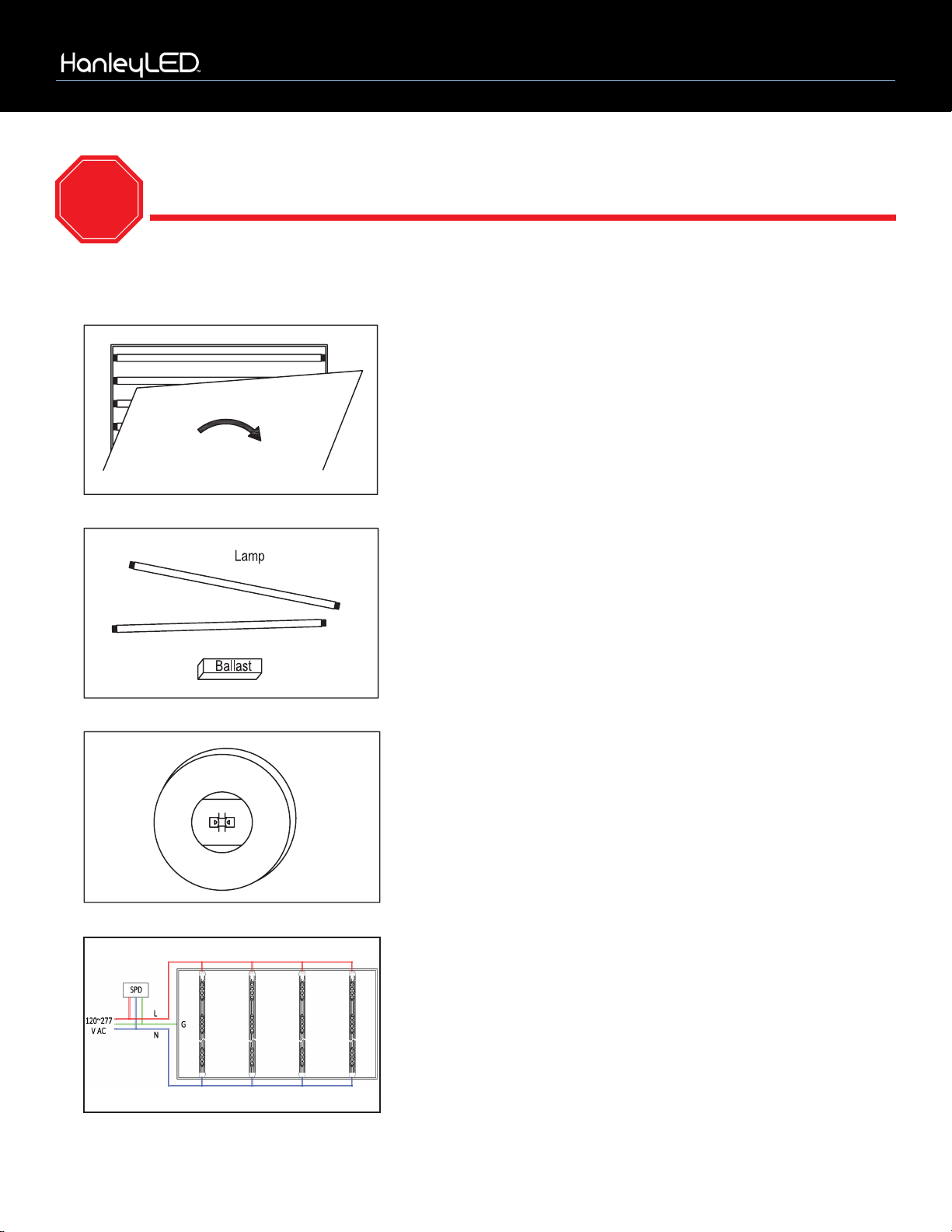
Prepping the Cabinet
Step 1
• Remove exisng neon or uorescent bulbs by having a licensed electrician disconnect and remove the neon
transformers or uorescent ballasts.
• Remove exisng neon and standos or uorescent lamps.
• Inspect all sockets for signs of damage.
• Replace any damaged sockets. Reconnect socket wires directly to primary power.
• Aach surge protector at this juncon of socket wires and primary wire.
NOTE: Power to the sign should sll be o at this stage.
Tools Required:
• Wire cuer & strippers
• Measuring tape
• Marking pens
• Drill
• Standard hardware and supplies in addion to the HanleyLED Streamliner installaon guides
(UL lisng may be required on certain items).
THE FIELD INSTALLATION OF THIS RETROFIT SYSTEM INTO A SIGN IS SUBJECT TO THE
ACCEPTANCE OF LOCAL INSPECTION AUTHORITY.
ALL MATERIALS REMOVED MUST BE DISPOSED OF IN ACCORDANCE WITH
APPLICABLE LOCAL, STATE AND FEDERAL LAWS.
CAUTION: TURN OFF POWER TO THE SIGN BEFORE INSPECTING OR REMOVING EXISTING LIGHT
SOURCE. THE POWER MUST REMAIN OFF WHILE INSTALLING THE LED RETROFIT KIT.
PLG Exhibit 2053
Grimco, Inc. v. Principal Lighting Group, LLC
IPR2021-00968
Page 3

PHOENIXNRG STREAMLINER INSTALLATION GUIDE
5hanleyledsoluons.com | 800.542.9941
Prepping the Cabinet Continued
Step 2
• Installer should examine all parts that are not intended to be replaced by the retrot kit for damage and
replace any damaged parts prior to installaon of the retrot kit.
• Do not make or alter any open holes in an enclosure of wiring or electrical components during kit installaon.
• Any exisng holes in the cabinet that will not be used in the installaon of product should be patched to
avoid water damage.
• Openings smaller than ½” diameter may be sealed with the appropriate amount of rated caulk or sealant.
Openings larger than ½” should be patched using an aluminum or zinc coated steel patch with rivets and sealant.
Step 3
Proceed with the PhoenixNRG Streamliner installaon guidelines.
PHOENIXNRG STREAMLINER DIMENSIONS
Your PhoenixNRG Streamliner is ready to come out of the package!
• Simply disconnect and remove the uorescent lamp ballast.
• Inspect sockets for damage (replace sockets if necessary).
• Reconnect sockets to primary power
• Pop Streamliners into sockets.
NO PEELING AND STICKING OF MODULES REQUIRED AND NO EXTERNAL POWER SUPPLY NEEDED!
PLG Exhibit 2053
Grimco, Inc. v. Principal Lighting Group, LLC
IPR2021-00968
Page 4

PHOENIXNRG STREAMLINER INSTALLATION GUIDE
6hanleyledsoluons.com | 800.542.9941
Item LED Lamp Cross
Reference
Module Quanty
per Tube Was (w) Max Input
(amps) Lumens (lm) Actual Size
HPEB-SL2S24
*Available upon
special order
(MOQs apply)
F24HO 6 10 .08 1500 21”
HPEB-SL2S30 F30HO 8 13 .12 1950 27”
HPEB-SL2S36 F36HO 10 16 .14 2400 33.1”
HPEB-SL2S42 F42HO 10 18 .16 2700 39.1”
HPEB-SL2S48 F48HO 12 21 .18 3150 45”
HPEB-SL2S60 F60HO 14 26 .22 3900 57”
HPEB-SL2S64 F64HO 16 28 .24 4200 61.1”
HPEB-SL2S72 F72HO 18 31 .26 4650 69”
HPEB-SL2S84 F84HO 20 37 .32 5550 81”
HPEB-SL2S96 F96HO 22 42 .36 6300 93”
HPEB-SL2S108 F108HO 26 47 .40 7050 105”
HPEB-SL2S117 F117HO 30 50 .42 7500 114”
HPEB-SL2S120 F120HO 34 52 .44 7800 117”
Item Color Temp Beam Angle Input Voltage Luminous Ecacy (lm/W) Socket Type
HPEB-SL2S24
6500K 2*170° 120–277v 150 R17d
HPEB-SL2S30
HPEB-SL2S36
HPEB-SL2S42
HPEB-SL2S48
HPEB-SL2S60
HPEB-SL2S64
HPEB-SL2S72
HPEB-SL2S84
HPEB-SL2S96
HPEB-SL2S108
HPEB-SL2S117
HPEB-SL2S120
PLG Exhibit 2053
Grimco, Inc. v. Principal Lighting Group, LLC
IPR2021-00968
Page 5
PHOENIXNRG STREAMLINER INSTALLATION GUIDE
7hanleyledsoluons.com | 800.542.9941
MAKE SURE PRIMARY POWER TO SIGN IS COMPLETELY SHUT OFF
TO THE CIRCUIT BEOFRE WORKING ON SIGN
STOP
RETROFIT INSTALLATION INSTRUCTIONS
1. Turn o primary power to sign. Double check primary with
appropriate test to ensure primary wires are not live.
Open cabinet.
2. Disconnect ballasts from sockets and primary. Remove ballast
and uorescent lamps. Leave enough lead wire on socket as you
will reconnect these to the primary in step 4.
3. Leave uorescent sockets in raceway. Inspect the sockets.
Ensure that they are clean and free of any damage. Replace any
damaged or compromised sockets to ensure that they do not
damage Streamliners. Since power passes through socket cap from
the socket, ensure that the metal prongs inside the socket are in
good condion and can make contact with the Streamliner cap.
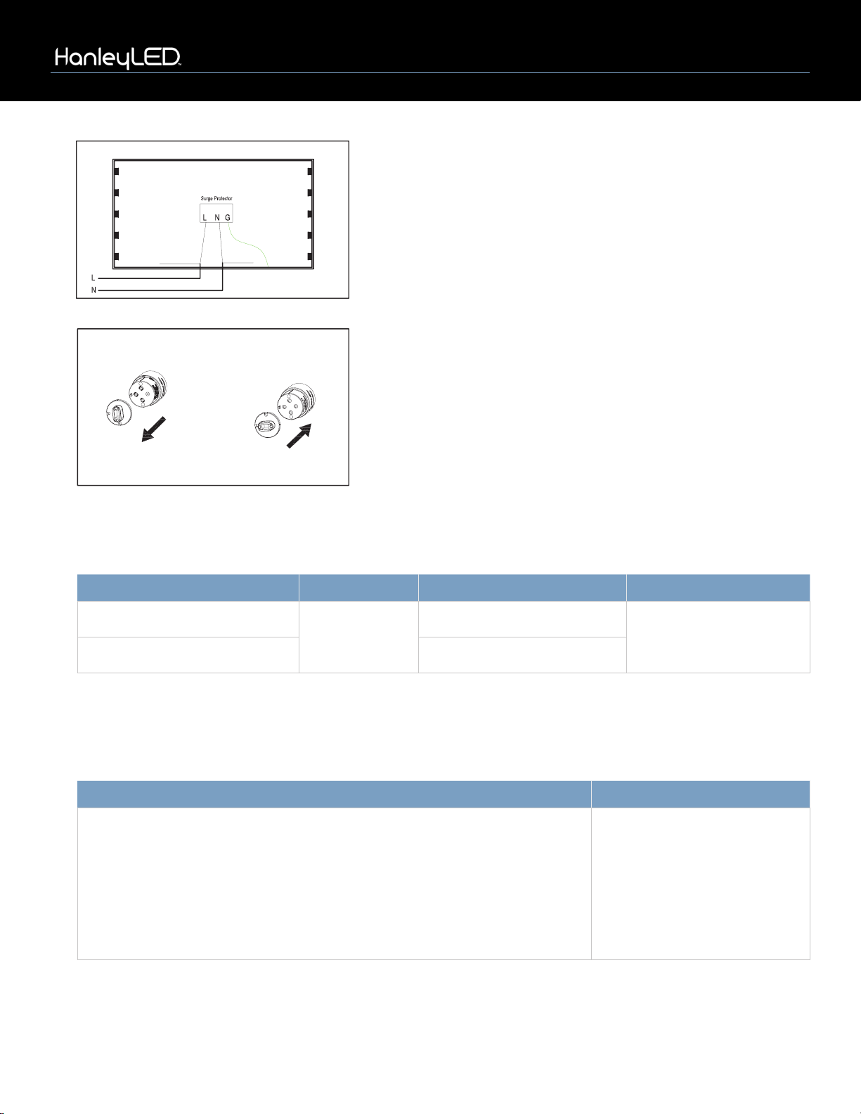
4. Connect UL approved surge protector by connecng black
wire (L) of surge protector to input (L) line from primary and white
wire (N) of surge protector to (N) neutral line from primary and
connect green wire (G) to the ground wire of cabinet.
*Only one SPD per circuit
PLG Exhibit 2053
Grimco, Inc. v. Principal Lighting Group, LLC
IPR2021-00968
Page 6
PHOENIXNRG STREAMLINER INSTALLATION GUIDE
8hanleyledsoluons.com | 800.542.9941
Vertical Horizontal
6. PhoenixNRG Streamliners should be installed with the LEDs
aimed directly at the face. If the Streamliners are oriented in the
wrong direcon inside the socket, the socket cap can be removed
and reposioned. With a pair of pliers, pull out the socket cap and
reinsert the cap in the desired posion.
*Use the double-sided Streamliners for single-sided signs and for extra deep, double-sided signs that require mulple lamp bays.
*Above warranty period is only for Streamliners used inside of water proof signs. See HanleyLED Limied Warranty Policy for more details.
5. Connect input (L) line from primary to all wires coming from
sockets on one side of cabinet and (N) neutral line from primary to
all wires coming from the sockets on the other side of the cabinet.
Install Streamliner Tubes into sockets.
LAYOUT GUIDELINES
WARRANTY
Double-sided Light Box Depth Item Average Space Between Tubes Comments
9” (4.5” single-sided)* PhoenixNRG
Streamliner by
HanleyLED
9” Light box size: 47” x 67”
Tested with 3/16”
7328 white acrylic
12” (6” single-sided)* 12”
Model No. Warranty Period
HPEB-SL2S24, HPEB-SL2S30, HPEB-SL2S36, HPEB-SL2S42, HPEB-SL2S48,
HPEB-SL2S60, HPEB-SL2S64, HPEB-SL2S72, HPEB-SL2S84, HPEB-SL2S96,
HPEB-SL2S108, HPEB-SL2S117, HPEB-SL2S120
7 year (product), 5 year (labor)
when used with HanleyLED
Surge Protector (HPEB-SP10KV)*
5 year (product), 2 year (labor)
when used without HanleyLED
Surge Protector*
PLG Exhibit 2053
Grimco, Inc. v. Principal Lighting Group, LLC
IPR2021-00968
Page 7

PHOENIXNRG STREAMLINER INSTALLATION GUIDE
9hanleyledsoluons.com | 800.542.9941
Cautions for installation and use:
• Disconnect the power before installaon to ensure safety.
• Disconnect or remove the exisng ballast before installaon to avoid short circuit.
• This product must be installed by a qualied electrician or electrical engineer.
• This product must be installed according to the requirements and instrucons in the specicaon sheet.
• A surge protector is recommended to be used with this product to prevent damage caused by power surges,
inrush current and other environmental causes of power spikes.
• This product is not intended for use with dimmers; not intended for emergency lighng.
• Suitable for dry and damp locaons; suitable for use in enclosed luminaries.
• To prevent wiring damage or abrasion, do not expose wiring to edges of sheet metal or other sharp objects.
CAUTIONS
TROUBLESHOOTING
Malfuncons Possible Causes Soluons
All LEDs do not work
No power from primary Double check primary connecons and turn power on
Poor contact between
socket and product
Remove and reinstall the product or adjust the lamp holders;
Replace damaged sockets
Driver inside the
product is damaged Replace damaged tube with new tube
Part of LEDs
do not work
No electricity to those
LEDs due to open circuit Maintain the circuit or replace with new tube
The diodes inside
the modules fail
Conrm voltage from primary is stable & safe;
replace with new tube.
Brightness of LEDs
is weak or uneven
LED diodes inside
modules malfuncon Replace with new modules or new product
Power input of
driver is insucient Replace with new product
LEDs are blinking
Driver inside the
product is damaged Replace with new product
Poor contact between
socket and product Adjust the contact between the tube and socket
WARNING – Risk of re or electric shock. LED Retrot Kit installaon requires knowledge of sign electrical systems. If not qualied, do not aempt
installaon. Contact a qualied electrician.
WARNING – Risk of re or electric shock. Install this kit only in host signs that have been idened in the installaon instrucons and where the input
rang of the retrot kit does not exceed the input rang of the sign
WARNING – Risk of re or electric shock. Installaon of this LED retrot kit may involve drilling or punching of holes into the structure of the sign.
Check for enclosed wiring and components to avoid damage to wiring and electrical parts.
WARNING – To prevent wiring damage or abrasion, do not expose wiring to edges of sheet metal or other sharp objects.
Do not make or alter any open holes in an enclosure of wiring or electrical components during kit installaon.
Only those open holes indicated in the photographs and/or drawings may be made or altered as a result of kit installaon.
Repair and seal any unused openings in the electrical enclosure. Openings greater than 12.7 mm (1/2 in.) diameter require a metal patch
secured by screws or rivets and caulked with non-hardening caulk. Smaller openings may be sealed with non-hardening caulk.
PLG Exhibit 2053
Grimco, Inc. v. Principal Lighting Group, LLC
IPR2021-00968
Page 8
Table of contents
Other HanleyLED Lighting Equipment manuals


Popular Lighting Equipment manuals by other brands


HAUL MASTER
HAUL MASTER 63115 Owner's manual & safety instructions

RAB Lighting
RAB Lighting WPLED10 installation instructions

Luminar
Luminar EVERYDAY 59250 Owner's manual & safety instructions

Volt
Volt VUL-680 Series installation instructions

luminetworx
luminetworx LVES-F2231CA Installation sheet

DreamLED
DreamLED OLS-100 user manual