TPCAST VIVE User manual

User Guide on installation of
TPCAST Wireless Adaptor for VIVE
CE-01H-UG-EN-006
新版印刷(无蓝牙)英文 2017-05-24-US.indd 1
2017/5/24 上午10:51

What's insidethe box
1
Instructions ofmain components
2
Connection instructions
3
Installation of Software Client
4
Operation instructions
5
Instructions on erection of PC transmitter
6
Safety and Note
7
Frequently asked questions
8
CONETENTS
新版印刷(无蓝牙)英文 2017-05-24-US.indd 2
2017/5/24 上午10:51

Please read the user guide prior to operating of the product.
Update the soft copy of user guide on a regular basis to improve the
accuracy and completeness.
Please visit the website of www.tpcast.cn to get the up-to-date
version.
Scan code to view installation
video of Wireless Adaptor for VIVE
Because there is no cable effect, you should pay attention to
the safety of game area during using TPCAST Wireless Adaptor
for VIVE, to ensure that will not touch to the surrounding objects,
or take the experience under the care of others.
新版印刷(无蓝牙)英文 2017-05-24-US.indd 3
2017/5/24 上午10:51

1. What's inside the box
1
9 10 11
②PC tr ansmitte r
③Pow er b ox
⑦Instructions and warranty card
④Porta ble power bank of 20000mAh
⑤De dicated cable for long distance connectio n
⑥HDMI shortconnection cabl e
⑧Nylon Bag
①HM D Recei v er
⑨Router
⑩Router power supply
1 2 3
578
4
6
elbackrowteN
11
新版印刷(无蓝牙)英文 2017-05-24-US.indd 4
2017/5/24 上午10:51

2. Instructions of main components
2
1、HMD Receiver
2、PC transmitter
①HDMI connection port
②DCIN power port
③Video link pairi n g bu tto n
④Port for fixi n g the platform
⑤Indicator for v ideo s ignalconnectio n
1 2 3 4 5
①HM D s tr a p andcable p ort
②HDMI shortconnection port
③Indicator for v ideo s ignalconnectio n
④USB port
⑤Video link pairi n g bu tto n
5
1
2
3
4
新版印刷(无蓝牙)英文 2017-05-24-US.indd 5
2017/5/24 上午10:51
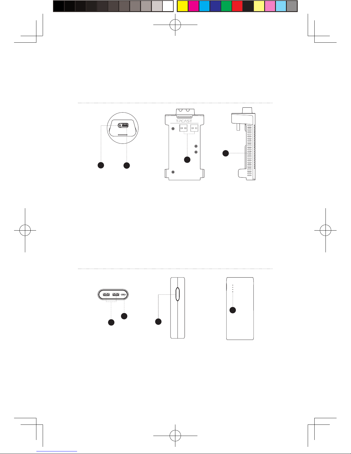
3、Po w er b ox
4、Portable power bank
①DCIN p o wer port for d e dicate d l ong dist ance connection cable
②USB port for de dicat ed l ong dis tance connection cable
③USB port for portable power bank
④Indicator for V R wireless op e ratin g s ignal
12
3
4
①USB power output port
②Mi cro USB c harging p ort
③Ba ttery i ndicator b u tton
④Ba ttery i ndicat o r
1
2
4
3
3
新版印刷(无蓝牙)英文 2017-05-24-US.indd 6
2017/5/24 上午10:51

5、Route r
①Ne twork cable port
②Router po w er ad a pter port
③St a tus ligh t for t he router
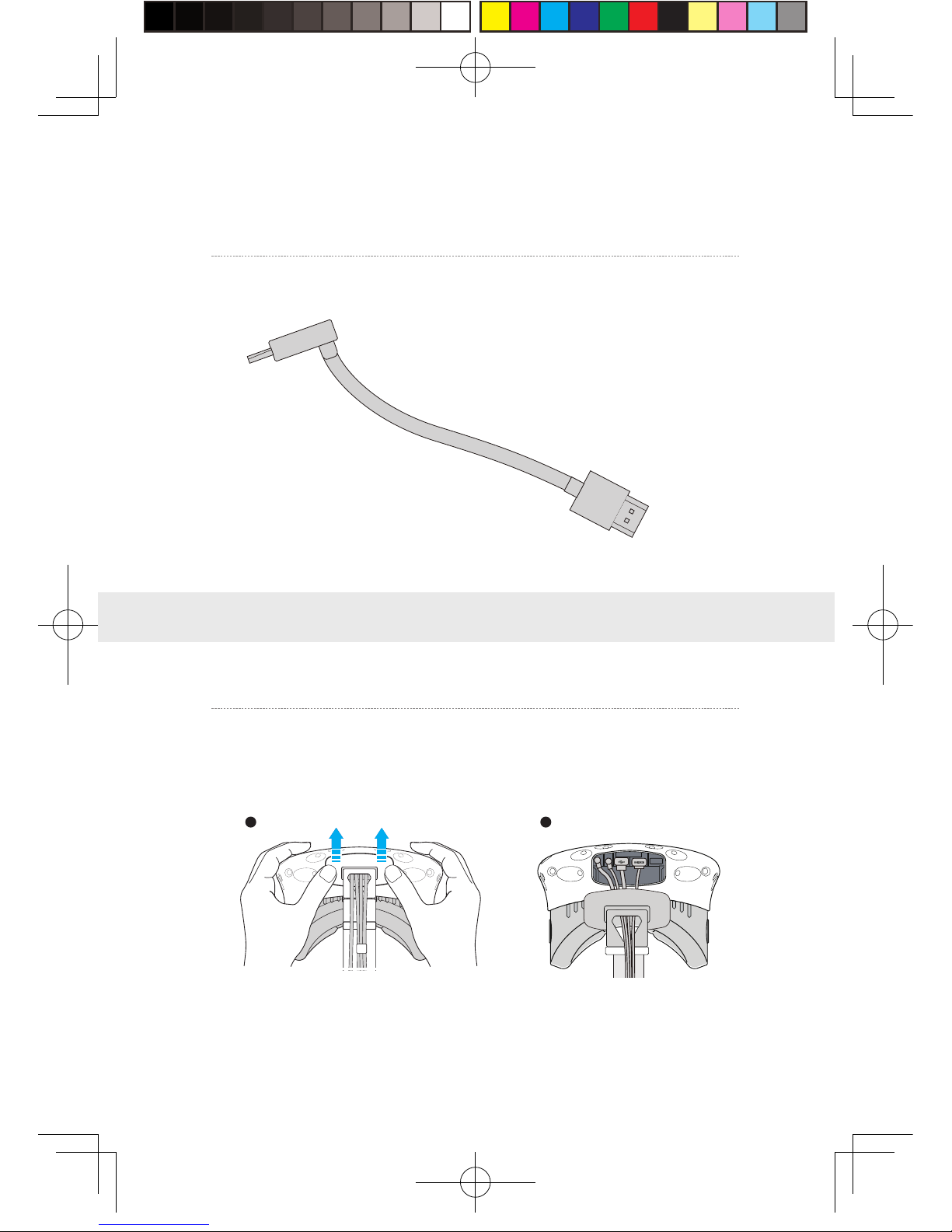
6、Ca ble
Dedicated cable for long distance connection
1-A
1- C
1- B 1 -D
1- E
USB
USB
DC
DC
4
2
3
1
新版印刷(无蓝牙)英文 2017-05-24-US.indd 7
2017/5/24 上午10:51
3. Connection instructions
HDMI cable for short distance connection
2-A
2- B
St e p one: Unplug t he connect e d c able s
①As shown in the figure, open the compartment co ve r.
1、Instructions on connection of H M D Recei v er
1 2
HDMI
HDMI
5
新版印刷(无蓝牙)英文 2017-05-24-US.indd 8
2017/5/24 上午10:51

②Unplug all power cable, 3-in-1 cable as well as the audio cable, there are four
interfaces in total.
③Pu ll t he 3-in-1 cable and audio cable out of t he compartment
and the str a p t o completely sepa ra t e from t he H M D.
④Sepa ra t e t he st ra p from t he compartment .
6
新版印刷(无蓝牙)英文 2017-05-24-US.indd 9
2017/5/24 上午10:51

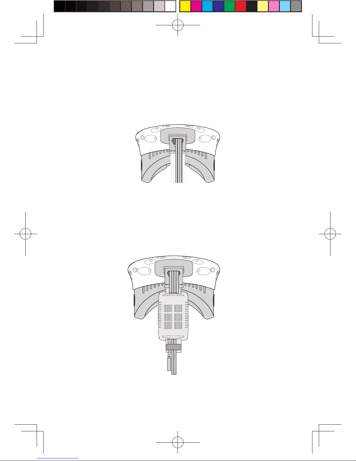
St e p two: F i x the HM D Recei v e r
①As shown i nt he figure, thread in all t hree interfaces ( 1- a, 1-b
and 1-c) of the d e dicate d l ong dist ance connection c able and
audio cable from the HMD receiv er withTPCAS T side and outof
the ot her side .
No t e: T he curve d USB plu g through the t hreadhole, need to
forcibly fi n ger a l ong the r igh t direction to pass throug h .
Step three: Cable connection
①As shown in the figure, thread in all three interfaces (1-a, 1-b and1-c)
of the dedicated long distance connection cable and audio cable from the
HMD receiver withTPCAST side andoutof the other side.
Note : The curved USB plug through the thread hole, need to forcibly
finger along the right direction to pass through.
②Thread t he sep ar ate d s t r a p t hrough the H MD cable ports i n
turn and route d under the d edicat e d longconnection cable, then
the rece i ver end will be fixe d on the H MD s t ra p .
7
新版印刷(无蓝牙)英文 2017-05-24-US.indd 10
2017/5/24 上午10:51

②Rec onnect s t ra p to the compartmentc ov e r.
③Thread t he 1 -a and1 -b in t erfaces of long connection cable
through t he compartmentc ov er cablep ort, a n d t he 2 -a interfac e
of shortconnection cable as we ll.
④In turn plug i n these t hree in t erfaces i n t o the VIVE H M D p o w er
port, USB p ort , HDMI port andaudio connector port .
8
新版印刷(无蓝牙)英文 2017-05-24-US.indd 11
2017/5/24 上午10:51
⑤St ra igh t en out the cable, hatch co v er back ag a i n, it is
recommende d that you a djust t he length of t he s lidin g z one t o
meet the H M D receiv er to the end of s lidin g zone and t he cable
still tight .
St e p four: O ve ra ll a djustment
①Slidet he interface of l ong connection cable(to b e plugged in t o
the po w er supply) through these two sleev es at the back of H M D
andhangon the back.
新版印刷(无蓝牙)英文 2017-05-24-US.indd 12
2017/5/24 上午10:51

St e p one: As shown in the figure, respective l y connect t he d and
e interfaces of long connection cablet o the p o w er b ox and HDMI
port;
St e p two: A s show n int he figure, connect the port ablep o wer
bank tot he powerb ox a nd whe n successf u lly connected,t he blue
ba ttery ligh t on the port a ble power bank turns on to i n dicate
the st a te of charge. In order t o i mp r ov e the utilization r at e of
ba ttery charge, please onl y connect to the port a ble power bank
prior to ope ra tion o f t he p roduct . Anda fter o pe ra tion, remov e
the port a ble power bank in the fi rst place.
St e p three: P u t the comple t e d p o w er supply as w ell as the power
bo x in a porta ble pack and s tr i ng t he pack t o preventfalling o f
power supply in motion.
2、Power box connection instructions
1 2 3
10
St e p one: Disconnect pow er s upply for VIVEstreami n g b o x .
St e p two: As for the exi s ting VIVE3 -in -1 cabled e tached f rom
the HM D, connect the DCIN po wer i n t erface and the HDMI
interface to t he correspondin g port on the PC t ransmitte r, and
3、Instructions on connection of PC transmitter
新版印刷(无蓝牙)英文 2017-05-24-US.indd 13
2017/5/24 上午10:51

4、Instructions on connection of router
St e p one: Connect the router power ada pter andconfirm power
in dicator on t he frontof panel is on.
St e p two: Connect the y e llow portof router to the PC host
through network c able, as shown in the figure.
St e p three: In PC’s network connection Settings o f W in d ow s
system, select“Localconnection” to connect t he router o f
wireless adaptor, change the connection of TCP/IP Settings t o
automatically obtai n I P address and DNS server address.
No t e: DO N OT make any settings in the rout e r. DO NOT restore
factory se ttin gs. Please use it directlyw hen connectin g
network ca ble. In order to optim iz e user's p roductexperience,
we recommend t o place the router i n an o p en location with a
90-degree antenna, there is no obvious ob s tacles b e tween the
router and VIVE product.
In order to ensure PC can access to the Internet normally while wireless adaptor
is in usage, it need to insert the original network cable to WAN port of the
router.
11
the USB in t erface is not required to b e connect ed .
St e p three: Connect power supply for VIVE streaming box.
LAN Port
WAN Port
新版印刷(无蓝牙)英文 2017-05-24-US.indd 14
2017/5/24 上午10:51

1、Download the soft w are client
4. Installation of software client
TPCAST Wireless Adaptor for VIV E
12
Visit the w e bs ite of TPCA S T wh i ch i s www. tpcast.cn and l o g i n,
browse the pa g e of TPCAS T wireless a d a ptor for VIVE, click t o
download the wireless a d a ptor for VIVEassis t ant. T he current
version of client is compatible withWindo w s 7, Windows 8 or later
version, Win d ow s 10.
①Double click the icon to run t he download ed .exe file for
in stallation. Ifa lready insta lled a ny o ther versions o f t he client ,
please uninsta ll a nd restart t he PC a ccording t o the prompt.
2、Install the connection assis t antsoft ware
②Following the instructions o f t he system, select the inst a llation
path, complete the client i nst allation, a n d gener a t e deskt o p
shortcut icon of wireless ad a ptor connection assis t ant.
TPCAST
Setup.exe
新版印刷(无蓝牙)英文 2017-05-24-US.indd 15
2017/5/24 上午10:51

1、Installation verif y
2、Pa i r H M D recei ver withPC t rans m itte r
Verif y a ll connectionsof the wireless adaptor incl u ding the H M D
Rec e iv er, PC tr ansmitte r, po w er b o x & port a ble power bank,
route r, andmake sure the port able power bank i s fully charg e d .
5. Operation instructions
Pai r H MD rec e i v er withPC tr ansmitter for the f i rst time ope ra tion
only.
①When the po w er is on, the video s ignalconnection i ndica t ors
on bo t h rece i ver end and t ransmitter will s tart blinki n g s l o wly.
②Then keep p ushin g the p ai r in g b utton on both ends for at l east
5 seconds till all i n dicators are off.
③Ensure there is no ob s tacles b etween the t r ansmitter and
rece i ver endand release the p ai r in g b uttons. The video signal
in dicator will return t o sl o w blinking mode after about5 second s .
④No more op e ra tion and w ait f or about 10 seconds till the signal
in dicator change t o fast blinking mode which means the pa i ri n g
is complet e d. In the second operation, the signal in dicator will
quickly blink about10 seconds after the energization.
13
新版印刷(无蓝牙)英文 2017-05-24-US.indd 16
2017/5/24 上午10:51

3、Erect PC tr ansmitter
Appropriately erect b ased on the currents ite condition for
optimaloutcome, refer to the instructions on PC trans m itter
setu p for d etails.
14
4、Run wireless ada ptor connection assistant
Double-click the PC deskto p c lient icon, then click “Start ” after
the clients tart ed .It will automaticallyt est t he e nv i ronment
of wireless adaptor workin g int urn .When wireless connection
starts, please startVIVEPort and S t eamVR software.
5、En j o y wireless V R
In normalop e ra tion of wireless a d a pto r, the indicators of b o t h
tr ansmitter a n d receiv er end will chang e from fast blinki n g to
normal light mode, H M D imagin g function andm anualop e ration
shall be normal .
Erection of PC tr ansmitter is subject t o t he specific s ituation of
proposed location, the set u p plan, therefore dif f erent setu p plan
will be applie d accordingly t o differentcases. We recommend to
setu p t he PC tr ansmitter w here close to your VIVE laser locator
(light house) and turn the sidewith t ag s a gainst the play area.
As shown be l ow :
6. Instructions on setup of PC transmitter
新版印刷(无蓝牙)英文 2017-05-24-US.indd 17
2017/5/24 上午10:51
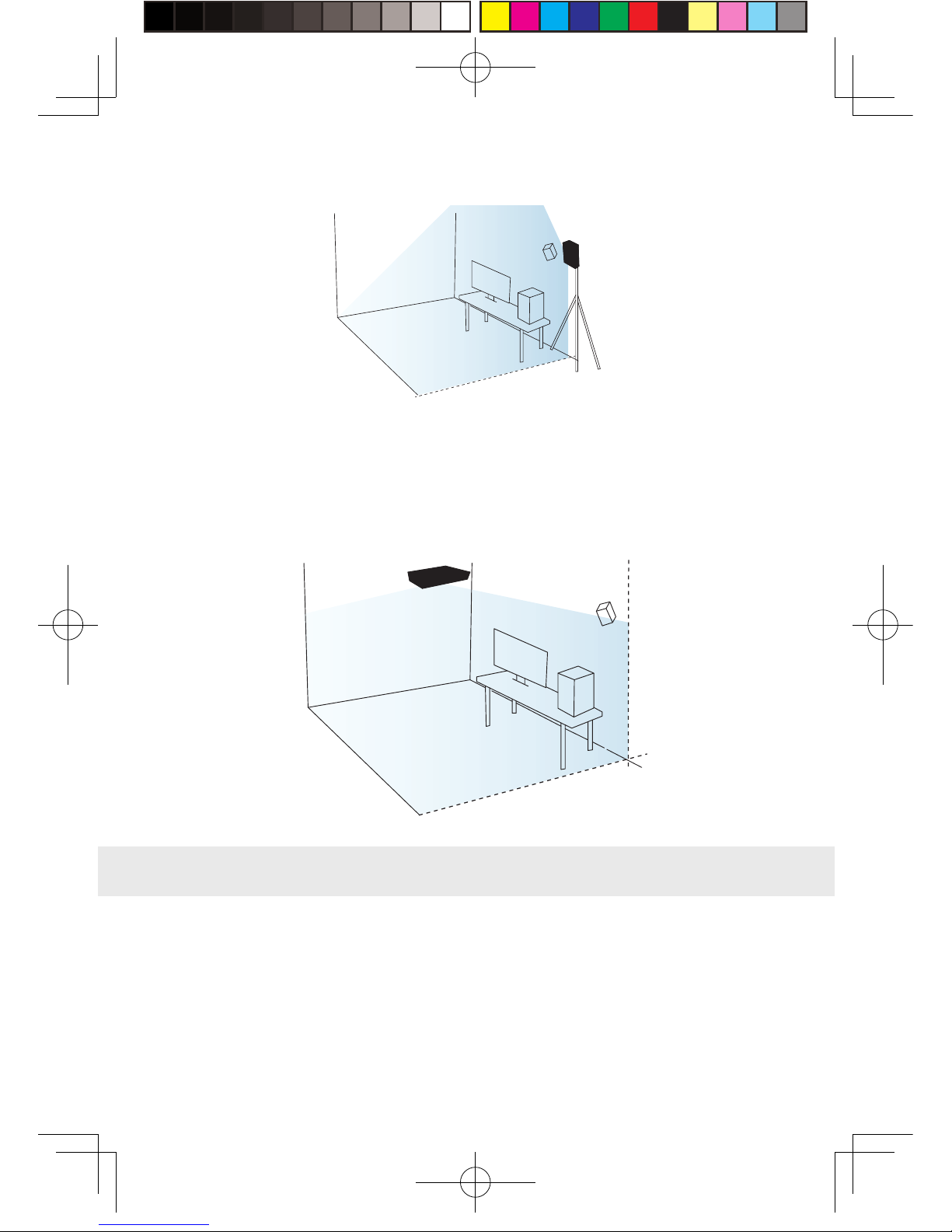
PC transmitter
If failure of connection still occurred, followin g t he instructions
from abo ve, or you are experienci n g s l u ggish video pla y or
stopping in some angle, corner, we will suggest you placin g the
tr ansmitter abo ve the play area, as shown b e lo w :
Safety :
User need to pa y attention t o safet y with in the pla y area since i t ’s
free of tangling b y cable s or wires. T he user shall not b ump in t o
an y t h in g around t he play area or the play is under wa t ch.
7. Safety and note
PC transmitter
15
新版印刷(无蓝牙)英文 2017-05-24-US.indd 18
2017/5/24 上午10:51

16
Ca ble :
In order to cont a in t he damage may cause t o t he cable s , i t ’ s
suggeste d not p ulling cable t o fetch t he ada ptor or unplu g an y
plug s or interfaces.
Heatrejection:
The ada ptor will g enera t e heat duri ng normalo p er a tion and
the temp e r a t ure on t he surface may rise up a fter l ong perio d
operation. Please immediat e l y s t o p operation andcontact our
customer service when abnormal heat generation occurred .
Ba ttery saf e t y :
The porta blep ow er b ank as incl u d e d i n the a daptor p ackage is
power supply de dicat e d for t h is p rod uct, you must notrepla c e with
an y non-TPCAS T port able power bank, anda ny damag e caus e d
accordingly will wa iv e the wa r r anty o f t he a d a pto r. In order to
mitigat e t he ri sk of fire hazardor combustion hazard, please d o
not disassemble, squeeze t he port a ble power bank and shall not
expose the po w er su pply to env i ronmentexceeding 6 0 ℃, or toss
into the fi re or w a t e r.
Ch ildren use:
Ch ildren are nota llo w e d t o use t h is product, please k eep t h is
product in appropriate locations w here b ey ondreach o f c h ildren
and please not grantaccess to children. Ife lder children are
allow e d to use this product, ple a se do proceedunder clos e w a tch
of adu lts .
Rec harging:
The porta blep ow er b ank can be recharg e d t hrough the household
cell phone charged and char ger greatert h a n 2A is recommended in
order to reduce the chargin g p eri o d . Nine t o twe l v e hours will b e
neede d t o be fully charge d . Charger greater than 2.4A shall not b e
used for recharging.
新版印刷(无蓝牙)英文 2017-05-24-US.indd 19
2017/5/24 上午10:51

Wh y alw ays f a ile d t he V R controlconnection test s ?
①Check the testres u lts andcheck the po w e r, router whether is
properly insta lle d followin g t he instructions, andenergiz e .
②If still failed the tests after sev er a l t r y, re-inst a ll the port a ble
power bank, router and the reboot the computer i f necessary.
③Rel aunch the wireless ad a ptor connection assi s t ant a n d ret r y,
please contact the customer service if t he problem i s still not
solv e d .
Ho w to veri fy t he p a i r i n g of recei v er end and t r ansmitter?
①Make sure the recei ver and t ransmitter are connect e d and
energize d , and there i s no o bs t acles in be tween, i n compliance
with setu p req ui rement s .
②Pai r followin g the op e ra tion instructions, i f t he in dicators
switch from slo w blinking mode t o fast blinking mode for
ab out15 seconds after energiz e d , then the pair is successfully
1、Connection issues
8. Frequently Asked Questions
17
Service andmain t enance
The ada ptor is non-wa terproof p roduct, therefore a ttention shall
be a ttached f or proper protection i ncl u din g shall notuse blo we r,
ai r d uct, etc. to d ry t he product when w e t or t he product m a y
ot herwise not b e able t o normally op e r a tin g .
Plea se d o not disassembleth i s product and av o id a ny surprised
collisi on, otherwise, r isk of e l ectric shock, shortc i r c u it andf ire
hazard would be i nv o l v e d .
Plea se o pe ra t e and maintain in an environmentof t emp e ra t ure
ranging from zero to forty degrees C e ls i us.
Plea se u se t he parts permitte d only an d shall notconnect t o an y
incompa tible product s or part s .
Please refer the local regulations on di spo sal of electronic w aste s
for proper w aste ma n agement.
Plea se d o not spread the small s i z e objects the into the p roducts
through t he surface vent s .
Plea se d o not clean this product with any irritating chemical ,
detergent, liquid d e tergentor aerosol .
新版印刷(无蓝牙)英文 2017-05-24-US.indd 20
2017/5/24 上午10:51
Other manuals for VIVE
2
Table of contents
Other TPCAST Adapter manuals


