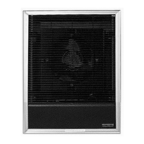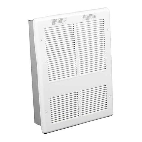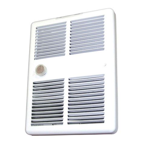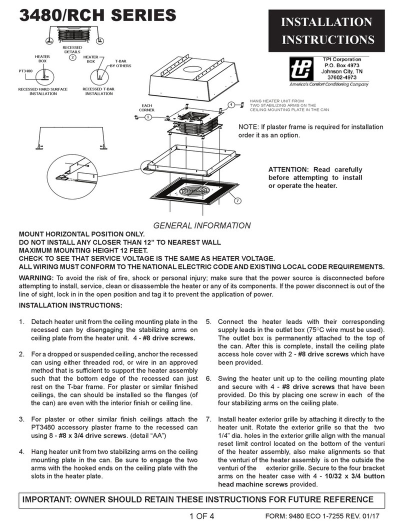
FIG.1FLUSHMOUNT
FIG.2SURFACEMOUNT
141/4
(362mm)
193/16
(490.5mm)
8”(203.2)Minimum
ToFinishedFloor
8”(203.2)Minimum
ToFinishedFloor
SERVICECABLE
OR CONDUIT
Wall Installation
7.CLEANING ANDMAINTENANCE INSTRUCTIONS:
A. At the beginningof eachheating season, disconnect electrical
power atcircuit breakerpanel. Remove front grille.
B. Use the narrow (crevice” suction attachment of the vacuum
cleaner to remove dust andlint from heater and heating element.
C.Lubricatethe motorwith SAENo. 10oil.Two(2)oilspoutsare
locatedon frontand backof motor.
D.Reinstall front grille with previously removed screws. Restore
power tothe heater.
Note:This heater employs a visual alarm (light)towarn that partsof the
heater are gettingexcessively hot. If thealarm illuminates, immediately
disconnect powerfrom heater and inspectfor any objects onor adjacent
to theheater that may causehightemperatures. DONOTOPERATE
HEATERWITHTHEALARM(LIGHT)ILLUMINATED.
FPQ
3310 SERIES
IMPORTANT:OWNERSHOULDRETAINTHESEINSTRUCTIONSFORFUTUREREFERENCE
INSTALLATION
INSTRUCTIONS
Form 9821
ECO 15340
1.LOCATIONOFHEATER:
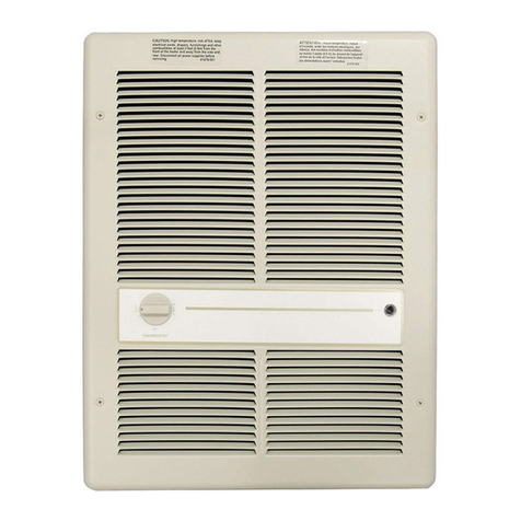
A. Heateris mountedonthe wallnear ceiling or floor,airflowdown.
CAUTION:Donotobstructthe frontgrilleoftheheaterwith
curtains, furniture,etc., since the properoperation of the heater
requires a free flowintake andexhaust of air.
B. Minimum mounting height is 8” abovefinished floor.
C.For surfacemounting useadapter FQP/3310EX33.
2.BEFORE MOUNTING:
A. Insure thatthe supply voltage matches voltage ratingon the label of
the heater.
B. Turnoff electrical power to heater circuit.
4.WIRINGINSTRUCTIONS REF:Diagrams WD1, WD2, WD3, WD4.
A.FieldConversionforLowerWattage:Allunitsarefactorywired
forhigherwattage rating.(Seeparagraph9forconversion tolower
wattagerating).
B. Bringservice leads throughknockout “K” on top or bottom of rough
in boxfor flushor semirecessed mounting, bottomknockout “K”
only for surfacemounting. When wiring from the bottom, installwire
throughcover “G”by removingscrew“H”.
C.Attach serviceleads totwo black leads on208240 volt models and
to blackand white leads on120277 voltmodels, attach ground lead
to green wire with approved connectors.Comply with all national
and local codes.
D.Attach wiring compartment cover “D” to assembly with screw “C”.
3.MOUNTING INSTRUCTIONS:
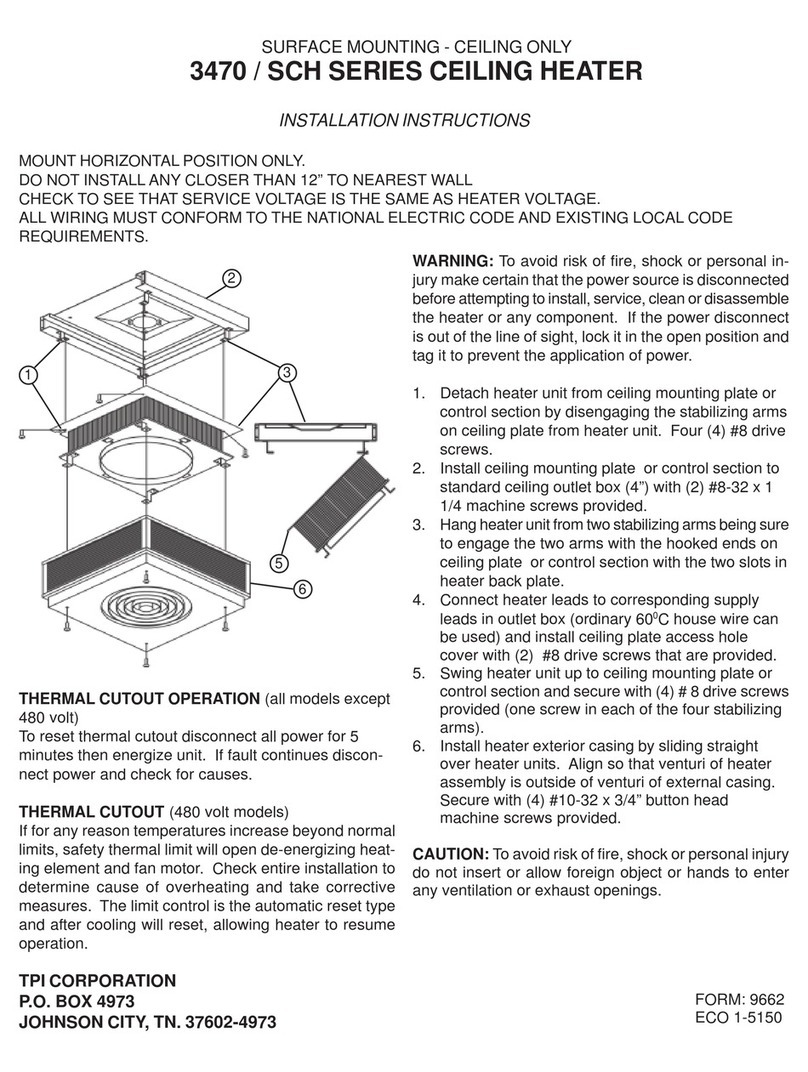
A. Disassemble heaterby removing7 screws “C”as showninFigure
1and2.
B. Flush mounting, see Fig. 1.
Placeroughin box “A” betweenstuds at desired height: secureto
studs throughholes “M”.Theflangesonthe roughinboxmustrest
onthesurfaceofthe finishedwall;if theboxisinstalledpriortothe
application of the finished wall, allowancemust be made for the wall
thickness.
C.Surface mounting, See Fig. 2.
Insert roughin box “A” into surface adapter “E”. Secure theheater
roughin box to wallatdesired heightthroughholes“X”.Besure
thattheroughinbox is centeredinsurfaceadapter.For surface
mounting, bring wiring throughbottom knockout “K” only.
D.Place assembly“B” into roughin box“A”. Secure with sixscrews“C”.
5.FINALSTEPS:
A. Clean all construction dirt anddebris from inside heater.
B. Attachfrontgrille“F”withfourscrews“L”.Aparts bagcontaining
the coverscrews and the thermostat knob is located inside of heater.
C.Attach thermostatknob “T”.
6. OPERATING INSTRUCTIONS:
A. Turnonpower at the circuitbreakerpanel.
B. If therearetwo controls on thefrontgrilleoftheheater;theone on
your left“T” isthethermostat controlandshouldbesettothe
positiontogive the desired comfortheat intheroom.The switch on
your right isthe modeselection switch. Two modes of heating
operation are available: CONSTANT:Fan runscontinuously while
thermostat cyclesheating elements on andoff as required by
setting;andAUTO: Fan andheatingelements cycle on andoff
simultaneously on thermostatcontrol. Thefan can be operated
separately to circulate room temperature air by turning thermostat to
itslowestsetting andplacing fanselectorswitch inthe “CONSTANT”
position.
C.Afterthe desired temperature isreached, turnthermostat stem
counter clockwise until a click is heard fromthe thermostat.
D. Models with double pole thermostats: Turn thermostat adjustment
knobfullycounterclockwisetothe“OFF”position.Thiswill
deenergize theheatingelementandfan.
