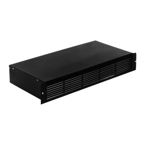
TPI FPQ 3310 Series User manual

1
1. LOCATION OF HEATER:
A. Heater is mounted on the wall near ceiling or oor, air ow down.
CAUTION: Do not obstruct the front grille of the heater with curtains,
furniture, etc., since the proper operation of the heater requires a free
ow intake and exhaust of air.
B. Minimum mounting height is 10” above nished oor.
C. For surface mounting use adapter FPQ/3310EX33.
2. BEFORE MOUNTING:
A. Insure that the supply voltage matches voltage rating on the label of the
heater.
B. Turn off electrical power to heater circuit.
3. MOUNTING INSTRUCTIONS:
A.
Disassemble heater by removing 7 screws “C” as shown in Figure 1 and 2
.
B. Flush mounting, see Fig. 1.
Place rough-in box “A” between studs at desired height: secure to studs
through holes “M”. The anges on the rough-in box must rest on the
surface of the nished wall; if the box is installed prior to the application
of the nished wall, allowance must be made for the wall thickness.
C. Surface mounting, See Fig. 2.
Insert rough-in box “A” into surface adapter “E”.
Secure the heater rough-in box to wall at desired height through holes
“X”. Be sure that the rough in box is
centered in surface adapter. For surface mounting, bring wiring through
bottom knockout “K” only.
D. Place assembly “B” into rough-in box “A”. Secure with six screws “C”.
4. WIRING INSTRUCTIONS REF: Diagrams WD1, WD2, WD3, WD4.
A. Field Conversion for Lower Wattage: All units are factory wired for higher
wattage rating. (See paragraph 9 for conversion to lower wattage rating).
B. Bring service leads through knockout “K” on top or bottom of rough-in
box for ush or semi-recessed mounting, bottom knockout “K” only for
surface mounting. When wiring from the bottom, install wire through
cover “G” by removing screw “H”.
C. Attach service leads to two black leads on 208-240 volt models and to
black and white leads on 120-277 volt models, attach ground lead to
green wire with approved connectors. Comply with all national and local
codes.
D. Attach wiring compartment cover “D” to assembly with screw “C”.
5. FINAL STEPS:
A. Clean all construction dirt and debris from inside heater.
B. Attach front grille “F” with four screws “L”. A parts bag containing the
cover screws and the thermostat knob is located inside of heater.
C. Attach thermostat knob “T”.
6. OPERATING INSTRUCTIONS:
A. Turn on power at the circuit breaker panel.
B. If there are two controls on the front grille of the heater; the one on
your left “T” is the thermostat control and should be set to the
position to give the desired comfort heat in the room. The switch on
your right is the mode selection switch. Two modes of heating
operation are available: CONSTANT: Fan runs continuously while
thermostat cycles heating elements on and off as required by
setting; and AUTO: Fan and heating elements cycle on and off
simultaneously on thermostat control. The fan can be operated
separately to circulate room temperature air by turning thermostat to its
lowest setting and placing fan selector switch in the “CONSTANT”
position.
C. After the desired temperature is reached, turn thermostat stem counter
clockwise until a click is heard from the thermostat.
D. Models with double pole thermostats: Turn thermostat adjustment
knob fully counter-clockwise to the “OFF” position . This will d-energize
the heating element and fan.
FPQ
3310 SERIES INSTALLATION
INSTRUCTIONS
FIG. 1 FLUSH MOUNT
FIG. 2 SURFACE MOUNT
IMPORTANT: OWNER SHOULD RETAIN THESE INSTRUCTIONS FOR FUTURE REFERENCE
X
F
Y
L
10" OR (254)mm
MINIMUM TO
FINISHED FLOOR
E
SERVICE CABLE
OR CONDUIT
K
G
H
C
D
P
Q
10" OR (254)mm
0"
0"0"
Form 9821 ECO 1-7472 REV. 10-19-18
19 1/2
(490.5 mm)
14 1/8
(362 mm)
10" OR (254)mm
MINIMUM TO
FINISHED FLOOR
A
PLFC
D
Y
H
GK
Q

2
IMPORTANT INSTRUCTIONS
1. When using electrical appliances, basic precautions should always be followed to reduce the risk of re, electrical
shock, and injury to persons, including the following:
2. Read all instructions before using this heater.
3. CAUTION: High temperatures. Keep cords and all other combustible material, such as furniture, papers, clothes
and curtains away from the heater. For safe and efcient operation, keep an open space around heater of three feet in
front and 12 inches at ends and rear.
4. Extreme caution is necessary when any heater is used by or near children or invalids and whenever the heater is left
operating and unattended.
5. Do not operate any heater after it malfunctions, has been dropped or damaged in any manner. Return heater to
authorized service facility for examination, electrical or mechanical adjustment, or repair.
6. Do not use outdoors.
7. To disconnect heater, turn controls to off, and turn off power to heater circuit at main disconnect panel (or operate
internal disconnect switch if provided).
8. Do not insert or allow foreign objects to enter any ventilation or exhaust opening as this may cause an electric chock or
re, or damage the heater.
9. To prevent a possible re, do not block air intakes or exhaust in any manner.
10. A heater has hot and arcing or sparking parts inside. WARNING: Do not use it in area where gasoline, paint, or
ammable liquids are used or stored.
11. Use this heater only as described in this manual. Any other use not recommended by the manufacturer may cause re,
electric shock, or injury to persons.
12. This heater may include an audible or visual alarm to warn that parts of the heater are getting excessively, hot. If the
alarm sounds (or illuminates), immediately turn the heater off and inspect for any objects on or adjacent to the heater
that may have blocked the airow or otherwise caused high temperatures to have occurred. DO NOT OPERATE THE
HEATER WITH THE ALARM SOUNDING (OR ILLUMINATING).
13. SAVE THESE INSTRUCTIONS
SWITCH LOCKOUT
For switch lockout hasp
or padlock thru bracket
as shown. Note: Front
grille must remain off
during lockout.
Form 9821 ECO 1-7472 REV. 10-19-18

3
3310 SERIES
TROUBLE SHOOTING
Symptom Possible Fault(s) Remedy
Heater Does Not Operate 1. Electrical Circuit Open 1. A. Close electric circuit.
B. Verify correct supply Voltage
C. Adjust thermostat to higher setting.
2. Defective Thermostat 2. Check continuity with an ohm meter.
Replace defective part if necessary.
3. Thermal Cut Out Open
(Alarm Light On)
3. A. Remove any obstruction from front of heater.
B. Verify correct supply voltage.
Heater On But Fan Does Not Operate 1. Fan Motor Failure 1. A. Verify correct supply voltage.
B. Check motor wiring connections.
C. Replace defective motor if necessary.
9. Field Conversion For Lower Wattage:
To convert heater to a lower wattage rating.
Remove (Red Jumper) from heating element
(See WD1, WD2, WD3 and WD4). The wattage will
be reduced to half of the nameplate wattage. (See
Figure 3 for model numbers rated dual wattage)
MODEL NO. VOLTAGE WATTAGE AMPERAGE
E3313RP 120 1500 12.5
120 750 6.25
HF3315RP 240/208 3000/2250 12.5/10.8
240/208 1500/1125 6.25/5.4
HF3316RP 240/208 4000/3000 16.7/14.4
240/208 2000/1500 8.3/7.2
FIGURE 3
WD-1 3310 with Summer Fan Switch, Double Pole T-Stat and (Optional Disconnect Switch)
WD-2 3310 with Summer Fan Switch, Single Pole T-Stat and (Optional Disconnect Switch)
WD-3 3310 with (Optional Double Pole T-Stat and Disconnect Switch)
WD-4 3310 with Single Pole T-Stat and (Optional Disconnect Switch)
AIL Alarm Indicator Lights
IMPORTANT: OWNER SHOULD RETAIN THESE INSTRUCTIONS FOR FUTURE REFERENCE
120-277V WHITE
208-240V BLACK
LINE
BLACK
GND
WD-1
MOTOR
ELEMENT
AIL
THERMOSTAT
THERMOSTAT
MOTOR
THERMAL
PROTECTOR
ELEMENT
AIL
THERMOSTAT
120-277V WHITE
208-240V BLACK
GND
LINE
BLACK
ELEMENT
AIL
OPTIONAL
RED JUMPER RED JUMPER
RED JUMPER
RED JUMPER
120-277V WHITE
208-240V BLACK
LINE
BLACK
GND
MOTOR
THERMAL
PROTECTOR
ELEMENT
AIL
120-277V WHITE
208-240V BLACK
LINE
BLACK
GND
DISCONNECT
OPTIONAL
DISCONNECT
OPTIONAL
THERMOSTAT
DISCONNECT
OPTIONAL
DISCONNECT
OPTIONAL
WD-2
WD-3 WD-4
MOTOR
THERMAL
PROTECTOR
THERMAL
PROTECTOR
Form 9821 ECO 1-7472 REV. 10-19-18

4
SÉRIE 3310
DÉPANNAGE
Symptôme
L’unité de chauffage ne fonctionne pas
Problème possible
1. Circuit électrique ouvert
Solution
1. A. Fermer le circuit électrique.
B. Vériez que la tension d’alimentation
est exacte.
C. Réglez le thermostat à une valeur plus
élevée.
2. Thermostat défectueux 2. Vériez la continuité avec un ohmmètre.
Remplacez la pièce défectueuse si
nécessaire.
3. Coupe-circuit thermique
ouvert (Voyant d’alerte
allumé)
3. A. Enlevez les obstructions devant l’unité
dehauffage
B. Vériez que la tension d’alimentation est
exacte.
L’élément chauffant fonctionne,
ventilateur d’alimentation est exacte.
1. Moteur du ventilateur
défectueux
1. A. Vériez que la tension mais pas le.
B. Vériez les connexions du moteur.
C. Remplacez le moteur si nécessaire.
9. Conversion àune puissance inférieure :
pour convertir l’unité de chauffage à une
puissance nominale inférieure. Retirer le câble
de raccordement rouge de l’élément chauffant
(voir WD1, WD2, WD3 et WD4). La puissance
sera réduite à la moitié de la valeur indiquée
sur la plaque signalétique (la gure 3 indique les
numéros de modèle et les puissances nominales).
N° DE MODÈLE TENSION PUISSANCE AMPÉRAGE
E3313RP 120 1500 12.5
120 750 6.25
HF3316RP 240/208 3000/2250 12.5/10.8
240/208 1500/1125 6.25/5.4
HF3316RP 240/208 4000/3000 16.7/14.4
240/208 2000/1500 8.3/7.2
FIGURE 3
WD-1 3310 avec commutateur pour ventilateur d’été, thermostat bipolaire et (interrupteur optionnel)
WD-2 3310 avec commutateur pour ventilateur d’été, thermostat unipolaire et (interrupteur optionnel)
WD-3 3310 avec thermostat bipolaire et interrupteur optionnels
WD-4 3310 avec thermostat unipolaire et (interrupteur optionnel)
AIL Voyants d’alerte
IMPORTANT :CONSERVEZ CES INSTRUCTIONS COMME RÉFÉRENCE FUTURE
Formulaire 9821 ECO 1-7472 REV. 10-19-18
WD-2
WD-3 WD-4
CÂBLE DE RACCORDEMENT ROUGE
ÉLÉMENT
MOTEUR
INTERRUPTEUR
THERMIQUE
VOYANT D'ALERTE
THERMOSTAT
OPTIONNEL
INTERRUPTEUR
OPTIONNEL
LIGNE
NOIR
120-277 BLANC
208-240V NOIR
TERRE
CÂBLE DE RACCORDEMENT ROUGE
ÉLÉMENT
INTERRUPTEUR
THERMIQUE
VOYANT D'ALERTE
THERMOSTAT
OPTIONNEL
INTERRUPTEUR
OPTIONNEL
LIGNE
NOIR
120-277 BLANC
208-240V NOIR
TERRE
MOTEUR
CÂBLE DE RACCORDEMENT ROUGE
ÉLÉMENT
MOTEUR
INTERRUPTEUR
THERMIQUE
VOYANT D'ALERTE
INTERRUPTEUR
OPTIONNEL
LIGNE
NOIR
120-277 BLANC
208-240V NOIR
TERRE
WD-4
CÂBLE DE RACCORDEMENT ROUGE
ÉLÉMENT
INTERRUPTEUR
THERMIQUE
VOYANT D'ALERTE
INTERRUPTEUR
OPTIONNEL
LIGNE
NOIR
120-277 BLANC
208-240V NOIR
TERRE
MOTEUR
This manual suits for next models
3
Other TPI Heater manuals
TPI
TPI CV Series User manual
TPI
TPI CEH / 3380 SERIES User manual
TPI
TPI TSH5X User manual
TPI
TPI 2600 Series User manual
TPI
TPI Fostoria FHK Series User manual
TPI
TPI E3313RP User manual
TPI
TPI 3420 Series User manual
TPI
TPI 3470/SCH Series User manual
TPI
TPI 680 Series User manual

TPI
TPI CV Series User manual
TPI
TPI 6300/T Series User manual
TPI
TPI CF35-C User manual
TPI
TPI 3200 Series User manual
TPI
TPI HF5848TC User manual
TPI
TPI 2900/D SERIES User manual
TPI
TPI 3480/RCH Series User manual

TPI
TPI CEH / 3380 SERIES User manual
TPI
TPI 680 Series User manual
TPI
TPI TSH20J User manual

TPI
TPI 6300/T Series User manual
