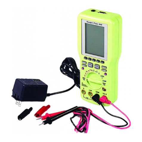
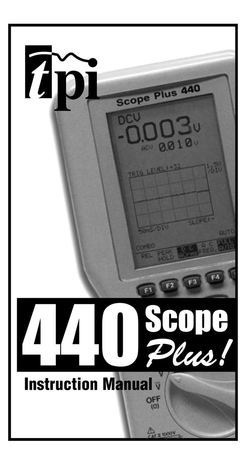
TPI Scope Plus 460 User manual

460 Handheld 20MHz
Digital Oscilloscope
User’s Guide
Test Products International, Inc.
9615 SW Allen Blvd.
Portland, OR 97005
P : 503-520-9197 !Fax: 503-520-1225
E-mail: info@tpi-t evalueleader.com
The Value Leader
www.tpi-thevalueleader.com
TM

Copyrig t ©2001
Test Products International, Inc.
All Rig ts Reserved
08/01
460 User’s Guide
ii

Table of Contents
C1 - Introduction........................................................................................C1-1
Features ..........................................................................................C1-2
Specifications ..................................................................................C1-3
Scope Modes ........................................................................C1-3
Multimeter Modes ................................................................C1-5
C2 - Getting Started ..................................................................................C2-1
Equipment Needed ..........................................................................C2-1
460 Setup ........................................................................................C2-1
Measuring Voltage ..........................................................................C2-3
Measuring Frequency ......................................................................C2-3
Measuring Resistance......................................................................C2-4
Testing Continuity ............................................................................C2-4
Diode Test........................................................................................C2-4
C3 - Operation............................................................................................C3-1
Principal Connectors and Keys ........................................................C3-1
Key / Screen Menus ........................................................................C3-3
C4 - Advanced Functions ..........................................................................C4-1
Triggering ........................................................................................C4-1
Trend Mode......................................................................................C4-1
Glitc Capture ..................................................................................C4-2
Saving Screens ................................................................................C4-2
Using t e 10:1 Probe ......................................................................C4-3
10:1 Probe Compensation Adjustment ............................................C4-3
C5 - Using Adapters ..................................................................................C5-1
Temperature Adapter - A301............................................................C5-1
Hig Current Adapter - A251 / A256 / A296 ....................................C5-1
Low Current Adapter - A254............................................................C5-2
460 User’s Guide
iii

Current S unt Adapter - A130 ........................................................C5-2
Pressure Adapter - A620 ................................................................C5-2
PC Software & RS232 Cable - A404................................................C5-3
C6 - Safety Considerations ........................................................................C6-1
Instrument ......................................................................................C6-1
Environmental..................................................................................C6-2
Appendix A - Test and Calibration ................................................................A-1
Appendix B - Maintenance Considerations ..................................................B-1
Appendix C - Glossary ................................................................................C-1
Appendix D - Optional RS-232C / PC Interface............................................D-1
Appendix E - Troubles ooting ......................................................................E-1
iv
460 User’s Guide

Chapter 1
Introduction
T is manual describes t e TPI Scope Plus 460 and its functions. Normal and advanced functions
are covered in detail, as well as interactions wit computers and ot er instrumentation. A full
c apter is also devoted to safety considerations, bot instrument based and interactively. T e fol-
lowing is a brief c apter and appendix summary:
C apter 1 - Covers t e introduction, features and Specifications.
C apter 2 - Getting Started gets t e new user up and running in t e s ortest time possible.
T e basic functions are introduced in a ands on style designed to familiarize t e
user wit t e keypad and screen display.
C apter 3 - Explains all t e normal functions of t e TPI Scope Plus 460, including buttons,
menus, screen displays, and a sequencing guide for bot external key actions and
t eir interaction wit software driven menus.
C apter 4 - Explains more advanced functions suc as triggering, glitc capture, trend mode,
and saving screens.
C apter 5 - Explains and illustrates uses of probes and adapters including pressure,
temperature, and current s unt adapters. T is c apter also introduces general
aspects of t e optional optically isolated RS-232 interface.
C apter 6 - T is important c apter details operating met ods and tips designed to preserve
bot t e life of your instrument, and safety factors to prevent uman injury. T e
text is divided into Instrument and environmental safety subsections.
Appendix A - T is appendix covers w at to look for, and ow to make simple tests to find out if
your TPI Scope Plus 460 requires replacement parts or calibration.
Appendix B - T is Maintenance appendix gives tips on ow to keep your TPI
Scope Plus 460 in top operating condition by assuring constant
peak performance. T e appendix also covers battery servicing
and replacement.
Appendix C - A glossary describing t e meanings of terms associated wit t e
460 and its working environment.
Appendix D - T is appendix introduces and explains t e powerful RS-232C
Interface option. All aspects are covered from Installation to
460 User’s Guide Introduction
C1-1

Special Applications.
Appendix E - T is Troubles ooting appendix covers problems t at may arise
during installation or operation of your new TPI Scope Plus 460.
Features
The following features exist for the TPI Scope Plus 460:
"20 MHz Bandwidth
nough bandwidth to capture signals from AC/DC drive motors, sensors,
actuators, line and control voltages, UPS and industrial machines.
"Sample Rate
A real time sampling of 25 megasamples/sec to capture spikes and dropouts of
industrial signals.
"Dual Input
View two waveforms on the display for comparison and troubleshooting.
"T ue RMS DMM
Includes a 4000 count True RMS DMM that measures AC/DC volts to 600V,
frequency to 20MHz, resistance to 20M Ohm, diode test and continuity audible
tone.
"Auto anging
Autoranging capability across Voltage, Timebase and Frequency.
"B ight LCD Backlight
asy-to-see display in any light condition with user-adjustable backlight
brightness levels
"Optically Isolated RS232 Output
Transfer data safely without any direct connections to your computer’s systems
security.
"Optional Accesso ies
Temperature Adapter to measure temperature from -40 to 500oF (A301).
Pressure Adapter to measure pressure from -30 to 500psi (A620).
Protective Boot (A405).
Soft Carrying Case with Shoulder Strap (A905).
RS232 cable and software (A404).
Current Adapters:
o A254 - For measuring low current in milliamps
o A256 - Up to 400 AC/DC amps
460 User’s Guide Introduction
C1-2

o A296 - Up to 1000 AC/DC amps
Specifications
Display:
Size 76mm X 76mm (3" X 3")
Pixels 240 X 240 pixels
LCD type STN Normally Gray or Black
Back Lig t CCFL
Memo y:
Waveform Screens (2)
Setup User setup (1)
Powe :
External Power Adapter (5.5V / 2A)
Internal Battery Ni-MH 1.2V X 4
Battery Operating Time More t an 2.5 ours wit brig t backlig t
C arging Time 10 ours
SCOPE MODES
Ho izontal:
Samples per division 25 samples / div.
Time/division Equivalent sampling 50ns to 500ns/div
Real time sampling 1us to 2s/div
Modes Single, Normal, Auto, Glitc
Accuracy Real time sampling +/- (0.1% + 0.04 time/div)
Equivalent sampling +/- (0.5% + 0.08 time/div)
Ve tical:
Sampling Rate 25 Mega samples per second
Bandwidt DC Coupled 1:1 s ielded test leads ; DC to 10MHz
10:1 probe ; DC to 20MHz
AC Coupled 1:1 s ielded test leads ; 10Hz to 10MHz
10:1 probe ; 10Hz to 20MHz
Resolution 8 bits
C annel 2
Coupling AC,DC,GND
Input impedance Approx. 1M O m
Sensitivity 50mV to 200V/div 1,2,5 sequence
460 User’s Guide Introduction
C1-3

Accuracy +/- (3% + 0.05 range/div)
Display modes CH1, Dual
Maximum Input Voltage 600V
T igge :
Position Ver 1; Fixed Position / Ver 3; Adjustable Position
Mode Free run, normal
Source Internal (CH1/CH2)
Slope Positive/Negative
Sensitivity Real time sampling .... 2 divisions or more
Equivalent sampling .... 3 divisions or more
T end Plot:
Plot Time 30sec/div to 1- our/div
Plot Data Type Max / Min Selectable
Tempe atu e Measu ement:
Optional Adapter A301 (k - Type t ermocouple)
Range -40 F to 500 F
Accuracy +/- (1.5% + 5 digits)
P essu e / Vacuum Measu ement:
Optional Adapter A620
Range Pressure 500 psi
Vacuum 30 inHg
Accuracy Pressure +/- (5% + 5 digits)
Vacuum +/- (1.5% + 5 digits)
Cu ent Measu ement:
Optional Adapter 1 A251 (AC AMPS)
Range 0 - 40A / 40 - 400A
Accuracy ( 0 - 40A ) +/- (2.0% + 10 digits , 50 / 60 Hz)
(40 - 400A) +/- (2.0% + 10 digits , 50 / 60 Hz)
Optional Adapter 2 A256 (AC/DC AMPS)
Range 0 - 40A / 40 - 400A
Accuracy ( 0 - 40A ) +/- (2.0% + 10 digits , 50 / 60 Hz)
(40 - 400A) +/- (2.0% + 10 digits , 50 / 60 Hz)
Optional Adapter 3 A296 (AC/DC AMPS)
460 User’s Guide Introduction
C1-4

Range 0 - 400A / 400 - 1000A
Accuracy ( 0 - 400A ) +/- (2.0% + 10 digits , 50 / 60 Hz)
(400 - 1000A) +/- (2.0% + 10 digits , 50 / 60 Hz)
MULTIMETER MODES
DC Volts (CH1/CH2)
Range Resolution Accu acy
400mV 0.1mV +/- (0.5% + 5 digits)
4V 0.001V +/- (0.5% + 5 digits)
40V 0.01V +/- (0.5% + 5 digits)
400V 0.1V +/- (0.5% + 5 digits)
600V 1V +/- (0.5% + 5 digits)
AC Volts (CH1/CH2)
Range Resolution Accu acy
400mV 0.1mV 20Hz to 50Hz; +/- (2% + 20 digits)
4V 0.001V 50Hz to 1kHz; +/- (1% + 10 digits)
40V 0.01V 1kHz to 20kHz; +/- ( 2% + 10 digits)
400V 0.1V 40Hz to 400Hz; +/- (1% + 10 digits)
600V 1V 40Hz to 400Hz; +/- (1% + 10 digits)
F equency (CH1/CH2)
Range Resolution Accu acy
100Hz 0.01Hz +/- (1.0% + 10 digits)
1KHz 0.1Hz +/- (0.5% + 5 digits)
10KHz 1Hz +/- (0.5% + 5 digits)
100KHz 10Hz +/- (0.5% + 5 digits)
1MHz 100Hz +/- (0.5% + 5 digits)
10MHz 1kHz +/- (0.5% + 5 digits)
20MHz 10kHz +/- (2.5% + 5 digits)
OHM (CH1 ONLY)
Range Resolution Accu acy
400 O m 0.1 O m +/- (0.75% + 5 digits)
4k O m 1 O m +/- (0.5% + 5 digits)
40k O m 10 O m +/- (0.5% + 5 digits)
400k O m 100 O m +/- (0.5% + 5 digits)
4M O m 1k O m +/- (1.0% + 10 digits)
20M O m 10k O m +/- (3.0% + 20 digits)
460 User’s Guide Introduction
C1-5

Continuity (CH1 ONLY)
Range Resolution Accu acy
4 K o m 1 o m Beeps < 0.1 K o m , +/- (2% + 5 digits)
Diode (CH1 ONLY)
Range Resolution Accu acy
4 V 1 mV Open circuit voltage < 5 V
S ort circuit current < 5 mA
Reading accuracy; +/- (2% + 5 digits)
460 User’s Guide Introduction
C1-6

Chapter 2
Getting Started
T is c apter will get you started wit t e TPI Scope Plus 460. It will include initial power up, fol-
lowed by a series of DMM and static tests. More detailed operations will be t e subject of t e
next c apter. Refer also to t e c apters and appendices covering specifications and maintenance
if you run into problems outside t e scope of t is c apter. Also feel free to c eck wit service
support using t e p one numbers given at t e beginning of t is manual.
quipment Needed
Required:
"Fully operational TPI Scope Plus 460 wit batteries fully c arged
"Set of probes wit alligator clip attac ments available
"Set of fixed or variable resistances.
"Set of fixed or variable inductances.
"Set of fixed or variable capacitances.
"Static or variable DC voltage source.
Optional:
"Signal generator source wit varied outputs
"Random glitc or voltage spike generator
460 Setup
1. Use t e tilt stand if necessary to set up t e instrument in a readable position.
2. Switc t e unit on by pressing POWER ON button for 3 seconds. If t e unit will power
on, attac t e power adapter. Initial c arge of t e battery must be made wit 460 turned
on.
3. If t e Power adapter is attac ed, c eck t e battery level by pulling out t e adapter and
c ecking if t ere is any c ange to t e brig tness of t e display (For optimal performance,
t e battery s ould be fully c arged even wit t e Power adapter attac ed).
4. C eck t e Contrast. Refer to Figure 2-1, and press t e USER button. Note t e Contrast
menu button is displayed on t e screen above F2. - Press F2 and note t e menu item on
t e screen is now darkened. Press t e Up arrow to increase t e contrast and t e Down
arrow to reduce t e contrast.
5. C eck t e Brig tness (-t ere are ten levels). Refer to Figure 2-1, and press t e
Brig tness button (Sun Icon) to decrease t e brig tness. To increase t e brig tness,
continue pressing t e brig tness button until you ave reac ed t e bottom level, at w ic
460 User’s Guide Getting Started
C2-1

3. Press F2 (below the
Contrast Label). 4. Press the Up or Down direction
arrows to change contrast.
2. Press the User
Button 1. Press the POW R ON
Button
Figure 2-1. Contrast Adjustment with Low Visibility
460 User’s Guide Getting Started
C2-2

time it will revert to t e maximum brig tness level.
NOTE: The Brightness control effects the backlighting whereas Contrast
effects the intensity of the liquid crystal display (both for the tracing beams
and the text display).
6. You ave now completed t e basic setup. Press C A (C annel A), to exit t e user setup
mode and ready t e instrument for Multimeter operations.
Measuring Voltage
1. Wit t e 460 set for Input A (Ch A button), use t e down arrow to set t e ig lig t on
CV. Press Enter.
2. Press t e green Vkey, and connect t e probes to a DC Voltage source. T e voltage will
appear in alp anumeric text at t e top left of t e screen. T e trace line A s ould be
steady, but if t ere are any AC components present on t e line it will also s ow t ese
(especially in t e case of partially rectified AC).
NOTE: ressing the Green key Vselection first will ensure you are not
being limited by the millivolt range. If the voltage reading is then read as
a small value, use the mV side of the green rocker key to display the millivolt
range on the screen.
3. Disconnect t e DC Voltage source and press Ch A (C annel A blue button). Use t e Up
arrow to move t e screen ig lig t to ACV. Press Enter.
4. Press t e green V key, and connect t e probes to t e AC source. T e voltage can be read
at t e top left of t e screen expressed as an RMS value. T e trace line A will s ow t e
s ape of t e AC voltage source.
Measuring Frequency
1. Wit t e 460 set for Input A (Ch A button), use t e down arrow to set t e ig lig t on
Freq. Press Enter.
2. Connect t e probes to a frequency source. T e frequency will be s own in alp anumeric
text at t e top left of t e screen. T e trace line A will s ow t e nature of t e frequency
source.
Notes on Trace Stability:
a). Ensuring that the Channel B trace is off when making frequency
measurements on the A channel, will reduce clutter on the screen, and make
the A trace easier to read.
460 User’s Guide Getting Started
C2-3

b). Using the HOLD/RUN button will freeze the trace and allow waveform
characteristics to be measured precisely against the background grid.
Measuring Resistance
1. Wit t e 460 set for Input A (Ch A button), use t e down arrow to set t e ig lig t on
OHM. Press Enter.
2. Connect t e probes across t e resistance source. T e resistance value is s own in two
forms. First as alp anumeric text at t e top of t e screen. Secondly, t e value is s own
visually against a calibrated bar. T e value of t e bar is s own at t e base of t e screen.
For instance, if a resistance of 12.00 K O ms is being read, a bar of value 40K O ms will
typically be displayed, and t e actual value of t e resistance will s ow as 12.00 against
t at bar
Testing Continuity
1. Wit t e 460 set for Input A (Ch A button), use t e down arrow to set t e ig lig t on
Beep. Press Enter.
2. Connect t e probes across t e source to be tested. If t e line is closed (equiv. of s ort
circuit) or not offering more t an 100 O ms of resistance, t e full beep will be eard, and
t e bar will s ow t e degree of resistance (if any).
Note: The continuity test function can also be used to test the resistance in
a path up to a value of 4K Ohms. The actual value will be shown alpha-
numerically in the top left of the screen, and also shown graphically against
a bar having a span of 0 to 4K Ohms
Diode Test
1. Wit t e 460 set for Input A (Ch A button), use t e down arrow to set t e ig lig t on
DIODE. Press Enter.
2. Connect t e probes across t e diode in t e +/+ direction. A total resistance s ould be
noted (T e full bar s ows no reverse current flow).
3 Connect t e probes to t e diode in t e normal +/- direction. T e bar display s ould s ow
an open or almost open condition. - Forward bias is s own against a scale of 2.0 volts
and is also displayed alp a-numerically at top left of t e screen.
460 User’s Guide Getting Started
C2-4

Chapter 3
Operation
T is c apter provides a general overview of t e tpi Scope Plus 460 from an operations point of
view. T e keys and adapter connectors will first be identified followed by a pictorial description
of t e key and screen menu functions.
P incipal Connecto s and keys
Figure 3-1 s ows t e general layout of t e front panel and side connectors. Many of t e func-
tions are straig t forward and identified in t e illustration. T e numbered items in t e diagram
need additional explanation and are detailed below:
1. Ch A
T is key controls t e display of oscilloscope C annel A. T e first screen requires
t e user to first identify t e nature of t e display, e.g., AC Volts, DC Volts,
Frequency, etc. T en, after pressing ENTER, t e C annel A trace is displayed as
well as t e correct alp anumerics.
2. Ch B
T is key controls t e display of oscilloscope C annel B. T e first screen requires
t e user to first identify t e nature of t e display, T is list is different from
C annel A and includes specialized measuring scales suc as oC, oF and Psi, etc.
After selecting t e scale, press ENTER , and t e C annel B trace is displayed.
3. S TIME nS
T is rocker switc controls t e oscilloscope timebase. Pressing t e left side
decreases t e sweep rate in 1, 2, 5, increments down to 2-seconds per division.
Pressing t e rig t side speeds t e sweep rate in increments up to 50-nano
seconds per division. Sweep Rate is displayed above t e TRIGGER label at t e
base of t e screen
4. mV / V
T is vertically orientated rocker switc controls t e vertical sensitivity for t e A
C annel oscilloscope. T e scale is in 1, 2, 5, increments from 50mV to 200V
per vertical division. T e readout is at t e extreme left of t e display just above
t e A MOVE label.
5 mV / V
T is rocker switc is identical to Callout #4 except applicable to C annel B. T e
readout is at t e extreme rig t of t e display just above t e B MOVE label.
6. <Sun Icon>
T is is t e brig tness button. It controls t e screen background intensity of t e
460 User’s Guide Operation
C3-1

backlit LCD screen. T e button as ten cycles of brig tness, after w ic it resets
to t e first position.
Figure 3-1. 460 Front Panel layout
Ch A COM Ch B
F1 F2 F3 F4
Ch A Ch B
S TIME nS
ENTER
mV
V
mV
V
AUTO HOLD
RUN
SCOPE USER SAVE
POWER ON
Channel B
Connector
Channel A
Connector
Common
(Ground)
RS-232C
Connector
Power
Plug
Alphanumeric
Display Area
Dual Trace
Display Area
Menu Area
Menu Function
Keys (F1-F4)
Highlight
Direction
Arrows
460 Power
Switch
Function
Acknowledge
Key
1
3
4
2
5
6
7
8911
10
460 User’s Guide Operation
C3-2

7. AUTO
T is is t e Auto Ranging and optimal setting button. In t e AUTO mode, t e 460
will sense t e parameter being measured and automatically adjust t e oscilloscope
timebase to suit. T e button also toggles between AUTO and MANUAL modes.
Note t at t e previous manual settings are lost once auto mode as activated.
8. SCOPE
T is is a dual function oscilloscope switc . Initial activation (Scope /S1)
sets t e oscilloscope program to display t e SCOPE INPUTS interactive
menu. Activating t e SCOPE switc a second time, sets t e program to
display t e C annel A waveform, t e C annel B waveform (if it is
switc ed ON), and t e A / B MOVE, TRIGGER / TREND selection menu.
Pressing t e switc a t ird time will toggle t e program back to SCOPE
INPUTS.
9. HOLD / RUN
T is is a toggle switc t at allows t e user to freeze t e currently dis
played waveforms. Once frozen, t e user can c oose to record t e
waveform using t e SAVE key (see callout #11), or to press t e HOLD /
RUN key a second time to unfreeze t e display.
10. USER
T is is a toggle switc t at allows a user to interrupt most ongoing
programs to revert to a setup mode to adjust Contrast, RS-232C output,
or Power Down, and t en revert to t e original program by pressing
t e button a second time. Note t at t e POWER DOWN menu selection
allows an automatic timed power down for special functions.
11. SAVE
T is is a toggle switc t at allows a screen save (traces only) for a
maximum of two saves and/or recalls. You can delete an existing capture,
or automatically overwrite to t e selected memory. Pressing t e button
a second time reverts to t e original display.
Key / Sc een Menus
T e following tables provide a grap ical explanation of t e key and menu interactions and menu
item sequencing. Most sequences begin wit a key and are at t e left of t e diagrams. T e col-
ors of t e keys are below t e appropriate boxes.
Note t at t e two Scope entries (Scope / S1 in Table 3-1, and Scope / S2 in Table 3-2) represent
t e two sequential functions of t e same switc .
460 User’s Guide Operation
C3-3

DIODCHA ACV DCV FR Q OHM B P
CHB OFF ON
Blue
Blue
ACV DCV FR Q
1mV/A 10mV/A 100mV
/A
1mV/A 10mV/A 100mV
/A
1mV
/oC1mV
/oF1mV
/Psi 1mV
/inHg
ACA
DCA
SCOP
/ S1
F1
F2
F4
AACV DCV GND
GLITCH
MOD AUTO NORM SINGL
Brown
OFFB ACV DCV GND
PROB S
S L CT
S L B 1:1 10:1
S L A 1:1 10:1
Probe
Adjust
nter
NOSAV SAV R CALL D L T SCR N
1SCR N
2
Brown
Table 3-1. 46 User Function / Menu Interactions – Part 1
460 User’s Guide Operation
C3-4

US R F1 F2 F3 F4
XIT
Brown
SCOP
/ S2 F1 A
MOV
F2 TRIGG-
R F1 XIT
Brown
F2 SOURC
A, B
F4 TRIG.
SLOP
F3 TRIG.
L V L
Table 3-2. 46 User Function / Menu Interactions – Part 2
CON-
TRAST RS-
232C POW R
DOWN
F3 TR ND F1 XIT
F2 MAX
F4 R -
START
F3 MIN
F4 B
MOV
AFT R
10 MIN
AFT R
20 MIN
AFT R
30 MIN
DIS-
ABL
460 User’s Guide Operation
C3-5

Table of contents
Other TPI Test Equipment manuals
