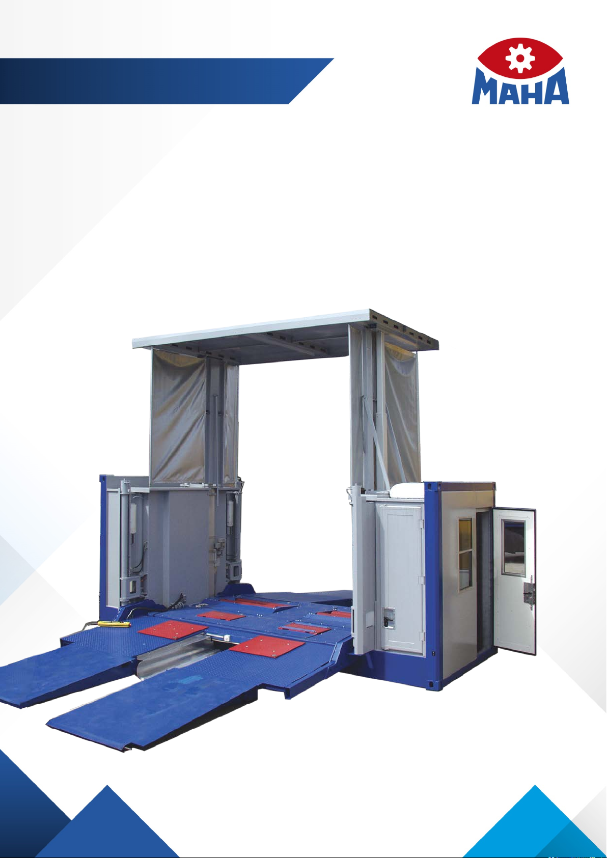
MAHA MTL 15 User manual

Fehler! Verwenden Sie die Registerkarte 'Start', um Name dem Text zuzuweisen, der hier angezeigt werden soll.Fehler! Verwenden Sie
die Registerkarte 'Start', um Name dem Text zuzuweisen, der hier angezeigt werden soll.Fehler! Verwenden Sie die Registerkarte
'Start', um Name dem Text zuzuweisen, der hier angezeigt werden soll.
MTL 15
Mobile Test Container
Original Operating Instructions
BA022901-en
Pos: 1 / Te chn isc he Dokum en tat i on/Br ems pr üf tec hn ik/ MB T-SERIES/022901 Mobile Prüftechnik/022901_002 MTL 15| M obiler Prüfcontainer/BA/Inhalt:0229 Titelbild@ 53\mod_1525240049974_0.docx @ 3032168@ @1
Pos: 1 / Te chnisc he D okum entat ion/Heb etec hnik/ 08 S cher en-Heb eb üh ne n/ 29 0 1 DUO C M/ BA /I n ha lt: 08 29 T ite lb i ld @ 42\mod_1436788474721_0.docx @ 2270230@ @ 1
Pos: 2 / -----F or m at---- -/MAN UEL LE R UM B RUCH Seite numb r uc h @ 0\mod_ 11 3 4403 5 776 87_ 0.d oc x @ 1 277 @ @ 1

2
BA022901-en
Pos: 3 / Te chnisc he D okum entat ion/A lle G erä te/In halte/In ha lt: F irmen-I n for ma ti on MAHA @ 53\mod_1529400378770_75.docx @ 3037518@ @ 1
© MAHA Maschinenbau Haldenwang GmbH & Co. KG
Legal notice based on ISO 16016:
The reproduction, distribution and utilization of this document as well as the communication of its
contents to others without explicit authorization is prohibited. Offenders will be held liable for the
payment of damages. All rights reserved in the event of the grant of a patent, utility model or de-
sign.
The contents of this edition have been checked with great care. However, errors cannot be fully
excluded. Subject to technical change without notice.
Document
Document No.: BA022901-en
Approval Date: 2018-10-12
Manufacturer
MAHA Maschinenbau Haldenwang GmbH & Co. KG
Hoyen 20
87490 Haldenwang
Germany
Phone: +49 8374 585 0
Fax: +49 8374 585 590
Mail: maha@maha.de
Web: http://www.maha.de
Service
MAHA Service Center
AutomoTec GmbH
Maybachstraße 8
87437 Kempten
Germany
Phone: +49 8374 585 100
Fax: +49 8374 585 491
Mail: service@automo-tec.com
Web: www.automo-tec.com
Pos: 4 / -----F or m at---- -/MAN UEL LE R UM B RUCH Seite numb r uc h @ 0\mod_ 11 3 4403 5 776 87_ 0.d oc x @ 1 277 @ @ 1

3
BA022901-en
Pos: 5 / -----F or m at---- -/In ha ltsv er z eic hn is - 3 Eb e ne n @ 5\mod _ 11 688 67 441 0 46_ 75. do cx @ 72 9 20 @ @ 1
Contents
1
Safety.................................................................................................................. 5
1.1 Symbols and Signal Words ......................................................................................5
1.1.1 Personal Injury..........................................................................................................5
1.1.2 Property Damage.....................................................................................................5
1.1.3 Information...............................................................................................................5
2
Description .......................................................................................................... 6
2.1 General ....................................................................................................................6
2.2 Overview..................................................................................................................8
2.3 Technical Data .........................................................................................................8
2.4 Office .....................................................................................................................10
2.5 Generator Room ....................................................................................................10
2.6 Hydraulic Box.........................................................................................................10
2.7 Electrical Control Cabinet .......................................................................................10
2.8 Ramps ...................................................................................................................10
2.9 Protective Roof ......................................................................................................11
2.10 Hydraulic Supports.................................................................................................11
2.11 Test Equipment......................................................................................................11
2.12 Control and Display Elements.................................................................................11
2.12.1 Operating Unit in the Office.....................................................................................11
2.12.2 Cable Remote Control............................................................................................12
2.13 Operating Panel Connection Diagram.....................................................................13
3
Test Container Setup ......................................................................................... 14
Pos: 6 / -----F or m at---- -/MAN UEL LE R UM B RUCH Seite numb r uc h @ 0\mod_ 11 3 4403 5 776 87_ 0.d oc x @ 1 277 @ @ 1

4
BA022901-en
Pos: 7 / -----F or m at---- -/MAN UEL LE R UM B RUCH Seite numb r uc h @ 0\mod_ 11 3 4403 5 776 87_ 0.d oc x @ 1 277 @ @ 1

5
BA022901-en
Pos: 8 / Te chnisc he D okum entat ion/A lle G erä te/Üb erschr ifte n/Übers chr iften 1/ S/ Überschr ift 1: Sich erhei t @ 6\mod_1174482399906_75.docx@ 76962@ 1 @ 1
1
Safety
Pos: 9 / Te chn isc he Dokum en tat i on/A ll e G er ä te/I n halte/ S ic her he it/I nha lt : Ei nf ühr u ng S iche r hei t_ 12p t @2 5\mod_1324455248318_75.docx@ 1138886@ @1
Thoroughly read this manual before operating the equipment and comply with the
instructions. Always display the manual in a conspicuous location.
Personal injury and property damage incurred due to non-compliance with these
safety instructions are not covered by the product liability regulations.
Pos: 1 0 / Tec hn isch e Dokume nt at ion/ Bremsprüftechnik/MBT-SERIE S/0 22 901 M obi le Prüftec hni k/ 0 229 01_ 0 02 M TL 1 5 | Mob iler Prüfcon ta iner /B A/ Inha lt : S ic her he its hinw e ise in d er BAd es jeweil igen Prüfgeräts b eachten @ 5 3\mod_1525250580711_75.docx@ 3032494@ @ 1
Please observe the safety information included in the detailed operating instruc-
tions of the respective test equipment.
Pos: 11.1 /Tec hnische Dokume ntation/Al le Geräte/Über schriften/ Überschri ften 1.1/S/Über schrift 1.1: Symb ole und Signa lwörter @ 50\mod_1503314612825_75.docx@ 2923200@ 2 @ 1
1.1
Symbols and Signal Words
Pos: 11.2 /Tec hnische Dokume ntation/Al le Geräte/Über schriften/ Überschri ften 1.1.1/P /Überschr ift 1.1.1: Pers onenschäde n @ 50\mod_1503389040316_75.docx@ 2923708@ 3 @ 1
1.1.1
Personal Injury
Pos: 11.3 /Tec hnische Dokume ntation/Al le Geräte/Inh alte/Sich erheit/Inhal t:S ymbole und Signa lwörter - Perso ne nsc häd en @ 50\mod_1503389427470_75.docx @ 2923852@ @1
DANGER
indicates an immediate hazard which, if not avoided, will result in death or severe
personal injury.
WARNING
indicates a potential hazard which, if not avoided, could result in death or severe
personal injury.
CAUTION
indicates a potential hazard which, if not avoided, could result in moderate or mi-
nor personal injury.
Pos: 11.4 /Tec hnische Dokume ntation/Al le Geräte/Über schriften/ Überschri ften 1.1. 1/P /Üb er s c hr if t 1 .1 .1 : P r od ukt-, M as chin en-, Anlagenschäden @ 50\mod_1503389109661_75.docx@ 2923756@ 3 @ 1
1.1.2
Property Damage
Pos: 11.5 /Tec hnische Dokume ntation/Al le Geräte/Inh alte/Sich erheit/Inhal t:S ymbole und Signa lwörter - Produk ts c häde n @ 50\m od_1 50338 95466 28_ 75.docx @ 292 3899 @ @ 1
NOTICE
indicates a potentially harmful situation which, if not avoided, could result in dam-
age to the equipment or surrounding objects.
Pos: 11.6 /Tec hnische Dokume ntation/ Alle Geräte/Üb erschrift en/Überschr iften 1.1.1/ I/Überschr ift 1.1.1: Infor mationen @ 50\mod_1503389229939_75.docx @ 2923804@ 3 @ 1
1.1.3
Information
Pos: 11.7 /Tec hnische Dokume ntation/Al le Geräte/Inh alte/Sich erheit/Inhal t:S ymbole und Signa lwörter - Infor ma tio nen @ 50\mod_1503389660901_75.docx @ 2923946@ @1
indicates important information notes.
Pos: 1 2 /----- Form a t-----/ MA N UE L LE R UM BR UC H S e i ten um b r uch @ 0\m od_1134403577687_0.docx @ 1277@ @ 1

6
BA022901-en
Pos: 1 3 / Tec hn is ch e Dokume nt at ion/ Br ems pr üft ec hn ik/ MB T-SE RIE S/ 0 22 901 M ob ile Prüf te ch ni k/ 022 9 01_ 0 02 M T L 1 5 | Mob ile r Prüfc on ta ine r/ B A/ Inha lt : 0229 M TL 15 k om ple tt @ 5 3\mod_1523944918725_75.docx@ 3028798@12222222222211221@ 1
2
Description
2.1
General
The test container is designed for 1-man operation and is set up in a ready-to-use
state in 15 minutes. It is used to check trucks, cars and vans with an axle load of
up to max. 15 t. Depending on the equipment, different vehicle functions, such as
exhaust values, braking, engine power, wheel geometry, etc., can be tested.
Please refer to the operating instructions for the respective tester to find out how
to carry out a test.
DANGER
Operation of the mobile test container during a storm is prohibited due to the risk
of lightning striking!
NOTICE
The roof must be cleared before start-up in the event of snow load!
Climatic conditions
Ambient temperature -10°C to +45°C
Humidity 100%
Max. wind speed 6 on the Beaufort scale
Max. snow load on the lifting roof 60 kg/m2(see safety note above)
Use during a storm Impermissible (see safety note above)
Installation site requirements
•Substrate
Solid, load-bearing substrate such as concrete or pavement; asphalt suitable un-
der certain conditions (depending on the temperature)
•Contact with the ground, torsion
The test container must be installed so that it is torsion-free. The frame and the
ramps must be completely on the ground. Compensate for a lack of support with
support plates.

7
BA022901-en
Contact between the frame and ramp, evenness
The ramps may not be in contact with the bottom edge of the frame. Maximum
permissible ramp angle relative to the frame: -5°
Evenness if the mobile test container has ramps
•Incline (horizontal)
Maximum permissible deviation from the horizontal plane: ±1%
Max. permissible incline in the case of the mobile test container

8
BA022901-en
2.2
Overview
2.3
Technical Data
Dimensions
Length 6,053 mm
Width 2,437 mm
Height 2,587 mm
Weight (ready for operation) approx. 12,500 kg
Fastening fittings for freight containers
Standard ISO 1161
Top JOST CC297 TL, CC 298 TR
Bottom JOST CC299 BL, CC 300 BR

9
BA022901-en
Support feet
System Electro-hydraulic with cable remote control
Support feet lifting height 1,307 mm
Min. drive-through width 2,590 mm (DIN 70014 and DIN EN 284)
Greatest support equipment width 3,200 mm
Greatest support equipment length 4,373 mm
Test chamber (lifting roof)
Drive-through width 3,625 mm
Drive-through height, roof extended 4,287 mm
Drive-through height, roof retracted 1,955 mm
Min. – max. track width 880 – 2,600 mm
Lifting roof system 2 hydraulic cylinders
Lifting roof protection Hydraulic, unlockable non-return valves
Panelling
Chequer plate, EN 10025 S235JRG2, 5 mm thick + 1 to 2 mm chequer height
Drive-on ramps with granulate coating
Power supply
Power supply 3 x 380 V, 50 Hz
Mains connection or integrated power unit
Overload and overvoltage protection
Operating materials
Hydraulic oil HVI 32 approx. 150 l
For the technical data of the floor assemblies, please refer to the operating instruc-
tions for the respective tester.

10
BA022901-en
2.4
Office
•1-man office
•Approx. 2 m² floor space
•Desk
•Lighting with light switch
•230 V electrical connections
•Cashier window
•Door lockable, insulated, incl. ventilation slots
•Sliding door between office and test area
•Chequer plate floor covering
2.5
Generator Room
•Room for generator (optional)
•Hinged doors (to be folded upwards) with gas spring, lockable
•Air inlet for cooling air
•Air outlet for exhaust air
•Soundproof
•Electrical connection for external supply
2.6
Hydraulic Box
•Hinged doors (to be folded upwards), lockable
•Room for hydraulic unit
•Soundproof
2.7
Electrical Control Cabinet
•Hinged doors (to be opened at the side), lockable
•400 V control cabinet
2.8
Ramps
•Steel structure with granulate coating in the driving area
•Fold out using lifting tool
•Plastic rollers
•Rollers can be disassembled when folded out
•Ramps’ load-bearing capacity up to an axle load of max. 15 t
•Retract the ramps using hydraulic cylinders
•Retracted ramp locked using 2 spring bolts

11
BA022901-en
2.9
Protective Roof
•Can be raised hydraulically
•Roof safety support using hydraulic valve
2.10
Hydraulic Supports
•Hydraulic supports for lifting and lowering the container for loading purposes
2.11
Test Equipment
Possible built-in devices:
•Dynamometer
•Brake testing for vehicles with an axle load of up to 15 t
•Chassis tester
•Axle play tester with inspection area for testers (creeper)
•Speedometer test stand
•Short-stroke lift for cars
•Side slip tester
2.12
Control and Display Elements
2.12.1
Operating Unit in the Office
From top to bottom:
•MAHA main switch (– Q1)
for switching the MAHA test equipment on
and off
•<EMERGENCY OFF> mushroom button
(red)
•<MAINS ON> indicator light (white)
•<RESET> pushbutton (blue)
•<DRIVE ONTO TEST STAND> indicator
light (white)
•<LOCK DOOR> pushbutton + indicator
light (white)
•<UNLOCK DOOR> pushbutton (black)
(Also see the “Description > Control and Dis-
play Elements > Cable Remote Control” sec-
tion)

12
BA022901-en
2.12.2 Cable Remote Control
<EMERGENCY OFF> mushroom button (red)
The emergency off switch is used to quickly switch off the entire control if a
hazard occurs. Once this button has been pressed, the <FAULT> indicator
light lights up. The system’s ready for operation state is restored by turning
the mushroom button to the right.
<MAINS ON> indicator light (white)
Lights up as soon as the power supply was switched on and the PLC is ready
for operation.
<FAULT> indicator light (red)
Lights up when a fault is present:
Oil shortage in the hydraulic unit (continuous light)
Fuse failure in the control cabinet (continuous light)
Approval not given for support feet or ramps (flashing light)
<RESET> pushbutton (blue)
Used to acknowledge emergency off.
<RETRACT SUPPORT FOOT 1 – 4> pushbutton (green)
Used to jointly retract support feet 1 – 4.
<EXTEND SUPPORT FOOT 1 – 4> pushbutton (green)
Used to jointly extend support feet 1 – 4.
[Not assigned]
<LEFT / RIGHT RAMPS> ROTARY SWITCH (black)
Left ramps (entrance) active
Position 0
Right ramps (exit) active
<RETRACT RAMPS> pushbutton (green)
Used to retract (lift) the lamps.
<EXTEND RAMPS> pushbutton (green)
Used to extend (lower) the ramps.
<RAISE LIFTING ROOF> pushbutton (green)
Used to lift the lifting roof.
<LOWER LIFTING ROOF> pushbutton (green)
Used to lower the lifting roof.

13
BA022901-en
2.13
Operating Panel Connection Diagram
Brake tester antenna
Axle play tester antenna
Radio receiver
Counter rotation
Roller heating
Noise level meter
Emission testers
Simultaneous display

14
BA022901-en
3
Test Container Setup
NOTICE
•Before every commissioning operation, check that
the raising and lowering range of both the container and the lifting roof
the swivel range of the ramps and their drive elements
are free from obstacles.
•The lifting roof cannot be walked on! Remove snow and dirt from the lifting
roof.
For removal, carry out the steps in these assembly instructions in reverse.
IMPORTANT: In the case of removal, do not charge the unit area towards the
transport vehicle’s driver’s cab!
1 Position the transport vehicle incl. container in the location and secure against
rolling away. Loosen all four container locks.
2 Check the container’s lowering range and remove objects which are
underneath the container.
3 Open the unit area’s tailgate (image
on the right) and perform the follow-
ing work steps:
a. Plug in the cable remote control
(control panel).
b. Establish the power supply via the
unit or a fixed connection.
c. Switch on the main switch (position
1).
d. Have the eight ramp rollers with
safety splint ready in the ramp area.

15
BA022901-en
NOTICE
•Ensure under all circumstances that the connected mains supply has:
three 230 / 400 V AC phases,
one N neutral conductor,
one PE ground conductor and
one clockwise rotating field.
•Ensure that the pin assignment is correct, otherwise the test container cannot
be operated, because a phase monitoring relay is installed in the control cabi-
net.
•The external power supply may only be used with a residual current circuit
breaker.
4a. Check the clearance of the lifting roof’s lifting range.
b. Start the cable remote control (emergency off switch is pointing upwards and
is unlocked).
c. Raise the lifting roof min. 30 cm with the <RAISE LIFT-
ING ROOF> button (green).
5a. Push the polyamide slider upwards
in the support.
b. Loosen the locking handle.
c. Swivel the support arm out 90°.
d. Close the locking handle and man-
ually check the support locking.
e. Carry out the process on all sup-
ports.
NOTICE
If the support feet are not locked at 90°, the hydraulic cylinders’ piston rods can-
not be retracted.
6a. Start the cable remote control (emergency off switch is
pointing upwards and is unlocked).
b. Check the support feet’s lowering range.
c. If there is sufficient clearance, extend the support feet
with the <EXTEND SUPPORT FOOT 1 – 4> button
(green).

16
BA022901-en
7 Drive the transport vehicle away without any contact under the container.
8 Check the container’s lowering range again and remove any objects if
necessary.
DANGER
•It is prohibited to remain underneath the raised container.
•The container may only be raised for loading purposes.
•Maintenance and repairs of any kind under the raised container are prohibited.
•The test container’s lowering range must be examined by the operator during
the lowering process.
9 Fully retract the support feet with the <RE-
TRACT SUPPORT FOOT 1 – 4> button
(green) and thereby lower the container.
10 Raise the center ramp plate and set it to
one side.
11a.
Loosen the lock on all ramps (two per ramp =
four per side).

17
BA022901-en
b. Assemble all eight ramp rollers and secure
with the safety splint.
DANGER
•Two people are required under all circumstances during the next work pro-
cess.
•When extending and retracting the ramps, it must be guaranteed that the op-
erator holding the cable remote control can see the ramps actuated.
•Unauthorised persons are not permitted to remain in the danger zone.
12 Person 1:
a. Attach the pull lever between the
two ramps and pull both ramps
outwards.
b. Set down the pull lever.
13 Person 2:
a. Select the ramp side to be extended with the <LEFT /
RIGHT RAMPS> ROTARY SWITCH (black).
b. Fully lower the ramps onto the ground with the <EXTEND
RAMPS> button (green).

18
BA022901-en
14 Raise the ramps with the pull lever,
remove all the rollers and store
them in a safe place.
CAUTION
In the joint area, the ramps must be firmly on the ground, otherwise driving onto
the ramp is not permitted.
14 Extend all spindle supports (three
per side) as far as the ground.
Tool(s) required:
Long extension
1/2” ratchet
15 Raise the lifting roof fully with the <RAISE LIFTING
ROOF> button (green).
16 Deposit the cable remote control in the container.
CAUTION
The following settings must be checked on the remote control:
•Emergency off switch unlocked
•<LEFT / RIGHT RAMPS> ROTARY SWITCH (black) in the neutral position
Leave the remote control plugged in!

19
BA022901-en
17 Switch off the main switch in the
power unit compartment.
18 Unscrew the side slip tester’s
transport lock screw and store it in
a safe place.
19 Set up and connect the testers as required (also see the “Description >
Operating Panel Connection Diagram” section).
a. MLT 1000 headlight tester:
Autonomous, does not need any connection.
b. MLT 3000 headlight tester:
Can be connected to an MLT 3000 PC Bluetooth module. Bluetooth USB
receiver connection at USB 1. Cable connection is not taken into account.
c. 3M SE-402 noise level meter:
Connected at the control panel.
d. MET 6; MDO2-LON; MGT 5 emission testers:
Can be connected using a USB WLAN adapter or using an Ethernet interface
with a cable connection (equipment cart).
e. Simultaneous displays:
Connected using the bottom Harting connector.

20
BA022901-en
20 Switch on the main switch in the
power unit compartment.
21 <FAULT> indicator light (A) lights
up.
Acknowledge with the blue <RE-
SET> pushbutton (B) on the remote
control or in the office.
22 Switch on the MAHA main switch (C) in the
test container’s office.
23 The door between the office and the test
stand must be locked before testing the
vehicle. To do this, press the <LOCK
DOOR> pushbutton until the white indica-
tor light (D) lights up.
The test stand is ready for operation.
If the door between the office and test stand is open and the roller brake tester is
being driven onto at the same time, testing is not possible and the EUROSYSTEM
software shows the “Pit safety” error message.
Remedy: Drive the vehicle off the roller set, close and lock the door, and
acknowledge the error message with the blue <RESET> pushbutton.
=== Ende d er Lis te für Textmar ke Inha lt= ==
A
B
C
D
Table of contents
Other MAHA Test Equipment manuals