Page 4
AC Voltage Test
• Connect meter terminals Eand Pto the output of a precision AC voltage source.
• Apply the AC voltage listed in Table 2, steps 1 - 3.
• If the display reading falls outside of the limits shown in Table 2, the meter does not meet specification.
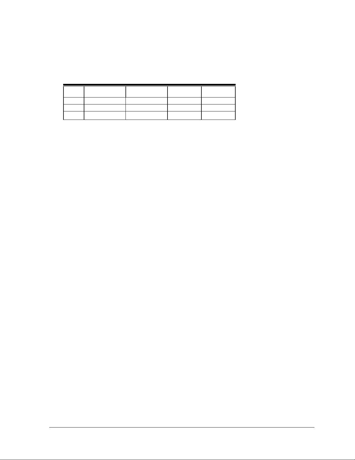
Table 2. AC Voltage Test
Steps Range Input Low Limit High Limit
1 Earth Voltage 12V @ 60Hz 11.7 12.3
2 Earth Voltage 120V @ 60Hz 118.6 121.4
3 Earth Voltage 190V @ 60Hz 187.9 192.1
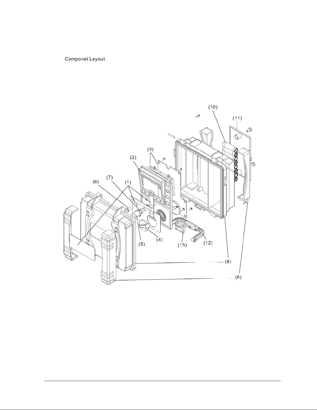
Disassembly Instructions and Setup for Calibration (refer to Figure 3)
• Start with the unit top case lid closed.
• From the bottom, remove the battery cover.
• Remove the 2 screws that hold the measurement unit into the case.
• One screw is in the top right corner of the battery compartment and one screw is in the
lower right, just left of the fuse.
• Replace the battery cover and loosely tighten the screws.
• Open the case and carefully lift the unit from the case. There are several sets of wires attached to the
bottom case so be very careful not to damage them.
• You should now have access to the main circuit board and adjustments.
Calibration
Qualified personnel should only perform calibration procedures described in this manual.
During this calibration it will be necessary to have the electronics of the instrument exposed.
A potential for hazardous voltage can be present during this procedure. Use extreme caution.
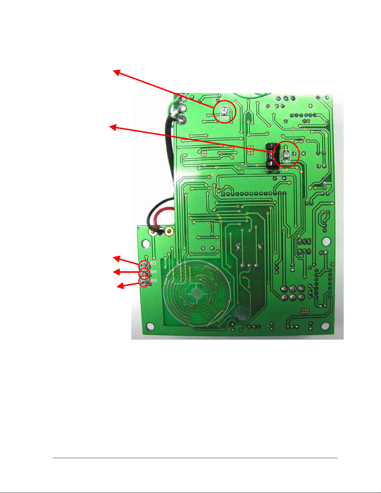
ACV Adjustment (refer to Figure 2)
Turn the function switch to EARTH VOLTAGE position.
• Press and lock the TEST button. The display should read AC 00.0V.
• Set the precision AC power source to standby with an output of 100V @ 60 Hz.
• Connect terminals Eand Pof the 61-796 to the output of the AC source. (Cshould be left open.)
• Energize the AC source.
• Adjust VR6 on the circuit board for a display reading of AC 100.0V.
• Change the AC source to 190V @ 60Hz.
• Displayed should be 190V ±1.5V.
• Maximum allowable error during calibration should not exceed ±0.7% reading ±2 digits.
• Release the TEST button. Turn off AC source and remove test leads. ACV calibration is complete.
Frequency Adjustment (refer to Figure 2)
• Turn the function switch to 20Ωrange.
• Connect a frequency counter to terminals Eand P.
• Press and lock the TEST button and adjust VR1 for a frequency output of 820Hz ±15Hz
(805Hz~835Hz).
• Release the TEST button and remove the counter. Frequency adjustment is complete.
Form number TM61796 Rev 2 May 2008