TPI Scope Plus User manual

42
TABLE OF CONTENTS
page
A. INTRODUCTION
1. Congratulations . . . . . . . . . . . . . . . . . . . . . . . . . . . . . . .3
2. Product Description . . . . . . . . . . . . . . . . . . . . . . . . . . . .3
3. Declaration of Conformity . . . . . . . . . . . . . . . . . . . . . . .4
B. SAFETY CONSIDERATIONS . . . . . . . . . . . . . . . .5
C. TECHNICAL DATA
1. Features and Benefits . . . . . . . . . . . . . . . . . . . . . . . . . .7
2. Specifications . . . . . . . . . . . . . . . . . . . . . . . . . . . . . . . .8
D. MEASUREMENT TECHNIQUES
1. Controls and Functions . . . . . . . . . . . . . . . . . .13
2. Step by Step Procedures:
a) Measuring DC Volts . . . . . . . . . . . . .15
b) Measuring AC Volts . . . . . . . . . . . . .16
c) Measuring DC Amps . . . . . . . . . . . .17
d) Measuring AC Amps . . . . . . . . . . . .18
e) Measuring Resistance . . . . . . . . . . .19
f) Measuring Diodes . . . . . . . . . . . . . .20
g) Continuity Buzzer . . . . . . . . . . . . . .21
h) Measuring Capacitance . . . . . . . . . .22
i) Measuring Frequency . . . . . . . . . . .23
j) Component Test . . . . . . . . . . . . . . .24
k) Logic Test . . . . . . . . . . . . . . . . . . . .26
E. SPECIAL DMM FEATURES & FUNCTIONS . . . .27
F. D MODE FEATURES & FUNCTIONS . . . . . . . . .29
G. WAVEFORM MEMORY & SETUP MEMORY . . .32
H. NORMAL MODE 440 APPLICATIONS . . . . . . . .35
I. TREND MODE 440 APPLICATIONS . . . . . . . . . .38
J. GLITCH CAPTURE 440 APPLICATIONS . . . . . .39
K. ACCESSORIES . . . . . . . . . . . . . . . . . . . . . . . .40
L. MAINTENANCE . . . . . . . . . . . . . . . . . . . . . . . .41
M. RS-232C INTERFACE . . . . . . . . . . . . . . . . . . . .42
N. TROUBLE SHOOTING GUIDE . . . . . . . . . . . . . .44
www. .com information@itm.com1.800.561.8187

5
A. INTRODUCTION
1. Congratulations!!
Thank you for purchasing TPI brand products. The
product you have just purchased in an innovative
new concept in Digital Oscilloscope/Multimeter
design – The Scope Plus. This hand-held meter is
easy to use and is built to last. It is backed by a
three (3) year limited warranty.
2. Product Description
The TPI 440 is a hand-held oscilloscope plus
autoranging DMM. The instruments large, backlit
LCD display shows a reading and waveform simul-
taneously. In addition to the standard functions of
ACV, DCV, ACA, DCA, Ω, Diode Test and Continuity
Buzzer; the 440 measures Frequency (Hz),
Capacitance, Logic and Component test functions.
The 440 also has RS232 output and software for
interfacing with a PC is offered as an optional
accessory.
The 440 comes complete with the following
accessories:
• 440 instrument
• Rechargeable batteries
• Set of standard test leads
• Charger/adapter
• Operating instructions
3
www. .com information@itm.com1.800.561.8187

64
3. EC Declaration of Conformity
This is to certify that model 440 conforms to the protection
requirements of the council directive 89/336/EEC, in the
approximation of laws of the member states relating to
Electromagnetic compatibility and 73/23/EEC, The Low
Voltage Directive by application of the following standards:
EN 50081-1 1992 Emissions Standard
EN 50082-1 1992 Immunity Standard
EN61010-1 1993 Safety Standard
EN61010-2-031 1995 Safety Standard
To ensure conformity with these standards, this instrument
must be operated in accordance with the instructions and
specifications given in this manual.
CAUTION:
Even though this instrument complies with the
immunity standards, the accuracy can be affect-
ed by strong radio emissions not covered in the
above standards. Sources such as hand held
radio transceivers, radio and TV transmitters,
vehicle radios and cellular phones generate
electromagnetic radiation that could be induced
into the test leads of this instrument. Care should
be taken to avoid such situations or alternatively,
check to make sure that the instrument is not
being influenced by these emissions.
www. .com information@itm.com1.800.561.8187

75
B. SAFETY CONSIDERATIONS
WARNING: Please follow manufacturers test procedures
whenever possible. Do not attempt to measure unknown
voltages or components until a complete understanding
of the circuit is obtained.
GENERAL GUIDELINES
ALWAYS
• Test 440 before using to ensure proper operation.
• Inspect the test leads before using to make sure there
are no breaks or shorts.
• Double check all connections before testing.
• Have someone check on you periodically if working
alone.
• Have a complete understanding of the circuit being
measured.
• Disconnect power to the circuit, then connect the test
leads to the 440, then to the circuit being measured.
NEVER
• Attempt to measure unknown high voltages.
• Attempt to measure current with the meter in parallel to
the circuit.
• Connect the test leads to a live circuit before setting up
the instrument.
• Touch any exposed metal part of the test lead assembly.
!
www. .com information@itm.com1.800.561.8187

86
INTERNATIONAL SYMBOLS
DANGEROUS VOLTAGE
AC (ALTERNATING CURRENT)
DC (DIRECT CURRENT)
REFER TO INSTRUCTION MANUAL
GROUND
FUSE
DOUBLE INSULATION
EITHER DC OR AC
!
www. .com information@itm.com1.800.561.8187

97
C. TECHNICAL DATA
1. Features and Benefits
Approvals Meets CE and IEC 1010 requirements.
True RMS Needed to accurately measure non-sinusoidal AC
voltage and current waveforms found on many controls
and circuits.
Auto Set 440 automatically sets-up the scope depending on the
magnitude of the signal being measured.
Real Time Tracks events as they happen.
Update
Glitch Finds spikes in signals.
Capture
Relative LCD displays the difference between the measured
Mode value and a stored value.
Trend Mode Graphs signals to find problems with circuits.
Record Records Min/Max and Average values. Time reference
Mode when value was obtained.
Compare Compares stored value with measured value for
Mode matching components.
Relative % Displays measured value as a percentage of stored
Mode value for checking component tolerances.
RS232 Output Transfers data directly to a PC while measuring.
Back Light Allows viewing in any light condition.
Autorange Automatically selects best range for measurement.
Low Battery Battery should be charged when battery symbol
Indication displays on LCD.
www. .com information@itm.com1.800.561.8187

108
2. Specifications
IEC 1010 Over Voltage:
CAT II - 1000V
CAT III - 600V
Pollution Degree 2
OSCILLOSCOPE FUNCTIONS
Horizontal
Sample Rate 20 Megasamples/second
Record Length 256 in all modes(pixel).
Samples/Division 20
Update rate Real time.
Modes Single shot
Accuracy ±0.01%
Sweep Rate 1µS to 1S in 1,2,5 sequence
Vertical
Bandwidth 1 MHz
Resolution 8 Bits
Channels Single
Coupling AC, DC
Input Impedance 1.11 M Ohm
Accuracy ±3%
Max. Input Volts 1000 Vp-p
www. .com information@itm.com1.800.561.8187

119
OSCILLOSCOPE FUNCTIONS (cont.)
Triggering
Type Internal
Coupling AC, DC, Glitch Capture
Slope + or - edge
Internal Trigger 2/20 Division
Sensitivity
Other
Glitch Capture Over 0.05 Horizontal division,
0.25 Vertical division spike.
Minimum time 1µS.
Digital Trigger 0-512 Samples
Delay Time
Logic Test 3V & 5V CMOS, TTL
Display
www. .com information@itm.com1.800.561.8187
1210
DIGITAL MULTIMETER FUNCTIONS
a. DCV
Range Resolution Accuracy Impedance
400mV 0.1mV ±0.3% of reading, more then 100MΩ
4V 0.001V ±2 digits 10MΩ
40V 0.01V
400V 0.1V
1000V 1V
b1. ACV (20Hz to 50Hz)
Range Resolution Accuracy Impedance
300mV 0.1mV
3V 0.001V ±1.5% of reading, 1.11MΩ
30V 0.01V ±10 digits
300V 0.1V
750V 1V
*NOTICE: Digit fluctuates at AC 20Hz~ 40Hz range. in 1~2 minutes
after input.
b2. ACV (50Hz to 1kHz, 1kHz to 10kHz)
Range Resolution Accuracy Impedance
300mV 0.1mV
3V 0.001V ±0.75% of reading, 1.11MΩ
30V 0.01V ±10 digits
300V 0.1V
750V 1V (N/A for 1kHz to 10kHz)
b3. ACV (10kHz-30kHz, 30kHz-100kHz, 100kHz-200kHz)
Range Resolution 10-30kHz 30-100kHz 100-200kHz Impedance
300mV 0.1mV
3V 0.001V ±2.5% of reading, ±4% of reading, ±10% of reading, 1.11MΩ
30V 0.01V ±30 digits ±200 digits ±300 digits
300V 0.1V
750V 1V N/A N/A N/A
www. .com information@itm.com1.800.561.8187

1311
*Warning: Use only correct size, voltage and current rated fuses.
Test Leads: Use only correct type and overvoltage category rating.
!
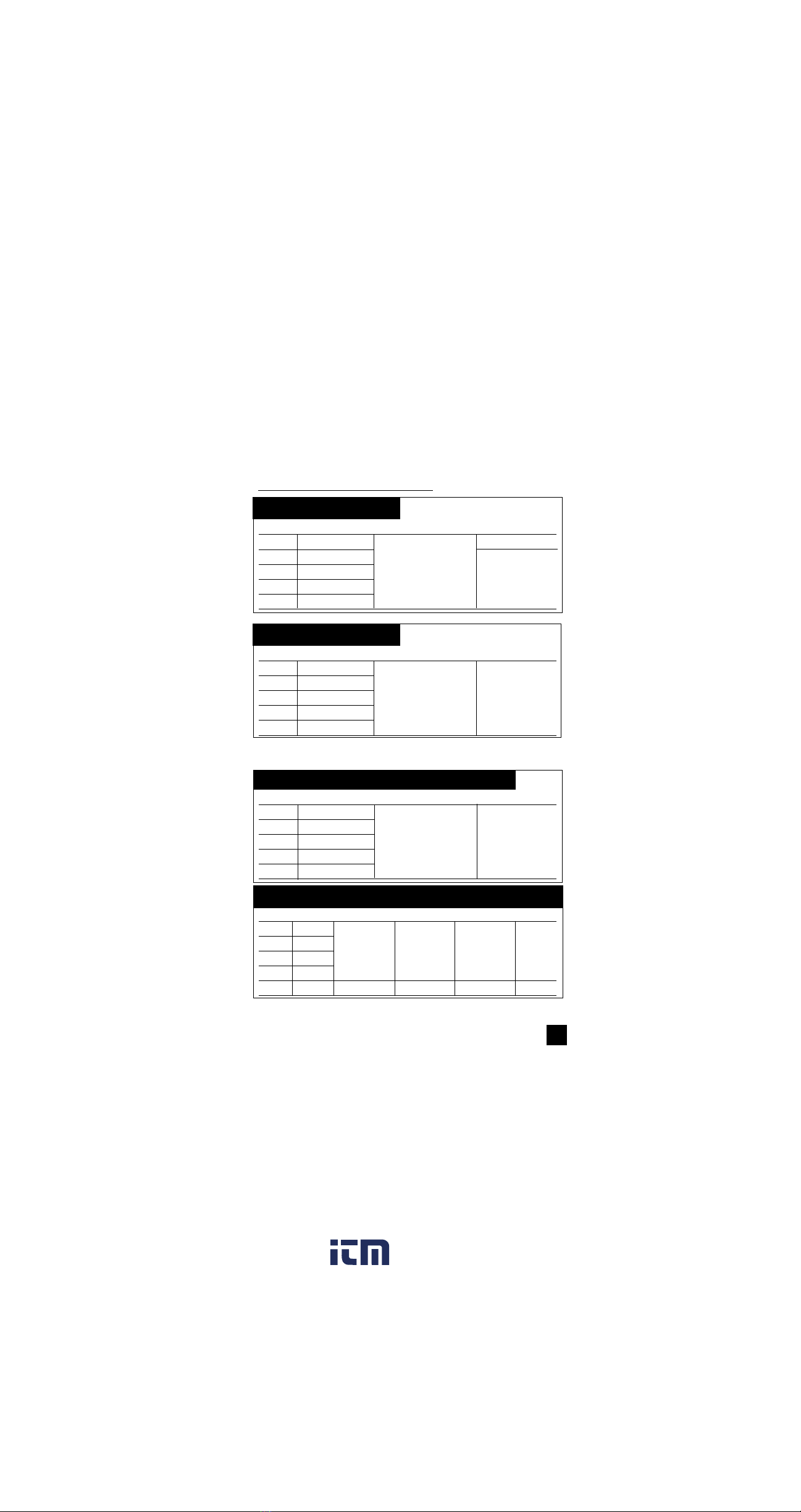
c. DCA
Range Resolution Accuracy Overload
Protection
400µA 0.1µA ±0.5% of reading, ±5 digits Fuse*(fast blow)
4000µA 1µA F600V, 0.5A, 31CM
40mA 0.01mA
400mA 0.1mA
4A 0.001A ±0.75% of reading, ±5 digits F600V, 10A, 31CM
10A 0.01A
d. ACA
Range Resolution 20-50Hz 50Hz-3kHz 3-10kHz 10-30kHz
300µA 0.1µA ±1.0% rdg, ±0.75% rdg, ±2.0% rdg, ±2.0% rdg,
3000µA 1µA ±10 digits ±10 digits ±20 digits ±40 digits
30mA 0.01mA
300mA 0.1mA N/A
3A 0.001A N/A
10A 0.01A
e. OHM (Resistance,Ω)
Range Resolution Accuracy Overload
Protection
400Ω0.1Ω±0. 3% of reading, ±10 digits 600V DC or
4kΩ0.001kΩ±0.3% of reading, AC Peak
40kΩ0.01kΩ±2 digits
400kΩ0.1kΩ
4MΩ0.001MΩ±1.0% of reading, ±10 digits
30MΩ0.01MΩ±1.5% of reading, ±20 digits
f. Continuity Buzzer
Test Voltage Threshold Over Load Protection
3V 100 digits 600 V DC or Peak AC
g. Diode Test
Test Voltage Max Test Current Over Load Protection
3V Approx. 2.5mA 600 V DC or Peak AC
www. .com information@itm.com1.800.561.8187
This manual suits for next models
1
Table of contents
Other TPI Test Equipment manuals


