TPS ProChem R User manual

ProChem_R
TPS Pty Ltd
ABN 30 009 773 371
Phone: (07) 32058027
International: 61 732058027
Email: [email protected]
Web: www.tps.com.au

Congratulations !
Your new proCHEM-R controller is the latest in simple, reliable process
control instrumentation. With correct operation and maintenance, your
proCHEM-R will give you many years of reliable service.
The proCHEM-R is a breeze to operate. This manual has been
designed to help you get started, and also contains some handy
application tips. If at any stage you require assistance, please contact
either your local TPS representative or the TPS factory in Brisbane.
The manual is divided into the following sections:
1. Table of Contents
Each major section of the handbook is clearly listed. Sub-sections
have also been included to enable you to find the information you
need at a glance.
1. Introduction
The introduction has a diagram and explanation of the display and
controls of the proCHEM-R. It also contains a full listing of all of the
items that you should have received with the unit. Please take the
time to read this section, as it explains some of items that are
mentioned in subsequent sections.
1. Main Section
The main section of the handbook provides complete details of the
proCHEM-R, including operating modes, calibration, troubleshooting,
specifications, and warranty terms.
1. Appendices
Appendices containing background information and application notes
are provided at the back of this manual.
2

Contents
1. Introduction 5
1.1 proCHEM-R Illustration 5
1.2 Unpacking Information 8
1.3 Specifications 9
2. Operating Modes 10
3. Installation and Set-up 11
3.1 Connection and Configuration Diagram 11
3.2 Mounting the Enclosure 12
3.3 Mounting the Sensor 13
3.4 Terminal Connections 14
3.5 Setting the Control Limit 16
3.6 Selecting Current or Voltage Output 19
3.7 Selecting Standard or Custom 4 to 20 mA Output 20
3.8 Calibrating the 4 to 20mA Output 21
3.9 CMRR (RV7) Control 21
3.10 Factory Configuration (J3) Jumpers 22
4. Calibration 23
4.1 Calibration Procedure 23
4.2 Calibration Notes 25
5. Process Monitoring 26
6. Automatic Control 26
7. Fuse Replacement 26
8. Troubleshooting 29
8.1 Instrument Function Troubleshooting 29
8.2 Redox Troubleshooting 29
9. Warranty 30
10. Appendices 33
10.1 Power Terminal connections when 12V DC option is fitted 33
10.2 Relay Output Wiring Examples for mains powered units 34
3

1. Introduction
1.1 proCHEM-R Illustration
5

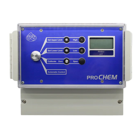
Set Upper Limit Control
Adjust this control to the Millivolt value at which the High LED and
relay output are activated. Factory-set to activate when the reading is
above the Upper Limit. See section 3.5.
High LED
The High LED provides visual indication of when the Upper Limit has
been exceeded. Factory-set to light up when the reading is above the
Upper Limit. See section 3.5.
Set Lower Limit Control
Adjust this control to the Millivolt value at which the Low LED and
relay output are activated. Factory-set to activate when the reading is
below the Lower Limit. See section 3.5.
Low LED
The Low LED provides visual indication of when the Lower Limit has
been exceeded. Factory-set to light up when the reading is below the
Lower Limit. See section 3.5.
Zero Calibrate Control
Adjust this control to calibrate the proCHEM-R in a Redox standard.
See section 4.
Span Calibrate Control
This control is not required for the proCHEM-R.
Function Switch
The Function Switch is used to select the mode of operation. See
section 2.
Display Window
The proCHEM-R has a large, easy to read LCD display. The units of
measurement are clearly shown in the window beneath the display.
Terminal Cover
6

The terminal cover provides easy access to all of the connections,
relay output fuses, configuration jumpers and user-adjustable
trimmers. The cover is water resistant to IP65.
7

1.2 Unpacking Information
Before using your new proCHEM-R, please check that the following
accessories have been included:
Part No
1. proCHEM-R Process Controller 111122
1. ZoBell Redox Standard, 229mV, 200mL ea Part A & Part B
121309
1. proCHEM-R Handbook 130050
Options that may have been ordered with your proCHEM-R:
Dip mounted Redox Sensors, and submersible assembly…
1. Submersible, Non-flow Redox Sensor, 5m 111260
1. Intermediate Junction Redox Sensor, 5m 121267
1. Stainless Steel solution earth rod, 5m 121360
1. Submersible protective housing for Redox & earth rod 111303
Screw-in Redox Sensor, and adaptor for 40mm PVC pipe…
1. Screw-in, Non-flow Redox Sensor, 5m 111262
2. Stainless Steel solution earth rod, 5m (not screw-in) 121360
1. ¼” BSP thread adaptor for 40mm PVC pipe 111305
Instrument options…
1. 4-20mA loop-Rowered, remote LCD 130080
2. 12V DC Power Option 130072
8

1.3 Specifications
Range 0 to 1000 mV
Resolution 1 mV
Accuracy ±1 mV
Linearity ±1 mV
Repeatability ±1 mV
Ambient Drift <0.02% Span per 1OC change
Long term drift<0.1% per year
Input Impedance >3 x 10¹² Ω
Zero Range ±100 mV
Common Mode Rejection 120 dB
Enclosure Polycarbonate, waterproof to IP65
Display 12.7 mm LCD (optional remote 4-20mA loop
powered display available)
Analogue Outputs 4 to 20mA (500 Ohms max. loop resistance )
0 to 1 V DC (min. load 1000 Ω)
0 to 10 V DC optional (min. load 1000 Ω)
Control Outputs 2 x Clean contact changeover relays,
rated to 2A at 240V AC
Isolation Galvanic isolation of sensor input
Power 240V AC, 50/60Hz (120V AC optional)
Dimensions 215 x 190 x 115 mm
Mass Instrument only : Approx 900g
Full Kit : Approx 1.5kg
Operating Environment: Temperature : 0 to 45 oC
Humidity : 0 to 95 % R.H.
9

2. Operating Modes
The function switch is used to select the required mode. The four
operating modes available are…
1. Set Upper Limit : Switch to Set Upper
Limit when setting the Millivolt value at which
the High LED and relay output are activated.
The relay output is not operational in this mode.
Factory-set to activate when the reading is
above the Upper Limit. Can be user set to be a
activate when the reading is below the Upper
Limit. See section 3.5.
2. Set Lower Limit : Switch to Set Lower
Limit when setting the Millivolt value at which
the Low LED and relay output are activated.
The relay output is not operational in this mode.
Factory-set to activate when the reading is
below the Lower Limit. Can be user set to be a
activate when the reading is above the Lower
Limit. See section 3.5.
3. Calibrate : Switch to Calibrate mode to
place the proCHEM-R into standby (eg. when
calibrating). This mode disables the two output
relays to avoid chemicals being added when
placing the sensor into calibration buffers.
4. Automatic Control : Switch to
Automatic Control to enable the Alarm LED’s
and relay outputs. These will be activated when
the Millivolt reading is outside the Upper and
Lower limit values. See section 3.5.
10

3. Installation and Set-up
3.1 Connection and Configuration Diagram
The diagram below is provided as a reference for the terminal
connections, configuration jumpers and user-adjustable trimmers that are
discussed throughout this section.
11

3.2 Mounting the Enclosure
The proCHEM-R can be wall-mounted with 3 screws. Two mounting
points are located underneath the terminal cover, and are positioned so
that they do not affect the waterproofing of the enclosure. The third
mounting point is centrally located near the top of the rear of the
enclosure, and has been designed to hook over a screw-head. The
dimensions for the mounting screw centres are provided on the rear of the
enclosure, and are also illustrated below…
12

3.3 Mounting the Sensor
Mounting the sensors is a very important aspect of the installation, and is
often done incorrectly. In automatic control situations, the sensor should
always be mounted as close as possible to the injection point. This will
cause the sensor to detect the added chemicals immediately, and shut
the addition off until mixing has taken place. For in-line mounting, it is
important that chemicals are injected upstream. Additionally, the line must
be run through a mixing chamber, such as a large drum, to ensure that
the injected chemical has mixed in properly by the time the solution flows
past the sensor. There must always be adequate flow of fresh sample
past the sensor, for accurate monitoring. The diagrams below show
typical mounting arrangements for “dip” mounting and in-line mounting.
Dip Mounting In-line Mounting
1. Injection point close to sensor. 1. Injection point upstream from
2. Submersible housing to protect and close to sensor.
sensors and waterproof rear of 2. Mixing container after injection
cable (part no 111303). and before sensor.
3. Continuous stirring. 3. Redox sensor mounted as close to
vertical as practical.
13

3.4 Terminal Connections
3.4.1 Power Connections
All power connections are on the main terminal block (H1), which has 18
terminals.
Note: The power connections detailed below are for normal mains
power. Refer to section 10.1 for power wiring details when the 12V
DC power option is fitted.
Terminal
No.
Connection
Colour
1
220 / 240V AC Active input
Brown (standard colour)
2
Duplicate 240V AC Active contact.
Brown (standard colour)
3
Duplicate 240V AC Active contact.
Brown (standard colour)
4
220 / 240V AC Earth input
Green (standard colour)
5
Duplicate 240V AC Earth contact.
Green (standard colour)
6
Duplicate 240V AC Earth contact.
Green (standard colour)
7
220 / 240V AC Neutral input
Blue (standard colour)
8
Duplicate 240V AC Neutral contact.
Blue (standard colour)
9
Duplicate 240V AC Neutral contact.
Blue (standard colour)
10
Normally Closed contact of Lower
relay output
Customer Defined
11
Common contact of Lower relay
output
Customer Defined
12
Normally Open contact of Lower
relay output
Customer Defined
13
Normally Closed contact of Upper
relay output
Customer Defined
14
Common contact of Upper relay
output
Customer Defined
15
Normally Open contact of Upper
relay output
Customer Defined
16
No Connection
17
+ve of current or voltage output
Customer Defined
14

18
-ve of current or voltage output
Customer Defined
3.4.2 Sensor Connections
All sensor connections are on the 6-way terminal block which is on the
right hand side of the enclosure.
Terminal
No.
Connection
Colour
1
No Connection
2
No Connection
3
Solution Guard
Customer-defined. Green is
recommended.
4
Redox Shield (if fitted)
Green
5
Redox Reference
Black
6
Redox Signal
Clear or White
15

3.5 Setting the Control Limit
The Upper and Lower control limits can both be set over the full scale of
the proCHEM-R. The unit is set up in the factory for the Upper Limit LED
and relay to be activated when the reading rises above the Upper Limit.
Similarly, the Lower Limit LED and relay are factory set to be activated
when the reading drops below the Lower Limit.
See section 3.5.3 for details on how to re-set the Upper or Lower limits for
the reverse of the default direction.
The hysteresis around the set point can be also be adjusted if necessary.
See section 3.5.4 for an explanation of hysteresis.
3.5.1 Setting the Upper Limit value
1. Switch the proCHEM-R to Set Upper Limit.
The Upper Limit value is now displayed. Note that the Alarm LED and
output relays are now disabled. The 4-20mA or 0-1V outputs are still
active, and proportional to displayed value.
2. Adjust the Set Upper Limit control until the display reads the desired
set point value.
3.5.2 Setting the Lower Limit value
1. Switch the proCHEM-R to Set Lower Limit.
The Lower Limit value is now displayed. Note that the Alarm LED and
output relays are now disabled. The 4-20mA or 0-1V outputs are still
active, and proportional to displayed value.
2. Adjust the Set Lower Limit control until the display reads the desired
set point value.
16

3.5.3 Reversing the default control direction
The Upper Limit control action can be reversed to activate the Upper Limit
LED and relay when the reading drops below the Upper Limit.
Similarly, the Lower Limit control action can be reversed to activate the
Lower Limit LED and relay when the reading rises above the Lower Limit.
Having two Limits acting in the same direction can be very useful for
processes where the readings always drift in one direction. It allows the
operator to set the first Limit as a control point (eg to start a dosing
pump), and the second limit beyond that as an alarm point, in case the
control action was not effective.
The proCHEM-R must be switched OFF before changing jumper settings.
To reverse the action of the Lower Limit, and have two
Limits that activate the High and Low LED’s and relays
when the reading rises above the Limits, set the J3 and
J4 jumpers as shown.
To reverse the action of the Upper Limit, and have two
Limits that activate the High and Low LED’s and relays
when the reading drops below the Limits, set the J3
and J4 jumpers as shown.
To re-set the action of the Upper and Lower limits to
factory defaults, set the J3 and J4 jumpers as shown
17

3.5.4 Adjusting the Hysteresis
The hysteresis is the Redox range over which the alarm/control output
remains switched on, once the trip point has been exceeded.
For example, if the Lower Limit is set to 700mV, with a hysteresis of
10mV, the alarm/control output is switched ON when the reading goes to
690mV (i.e. 700 - 10). The output is not switched OFF until the reading
goes back up to 710mV (i.e. 700 + 10).
The hysteresis stops the relay “chattering” around the set point, by
providing a buffer between the points at which the output is switched ON
and OFF. This feature can significantly increase the life of pumps and
solenoid valves.
The factory-set hysteresis is approximately ±10mV, as in the example
above. The hysteresis can be increased to as high as ±40mV with the
relevant LOWER HYST (RV2) or UPPER HYST (RV4) trimmers in the
terminal area. Turning the trimmer clockwise increases the hysteresis and
turning it anti-clockwise decreases the hysteresis.
TPS DOES NOT recommend that this setting be altered, unless it is
absolutely necessary.
The hysteresis trimmer should only be adjusted a little at time. The
process being controlled should then be closely monitored over a time to
ensure that the desired control is being achieved.
18

3.6 Selecting Current or Voltage Output
The Current/Voltage Output jumpers in terminal section can be user-set
for either 4 to 20mA or 0 to 1V DC output. The proCHEM-R must be
switched OFF before changing jumper settings.
The jumper settings for 4 to 20 mA output are:
The jumper settings for 0 to 1V DC output are:
Note that the spare jumper has been fitted to a spare Current/Voltage
Output jumper pin. This is a safe place to keep it, in case the
proCHEM-R needs to be reset to current output in the future.
19

3.7 Selecting Standard or Custom 4 to 20 mA Output
The proCHEM-R is normally supplied to provide 4 to 20 mA for the full
scale of the readout. If a custom 4 to 20 mA output (eg. 4 to 20 mA output
for 600mV to 800mV) is supplied, the user can still change between this
custom output and the normal 4 to 20 mA output for full scale.
The jumper settings for the standard 4 to 20 mA output
are…
The jumper settings for the custom 4 to 20 mA output
are…
20
This manual suits for next models
1
Table of contents
Other TPS Controllers manuals