BUSCH 0987 209 539 User manual

Get technical data,
instruction manuals,
service kits
Pump Control Instructions
R5 / COBRA
with Variable-Frequency Drive
R5 RA/RC 0630 B/C
COBRA NC 0630 C / NX 0650 A / NX 0950 A
0870208958/-0002_en / Original instructions / Modifications reserved 15/02/2021
Ateliers Busch S.A.
Zone industrielle, 2906 Chevenez
Switzerland

Table of Contents
2 / 44 0870208958_INVEOR_VFD_-0002_PCI_en
Table of Contents
1 Safety .......................................................................................................................................3
2 Introduction..............................................................................................................................4
3 Product Description ..................................................................................................................5
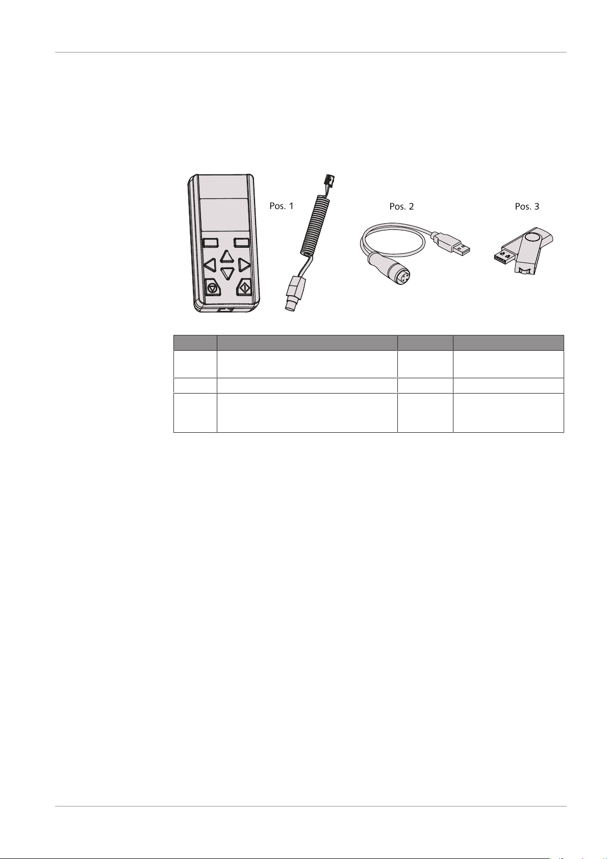
3.1 Scope of Delivery ............................................................................................................. 5
3.2 Application....................................................................................................................... 5
4 Installation................................................................................................................................6
4.1 Remote Control Connection............................................................................................. 6
4.2 PC-Software Installation................................................................................................... 6
5 Commissioning.........................................................................................................................7
5.1 Operate the Remote Control............................................................................................ 7
5.1.1 Key Overview........................................................................................................ 7
5.1.2 Navigation and Input............................................................................................. 7
5.1.3 Menu .................................................................................................................... 8
5.1.4 Parameter Group Menu (Expert Mode) .................................................................9
5.2 Run the Machine.............................................................................................................. 12
6 Custom Parametrisation ...........................................................................................................13
6.1 Disable the Machine......................................................................................................... 14
6.2 Save Parameters............................................................................................................... 15
6.3 Reload Factory Settings .................................................................................................... 17
7 Parameter Description ..............................................................................................................19
7.1 Overview I/O Connections .............................................................................................. 19
7.2 Preventing Electromagnetic Interferences ......................................................................... 21
7.3 NX 0950 A Parameters Set Change Values....................................................................... 22
7.3.1 Description ............................................................................................................ 22
7.3.2 How to know if the machine has two set values ? .................................................22
7.3.3 Parameters not to be changed............................................................................... 22
7.4 Start / Stop Functionality.................................................................................................. 23
7.4.1 Description ............................................................................................................ 23
7.4.2 Parameter’s to Change .......................................................................................... 23
7.5 Fixed Frequency Selection via Digital Inputs ..................................................................... 23
7.5.1 Description ............................................................................................................ 23
7.5.2 Speed Control: 1 Fixed Frequency + Min. Frequency............................................. 24
7.5.3 Speed Control: 3 Fixed Frequency + Min. Frequency............................................. 24
7.5.4 Speed Control: 7 Fixed Frequency + Min. Frequency............................................. 25
7.6 Speed Control via Analogue Input.................................................................................... 26
7.6.1 Description ............................................................................................................ 26
7.6.2 Speed Control via Internal Potentiometer ..............................................................26
7.6.3 Speed Control via Analogue Input 1 ...................................................................... 26
7.6.4 Speed Control via Analogue Input 2 ...................................................................... 29
7.7 PID Process Control.......................................................................................................... 32
7.7.1 Description ............................................................................................................ 32
7.7.2 Change for PID Process Control ............................................................................ 33
7.7.3 Stand-by Function in PID Process Control.............................................................. 35
8 Troubleshooting .......................................................................................................................36
8.1 LED Flash Codes............................................................................................................... 37
8.2 List of Errors ..................................................................................................................... 38

Safety | 1
0870208958_INVEOR_VFD_-0002_PCI_en 3 / 44
1 Safety
These pump control instructions shall give further information concerning individual set-
ting or data analysis to experienced and trained users. Prior to handling the product, this
document should be read and understood. If anything needs to be clarified please con-
tact your Busch representative.
Read carefully before use and keep for future reference.
This document remains valid as long as the customer does not change anything on the
product.
The product is intended for industrial use. It shall be handled only by qualified personnel.
The product has been designed and manufactured according to state-of-the-art meth-
ods.
Nevertheless, residual risks may remain. This instruction manual highlights potential haz-
ards where appropriate. Safety notes and warning messages are tagged with one of the
keywords DANGER, WARNING, CAUTION and NOTICE as follows:
DANGER
... indicates an imminent dangerous situation that will result in death or serious injuries if
not prevented.
WARNING
... indicates a potentially dangerous situation that could result in death or serious injuries.
CAUTION
... indicates a potentially dangerous situation that could result in minor injuries.
NOTICE
... indicates a potentially dangerous situation that could result in damage to property.
NOTE
... indicates helpful tips and recommendations, as well as information for efficient and
trouble-free operation.

2 | Introduction
4 / 44 0870208958_INVEOR_VFD_-0002_PCI_en
2 Introduction
NOTE
Pump control instructions.
This document is delivered along with variable-frequency drive control device.
It only contains information about the variable-frequency drive parametrisation and con-
trol.
Please refer to the original instruction manual of the corresponding machine which con-
tent remains valid.

Product Description | 3
0870208958_INVEOR_VFD_-0002_PCI_en 5 / 44
3 Product Description
3.1 Scope of Delivery
Parameter kit
Kit number: 0987 209 539
Pos. 1 Pos. 2 Pos. 3
Pos. Part Qty Part no.
1 Remote control including cable to vari-
able-frequency drive
1 0987 208 729
2 Cable for PC 1 0987 208 730
3 USB Stick including PC-Software, para-
meter list (factory settings), pump con-
trol instructions
1 0889 209 540
3.2 Application
The parameter kit is intended for:
– Parametrisation of the variable-frequency drive
– Control (e.g. locking and releasing)
– Display of various process values
of the following machines equipped with variable-frequency drive:
– R5 RA/RC 0630 B
– R5 RA/RC 0630 C
– COBRA NC 0630 C
– COBRA NX 0650 A
– COBRA NX 0950 A

4 | Installation
6 / 44 0870208958_INVEOR_VFD_-0002_PCI_en
4 Installation
4.1 Remote Control Connection
NOTICE
Non-compatible variable-frequency drive.
Risk of damage to the variable-frequency drive!
• The remote control must only be operated with „INVEOR“ variable-frequency drive.
M12 interface socket
• Connect the cable of the remote control to the M12 interface socket.
4.2 PC-Software Installation
• Start the setup file of the PC-Software from the USB stick.
• Install the PC-Software on your computer.

Commissioning | 5
0870208958_INVEOR_VFD_-0002_PCI_en 7 / 44
5 Commissioning
5.1 Operate the Remote Control
5.1.1 Key Overview
Confirm buttons
“UP” and “DOWN” buttons
“LEFT” and “RIGHT” buttons
Stop button
Start button
5.1.2 Navigation and Input
Buttons Function
"UP"/"DOWN" buttons Selecting parameters, changing values
"LEFT"/"RIGHT" buttons Navigating cursor
Confirm buttons With these buttons, the command showed
in the display is activated via the button
"START"/"STOP" buttons With these buttons, the motor is started or
stopped
Commands Procedures
Next Calling up parameters and submenu
Back One menu level higher
Cancel End entry without saving
Change Call up edit mode (cursor blinks)
Save Save selection, entry or change
Enter Confirm the selected parameter set
Start Command for motor detection
Enter Procedures
Displaying tens, hundreds, thousands place Press "LEFT" arrow until the desired tens,
hundreds or thousands place is displayed
Displaying decimal places Press "RIGHT" arrow until the desired
decimal places are displayed
Entering negative values Place cursor on the plus sign, select the
minus sign with the "UP" arrow and save

5 | Commissioning
8 / 44 0870208958_INVEOR_VFD_-0002_PCI_en
5.1.3 Menu
The menu appears on the remote control display when the variable-frequency drive is
switched on.
For parameter groups menu, there are two different modes:
– Standard mode:
Contains all necessary parameters for standard application from the factory.
– Expert mode, see Parameter Group Menu (Expert Mode) [►9]:
Contains advanced parameters for special uses, the expert mode is activated in the
main menu.
The remote control always starts in standard mode.
x
x
The INVEOR MMI always starts in standard mode. If the INVEOR MMI is de-
energized, the standard mode is active again.
01. Actual values
02. Parameter group
20. Actual fault
21. Fault memory
30. Automatic Motor detection
40. Control
50. Expert mode
80. Read parameter
81 Write parameter
82 Delete parameter
98. SW/HW status
99. Language
Fig. 5: View of main menu
The entire menu is mapped in the INVEOR operating manual.

Commissioning | 5
0870208958_INVEOR_VFD_-0002_PCI_en 9 / 44
5.1.4 Parameter Group Menu (Expert Mode)
In expert mode, the "0.2 Parameter group" menu contains advanced parameters for
special applications.
Operation
INVEOR MMI / 2013-09 21
3.6 Parameter group menu (expert mode)
In expert mode, the "0.2 Parameter group" menu contains advanced
parameters for special applications. The expert mode is activated in the
main menu (see Fig. 5: View of main menu).
Fig. 8: View of parameter group (expert mode) – Part 1
01.Actual values
Basic parameter Control mode Process controller
Low speed
High speed
Deceleration 1
Acceleration 1
Deceleration 2
Acceleration 2
Ramp selection
Ref.channel
02.Parameter groups
Enable software
Start protect
Rotation direction
Reset
Automatic reset
Quan.auto.reset
Preset speed mode
Preset speed 1
Preset speed 7
MOP digital in.
MOP step range
MOP step time
MOP resp.time
MOP ref.memory
PID prop.gain
PID prop.gain
PID prop.gain
PID feedback
PID inverted
PID preset ref. 1
…
PID preset ref. 1
PID ref.mode
PID standby time
PID std.by hyst.
…

5 | Commissioning
10 / 44 0870208958_INVEOR_VFD_-0002_PCI_en
Operation
INVEOR MMI / 2013-09 22
Fig. 9: View of parameter group (expert mode) – Part 2
ontrol terminal
AI1 ref.type
AI1 min.input
AI1 max.input
AI1 dead time
AI1 filter time
AI1 function
AI1 phy.unit
AI2 ref.type
AI1 min.input
AI2 max.input
AI2 dead time
AI2 filter time
AI2 function
AI2 phy.unit
AO1 function
AO1 min.output
AI1 max.input
DO1 function
DO1 on
DO1 off
DO2 function
DO1 on
DO1 off
Relay1 function
Relay1 on
Relay1 off
Relay1 on delay
Relay1 off delay
Relay2 function
Relay2 on
Relay2 off
Relay2 on delay
Relay2 off delay
Special function
External fault 1
External fault 2
urr.limit.[%]
urr.limit.[s]
Factor gearbox
Stall detection
Stall time
Para. set change
Tech.parameter1
…
Tech.parameter20

Commissioning | 5
0870208958_INVEOR_VFD_-0002_PCI_en 11 / 44
Operation
INVEOR MMI / 2013-09 23
*) These values are automatically determined and entered during motor detection.
Fig. 10: View of parameter group (expert mode) – Part 3
Brake chopper
Brake chopper
Field.parameter
SAS/SPF address
SAS baud rate
Fieldbus address
Fieldbus baud rate
Bus timeout
Fieldbus language
Ref-feed.diff.
Tolerance range
Reference value
Process data out 3
…
Process data out 10
Process data in 3
…
Processdata in 6
Motor type
i2t fac.mot.
I2T time
Opt.stat.resist.
Motor current
Motor power
Motor speed
Motor frequency
Motor resistance *
Leakage induct. *
Motor voltage
Motor cos phi
Holding current time
Stator induct. *
Nominal flux
Controller
t
Control method
Encoder type
Enc.line count
Encoder offset
Flying restart
Switching frequency
Speed control Kp
Speed control Tn
Slip trimmer
Squared charac.
Flux compensation
Motor parameter
Volt.contr.res.
Field weakening
Startup current
Init.time PMSM
Start.mode PMSM
Start.ramp PMSM
Startup frequency

5 | Commissioning
12 / 44 0870208958_INVEOR_VFD_-0002_PCI_en
5.2 Run the Machine
NOTICE
Frequent starts and stops by connecting and disconnecting from the power supply.
Risk of damage to the machine!
Starting the machine by connecting and disconnecting the power supply is permitted
max. 2x per minute. Between disconnecting and connecting at least 10 seconds must
have been passed. If the process requires more frequent starts/stops of the machine:
• Use the digital start signal.
The machine will run at the following fixed speed (factory settings):
Machine type Motor frequency
R5 RA/RC 0630 B 60 Hz
R5 RA/RC 0630 C 60 Hz
COBRA NC 0630 C According to module maximum speed
50 or 60 Hz
COBRA NX 0650 A
COBRA NX 0950 A 72 Hz
• Refer to the original instruction manual of the corresponding machine for the com-
plete commissioning procedure.
• Maximum permissible number of starts by using the digital signal: unlimited
As soon as the machine is operated under normal operating conditions:
• Measure the mains current or read it via PC-Software or controller.

Custom Parametrisation | 6
0870208958_INVEOR_VFD_-0002_PCI_en 13 / 44
6 Custom Parametrisation
DANGER
Maintenance work without disconnecting the variable-frequency drive.
Risk of electrical shock.
• Disconnect and isolate the variable-frequency drive before attempting any work on it.
High voltages are present at the terminals and within the variable-frequency drive for
up to 10 minutes after disconnection of the electrical supply.
• Always ensure by using a suitable multimeter that no voltage is present on any drive
power terminals prior to commencing any work.
DANGER
Carry out any work on the variable-frequency drive and motor.
Risk of electrical shock!
• Electrical installation work must only be executed by qualified personnel.
NOTICE
Change factory settings.
Risk of damage to the machine!
If wrong or not allowed parameters have been set, Busch disclaims any liability for dam-
age to the machine.
• Change only the allowed parameters described in the chapter Parameter Description
[►19].
NOTE
Parameterisation is possible prior to device installation.
Parameterisation can be performed before the drive controller is installed in the motor.
The variable-frequency drive has a 24 V low-voltage input for this purpose, which can
supply the electric system without requiring mains power.

6 | Custom Parametrisation
14 / 44 0870208958_INVEOR_VFD_-0002_PCI_en
6.1 Disable the Machine
• Make sure that the variable-frequency drive is de-energised.
• Remove the bridge between “24V Out” (int. power supply) and “En HW” (enable
hardware) in order to avoid any start up.
• Energise the variable-frequency drive either from 24 VDC power supply or from the
mains power.

Custom Parametrisation | 6
0870208958_INVEOR_VFD_-0002_PCI_en 15 / 44
6.2 Save Parameters
NOTE
Before making any change, backup the current parameters via PC-Software.
• Make sure that the machine is disabled, see Disable the Machine [►14].
• Connect the variable-frequency drive to the computer with the provided cable.
• Start the PC-Software previously installed, see PC-Software Installation [►6].
• Select “Connect”
• Select the communication port of the cable (usually never COM1)
• Press “OK”

6 | Custom Parametrisation
16 / 44 0870208958_INVEOR_VFD_-0002_PCI_en
• Go to “File” → “Save As”
• Save the file “.inveor” in your database in order to reload the initial or specific para-
meters for future purposes.
NOTE
Custom parametrisation via the remote control.
Please keep a note of each changed parameters.
As soon as the parametrisation is finished:
• De-energise the variable-frequency drive.
• Reconnect the variable-frequency drive inputs according to your parameter list
without forgetting to connect the “En HW” input.

Custom Parametrisation | 6
0870208958_INVEOR_VFD_-0002_PCI_en 17 / 44
6.3 Reload Factory Settings
• Make sure that the machine is disabled, see Disable the Machine [►14].
• Connect the variable-frequency drive to the computer with the provided cable.
• Start the PC-Software previously installed, see PC-Software Installation [►6].
• Select “Open” to load the file “.inveor” of your parameter list.
• Click on “Write”.
• Select the communication port of the cable (usually never COM1)
• Press “OK”

6 | Custom Parametrisation
18 / 44 0870208958_INVEOR_VFD_-0002_PCI_en
• Wait until the end of the program downloading.
• Check the motor parameters match to the motor fitted on the machine.
As soon as the parametrisation file is loaded:
• De-energise the variable-frequency drive.
• Reconnect the variable-frequency drive inputs according to your parameter list
without forgetting to connect the “En HW” input.

Parameter Description | 7
0870208958_INVEOR_VFD_-0002_PCI_en 19 / 44
7 Parameter Description
DANGER
Carry out any work on the variable-frequency drive and motor.
Risk of electrical shock!
• Electrical installation work must only be executed by qualified personnel.
NOTICE
Change factory settings.
Risk of damage to the machine!
If wrong or not allowed parameters have been set, Busch disclaims any liability for dam-
age to the machine.
• Change only the allowed parameters described in the chapter Parameter Description
[►19].
NOTICE
Changing of any other parameters than described below.
Risk of damage to the machine!
• Do not change any other parameter than described below.
7.1 Overview I/O Connections
Terminals Plug terminal clamp with activation button
(slot screwdriver, max. width 2.5 mm)
Connection cross section 0.5 to 1.5 mm2, single-wire, AWG 20 to AWG 14
Connection cross section 0.75 to 1.5 mm2, fine-wired, AWG 18 to AWG 14
Connection cross section 0.5 to 1.0 mm2, fine-wired
(core end sleeves with and without plastic collars)
Length of stripped insulation 9 to 10 mm

7 | Parameter Description
20 / 44 0870208958_INVEOR_VFD_-0002_PCI_en
Designation Function
Digital inputs 1 – 4 - Switching level low < 2 V / high > 18 V
- Imax (at 24 V) = 3 mA
- Rin = 8.6 kOhm
Hardware approval for
input
- Switching level low < 3 V / high > 18 V
- Imax (at 24 V) = 8 mA
Analogue inputs 1, 2 - In +/- 10 V or 0 … 20 mA
- In 2 … 10 V or 4 … 20 mA
- 10-bit resolution
- Tolerance +/- 2 %
Voltage input:
- Rin = 10 kOhm
Current input:
- Working resistance = 500 Ohm
Digital outputs 1, 2 - Short-circuit proof
- Imax = 20 mA
Relays 1, 2 1 changeover contact (NO/NC)
Maximum switching power *
- at ohmic load (cos ϕ = 1): 5 A at ~ 230 V or = 30 V
- at inductive load (cos ϕ = 0.4 and L/R = 7 ms): 2 A at ~ 230 V
or = 30 V
Maximum reaction time: 7 ms ± 0.5 ms
Electric life: 100 000 switching cycles
Analogue output 1
(current)
- Short-circuit proof
- I out = 0 … 20 mA
- Working resistance = 500 Ohm
- Tolerance +/- 2 %
Analogue output 1
(voltage)
- Short-circuit proof
- U out = 0 … 10 V
- Imax = 10 mA
- Tolerance +/- 2 %
Power supply 24 V - Auxiliary voltage U = 24 VDC
- SELV
- Short-circuit proof
- Imax = 100 mA
- external feeding of 24 V possible
Power supply 10 V - Auxiliary voltage U = 10 VDC
- Short-circuit proof
- Imax = 30 mA
* in terms of the UL 508C standard, the maximum allowed is 2 A!
Table of contents
Other BUSCH Controllers manuals