TQ Environmental GD233 User manual

CO2SENSOR
DIFFUSION GAS MONITOR
OPERATING
MANUAL
TQ Environmental Limited
Silkwood Court
Wakefield
WF5 9TP
United Kingdom
Tel: +44 (0) 1924 271013
Fax: +44 (0) 1924 264420
Email: sales@tqenv.com
Web: www.tqenv.com
GD233

TQ Environmental Limited
Issue 6: 01 June 2017
Page 2 of 12 8764UM6
CONTENTS
PAGE
Proprietary
3
Copyright
3
Warning, Cautions and Notes
3
Safety Warnings
4
Section 1
Description
1.1
General description
5
1.2
Sensor unit
5
1.3
Gases monitored
5
1.4
Performance specifications
6
1.5
Storage
6
Section 2
Installation Guidelines
2.1
Mechanical installation
8
2.2
Electrical installation
9
Section 3
Operation
3.1
General
11
3.2
Start up
12
3.3
General Operation
12
3.31
Internal and External Control Buttons
12
3.32
Auto Zero
13
3.33
Auto Span
13
3.34
Gassing
Section 4
Maintenance
4.1
Routine maintenance
14
4.2
Warranty
14
Section 5
Spares
15

TQ Environmental Limited
Issue 6: 01 June 2017
8764UM6 Page 3 of 12
PROPRIETARY
No part of the hardware or documentation may be reproduced, transmitted, transcribed, stored in a
retrieval system, or translated into any language or computer language, in any form or by any means,
without prior written permission of TQ Environmental Limitrd.
While great efforts have been made to assure the accuracy and clarity of this document,
TQ Environmental Limited assumes no liability resulting from any omissions in this document, or from
misuse of the information obtained herein. The information in this document has been carefully
checked and is believed to be entirely reliable with all of the necessary information included.
TQ Environmental Limited reserves the right to make changes to any products described herein to
improve reliability, function, or design, and reserves the right to revise this document and make
changes from time to time in content hereof with no obligation to notify any persons of revisions or
changes. TQ Environmental Limited does not assume any liability arising out of the application or
any use of any product or circuit described herein; neither does it convey license under its patent
rights or the rights of others.
COPYRIGHT
© TQ Environmental Limited 2000-2015
This manual must not be copied or reproduced in part without the express
written permission of TQ Environmental Limited.
All information contained herein is subject to modification
WARNINGS, CAUTIONS AND NOTES
Warnings identify an operating or maintenance procedure, practice,
condition, or statement that, if not strictly followed, could result in death or
injury to personnel.
Cautions, which appear elsewhere in this manual, identify an operating
or maintenance procedure, practice, condition, or statement that if not strictly
followed could result in equipment damage or serious impairment of system
operation.
Notes highlight certain operating or maintenance conditions or statements
that are essential but not of known hazardous nature as indicated by Warnings
and Cautions.
Warnings, Cautions and Notes are included throughout this manual, as
required. Additionally, this section contains important Warnings that may not
be contained elsewhere within this instruction manual.
TQ Environmental Limited
Issue 6: 01 June 2017
Page 4 of 12 8764UM6
SAFETY WARNINGS
THE GD233 CARBON DIOXIDE SENSOR MUST ONLY BE USED IN
AREAS WHERE POTENTIALLY FLAMMABLE GASES ARE NOT
PRESENT.
FOR SAFETY REASONS, THE GD233 SENSOR MUST BE INSTALLED,
OPERATED AND SERVICED BY QUALIFIED PERSONNEL ONLY. READ
AND UNDERSTAND THIS INSTRUCTION MANUAL COMPLETELY
BEFORE OPERATING THE GD233 SENSOR.

TQ Environmental Limited
Issue 6: 01 June 2017
8764UM6 Page 5 of 12
SECTION 1 - DESCRIPTION
1.1 GENERAL DESCRIPTION
The GD233 CO2Sensor is a highly reliable infra-red (IR) absorption type sensor
and may be used to detect the presence of carbon dioxide gas in the presence
other non-combustible gases.
In a typical application, the sensor unit is electrically connected to a system capable
of providing readouts indicating the concentration of the gas detected by the sensor
along with audible and/or visual alarms when the concentration reaches a
predetermined level. Alternatively, the GD233 CO2Sensor may operate as a stand-
alone unit using the LED array to indicate the approximate concentration of gas
present and the internal relays to generate concentration alarms.
The GD233 CO2Sensor is used for diffusion sensing applications. These are
applications in which the sensor continuously monitors that part of the environment
with which it is in contact and the gas diffuses through the sensor’s optical path.
This technical manual covers the use of the GD233 CO2Sensor as a diffusion type
sensor.
1.2 SENSOR UNIT DESCRIPTION. Refer to Figure 1.
The fully assembled GD233 CO2Sensor has dimensions of:-
158mm (Height) X 97mm (Width) X 57mm (Depth).
The main components of the GD233 CO2Sensor unit are:-
•Flame retardant ABS enclosure which may be mounted onto a wall into which
fits
•The Sensor Assembly mounted onto the hinged lid of the enclosure.
1.3 GASES MONITORED
The GD233 CO2Sensor is designed only to sense and monitor carbon dioxide
and in normal applications is not expected to monitor any other gas or vapour.

TQ Environmental Limited
Issue 6: 01 June 2017
Page 6 of 12 8764UM6
Table 1. Performance Specifications.
1.4 PERFORMANCE SPECIFICATIONS.
FACTOR
SPECIFICATION
Detection Method:
IR Absorption
Sampling Method:
Continuous Diffusion
Measuring Range:
0 –5000ppm, 0 –1% or 0 –2% CO2, set at the factory
Accuracy:
+ 2% Full Scale (FS) Linearised using 4-20mA
Repeatability:
+ 1% FS
Operating Pressure
Atmospheric pressure only
Response Time:
The response time is limited by the movement of gas within
the area being monitored. For a rapid change in gas
concentration an alarm at 50% of the range will occur within
30s.
Flow Rate:
Not applicable to a diffusion type sensor
Temperature Range:
-20C to +50C
Humidity Range:
0 - 99% Relative Humidity (Non-condensing)
Mean Time Between Failures:
Electronics: 10 Years, IR Source: 7 Years
Warranty:
12 Months
Operating Voltage:
9 to 24V dc
Operating Current:
135mA at 12V dc/75mA at 24V dc
Weight:
0.35kg
Electrical Hazardous Area
Certifications:
None
Output
2 concentration alarms (indicated by red LEDs) each being
set independent of the other, and normally open relay
contacts rated at 2A at 12 or 24V DC.
Also a 4-20mA output, and if factory set, a RS485 output
TQ Part No.
340-262
1.5 STORAGE
The GD233 CO2Sensor is a sensitive instrument and as such should be stored
properly when not in use. The GD233 CO2Sensor contains static sensitive devices and
should not be stored in an area of high static electrical charge. The environment it is
stored in should not involve direct sunlight and be dust free. The temperature should be
between 0-50 degrees Celsius.
The unit should not be stored more than 2 years under these conditions.
TQ Environmental Limited
Issue 6: 01 June 2017
8764UM6 Page 7 of 12
SECTION 2 - INSTALLATION
INSTALLATION GUIDELINES
The GD233 CO2Sensor is designed to be installed in a vertical position.
The sensor should be sited in a position out of direct sunlight and in an area not
subject to washing with jets of water.
To ensure continued reliable operation of the GD233 CO2Sensor, the following
installation guidelines should be observed:
CAUTION
The calibration of the sensor may be affected by excessive direct sunlight.
If it is necessary to install the sensor unit in a sunlit area, provide an adequate
sunshade for the sensor unit.
•For the monitoring of heavier-than-air gases, mount the sensor unit as close as
practical to the floor or ground. For monitoring of lighter than air gases, install
the sensor unit as high as practical.
Carbon Dioxide is heavier than air.
•The sensor unit should be installed in a location where it is easily accessible for
repairs.
•Mount the sensor unit in a position that minimises the risk of mechanical
damage.
•For the best performance the sensor should be mounted where there is
movement of air.
•PLEASE NOTE
2 CORE SCREENED CABLE SHOULD BE USED ON ALL APPLICATIONS
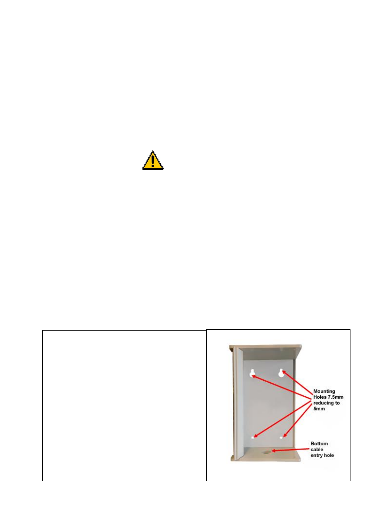
2.1 MECHANICAL INSTALLATION
The enclosure is provided with four 5mm
predrilled holes for mounting on a wall etc. It
is important that screws used for mounting the
enclosure should not be tightened excessively
thus damaging the enclosure.
The hole positions are shown in Figure 1.
Access to the inside of the enclosure is
gained by removing the 2 screws at the top
and bottom, carefully opening the hinged
front.
Protect the exposed printed circuit board
components during installation.
Figure 1. Inside the Case

TQ Environmental Limited
Issue 6: 01 June 2017
Page 8 of 12 8764UM6
Internal
Control Button
Connection
Function
1
RS485 ground
2 (Note a)
RS485 “A”
3
RS485 “B”
4
Power 0v
5(Note c)
Power +9 to +24 v DC
6
4 –20 mA, +ve
7
4 –20mA, -ve
8(Note b)
Connection for external buzzer (+ve)
9
Connection for external buzzer (-ve)
10 (Note b)
Volt free alarm contact (AL1)
11
Volt free alarm contact (AL1)
12
Volt free alarm contact (AL2)
13
Volt free alarm contact (AL2)
1
2
3
Connections 1 to 3
Figure 2. Electrical Connections
Connections 4 to 13
4
5
6
7
8
9
10
11
12
13
Table 2. Connection & Terminal Functions

TQ Environmental Limited
Issue 6: 01 June 2017
8764UM6 Page 9 of 12
PLEASE NOTE
2 CORE SCREENED CABLE SHOULD BE USED ON ALL
APPLICATIONS
Notes:-
“a”. The option of RS485 output is factory fitted Two core cable with overall
screen should be used for the RS485 connection
“b”. The buzzer and volt free alarm outputs are only available if factory fitted.
The buzzer should be rated according to the power supply used,
e.g. 12 or 24v dc.
“c” If the Unit has a 4-20 output then 24vdc is required
Figure 2 & Table 2 show the electrical connections.
Electrical cable entry to the enclosure should be through the predrilled hole at the
bottom of the enclosure.
The circuit in the PCB supplies a 4-20mA output signal, which is a current source
only. Total circuit load and cable resistance should be less than 600 Ohms for the
4-20mA loop and the unit should be powered from 24v dc for correct operation
After wiring the lid with sensor assembly should be closed and secured by the 2
screws ready for commissioning.

TQ Environmental Limited
Issue 6: 01 June 2017
Page 10 of 12 8764UM6
Figure 2:- Front Panel Functions
Auto-Span Initiated
CO2 Concentration Indicator
Auto-Zero Initiated
Concentration Alarm 1 Status
Concentration Alarm 1 Status
External Control Button
SECTION 3 –OPERATION
3.1 GENERAL
Please refer to Figure 2 for the position of LEDs and button.
The CO2concentration is displayed visually on the “CO2Concentration Indicator”. Lower
CO2concentrations are displayed by the green LEDs at the left of the display (marked “LO”)
and the higheston the red LEDs at the right of the display (marked “HI”. As the concentration
of CO2increases the number of LEDs illuminated will increase from left to right (8 in total).
All 8 LEDs will illuminate when the concentration reaches and exceeds the range of the
GD233.
The red LEDs marked “Concentration Alarm 1” and “Concentration Alarm 2” will
illuminate when the CO2concentration exceeds the set point value. At the same time the
alarm relays (if fitted) will actuate and the associated contacts for buzzer and alarms will
change state. The set points for the alarms and latch facility are factory set only.

TQ Environmental Limited
Issue 6: 01 June 2017
8764UM6 Page 11 of 12
3.2 STARTUP.
Ensure the voltage applied to the PCB is between 12 and 24Vdc.
On application of power, the LEDs associated with the “CO2Concentration Indicator” will
flash in sequence for a few seconds and the sensor will commence its warm up procedure.
This is indicated by the flashing of the green “Auto-Zero initiated” LED.
At the end of the warm up period (5minutes) the 4-20mA output and the “CO2
Concentration Indicator” will be “steady”.
The GD233 CO2Sensor will have been calibrated at the factory and will be ranged in
accordance with the application.
Both the“CO2Concentration Indicator” and 4-20mA output will have been set to this
range (0 - 5000ppm, 0 - 1% or 0 –2% CO2).
The 4-20mA is linear over the range of the instrument.
The zero point (0ppm CO2) will have been established in the factory using nitrogen or CO2
free air. In its intended application the GD233 CO2Sensor may have its zero point set
using air thus eliminating any offset due to the natural presence of CO2in the atmosphere.
Please refer to Auto-Zero Initiation below.
3.3 OPERATION.
3.3.1 Internal & External Control Buttons
These buttons may be used to initiate Auto-Zero, Auto-Span and cancel any latched
concentration alarms. The “Internal Control Button” (see Figure 2 for location) will
perform all the above functions. However, the “External Control Button” will only allow
any concentration alarms to be reset unless fully activated at the factory.
The functions of the Control Buttons are activated as follows:-
Press the appropriate control button. This will colour sequence the “CO2Concentration
Indicator”. The “CO2Concentration Indicator” will continue to sequence its colours
whilst the button remains pressed. Releasing the button when the appropriate sets of
coloured LEDs are illuminated will initiate the appropriate action.
The sequence of colours on the display is as follows:-
All LEDs on the “CO2Concentration Indicator” illuminated.
The GD233 CO2Sensor will return to normal operation, no action will have been initiated.
All 4 RED LEDs illuminated. This will cancel all latched concentration alarms.
NB, the alarms will immediately be reactivated if the CO2concentration is above its alarm
set point after cancellation.

TQ Environmental Limited
Issue 6: 01 June 2017
Page 12 of 12 8764UM6
All 3 GREEN LEDs illuminated. This will start the Auto Zero procedure. The green LED
marked “Z” will illuminate during this automatic procedure.
This will not operate if the “External Control Button” is pressed.
All 3 YELLOW LEDs illuminated. This will start the Auto Span –this procedure must only
be carried out by trained personnel.
This will not operate if the “External Control Button” is pressed.
3.3.2 Auto-Zero
This function will set the output to 0ppm CO2(0% CO2), 4.0 mA based upon the
concentration of CO2inside the enclosure. If a true zero-point at 0ppm CO2is required
instead of the CO2concentration inside the enclosure then nitrogen gas should be used to
fill the enclosure.
SECTION 4 - MAINTENANCE
4.1 ROUTINE MAINTENANCE.
The design of the sensor unit is such that no adjustment or calibration should be necessary
for extended periods of 2 years or longer. However, it is recommended that a system
function check is performed more frequently at 3 to 6 monthly intervals depending on the
application and local ambient conditions.
The sensor unit may require corrective maintenance if the output current is at a maximum
level, even if no combustible gas is present. Refer the unit to TQ Environmental PLC for
service.
If the unit ever becomes defective then it is necessary to refer the unit to a local TQ
representative or contact TQ directly. See the front cover of this manual for details on how
to contact TQ.
Please note there are no User Serviceable parts on the GD233 CO2Sensor.
4.2 WARRANTY
When the GD233 CO2Sensor is operated in accordance with conditions described in this
Manual the Standard Warranty is 12 months from the date of purchase of the instrument
from of TQ Environmental plc
SECTION 5 - SPARES
There are no spare parts associated with the GD233 CO2Sensor
TQ Environmental Limited, Silkwood Court, Wakefield, West Yorkshire, WF5 9TP. United Kingdom
Tel: +44 (0) 1924 271013 Email: [email protected]
Fax: +44 (0) 1924 264420 Web: www.tqenv.com
Table of contents
Other TQ Environmental Accessories manuals


Popular Accessories manuals by other brands


OLEI
OLEI LR-1BS3 user manual

Brüel & Kjaer Vibro
Brüel & Kjaer Vibro ds822 Series instructions

Asus
Asus ZenPower PD 10000 manual

ORION TELESCOPES & BINOCULARS
ORION TELESCOPES & BINOCULARS 8743 manual

ekwb
ekwb EK-FB KIT GA-X99 INSTALLATION AND MOUNTING MANUAL

Dini Argeo
Dini Argeo LTP Installation and operating instructions


