TQ Environmental GD133 User manual
TQ Environmental Ltd
Filename: 5832T4 Page 1 of 14
GD133 INFRARED
GAS SENSOR
OPERATING MANUAL
©TQ Environmental Ltd 2017
This manual must not be copied or reproduced in part without the express written
permission of TQ Environmental Ltd. All information contained herein is subject to
modification.
TQ Environmental Ltd, Silkwood Court, Wakefield, West Yorkshire, WF5 9TP
44 (0) 1924 271013 FAX 44 (0) 1924 264420
TQ ENVIRONMENTAL LTD BS EN ISO 9001

TQ Environmental Ltd
Filename: 5832T4 Page 2 of 14
CONTENTS:
Page no:
Proprietary 3
Warning, Cautions and Notes 3
Safety Warnings 4
Section 1 Description
1.1 General description 5
1.2 Method of detection 5
1.3 Sensor unit 5
1.4 Performance specifications 8
Section 2 Installation
2.1 Mechanical installation 9
2.2 Electrical installation 10
Section 3 Commissioning and Calibration
3.1 Commissioning 11
3.2 Calibration 11
3.3 Output current fault conditions 12
Section 4 Maintenance
4.1 Routine maintenance 13
4.2 Warranty 13
Section 5 Spares 14
Certification 15

TQ Environmental Ltd
Filename: 5832T4 Page 3 of 14
PROPRIETARY
No part of the hardware or documentation may be reproduced, transmitted,
transcribed, stored in a retrieval system, or translated into any language or computer
language, in any form or by any means, without prior written permission of TQ
Environmental LTD
While great efforts have been made to assure the accuracy and clarity of this document,
TQ Environmental LTD assumes no liability resulting from any omissions in this
document, or from misuse of the information obtained herein. The information in this
document has been carefully checked and is believed to be entirely reliable with all of
the necessary information included. TQ Environmental LTD reserves the right to make
changes to any products described herein to improve reliability, function, or design,
and reserves the right to revise this document and make changes from time to time in
content hereof with no obligation to notify any persons of revisions or changes. TQ
Environmental LTD does not assume any liability arising out of the application or any
use of any product or circuit described herein; neither does it convey license under its
patent rights or the rights of others.
WARNINGS, CAUTIONS AND NOTES
Warnings identify an operating or maintenance procedure, practice,
condition, or statement that, if not strictly followed, could result in
death or injury to personnel.
Cautions, which appear elsewhere in this manual, identify an
operating or maintenance procedure, practice, condition, or statement
that if not strictly followed could result in equipment damage or
serious impairment of system operation.
Notes highlight certain operating or maintenance conditions or
statements that are essential but not of known hazardous nature as
indicated by Warnings and Cautions.
Warnings, Cautions and Notes are included throughout this manual,
as required. Additionally, this section contains important Warnings
that may not be contained elsewhere within this instruction manual.

TQ Environmental Ltd
Filename: 5832T4 Page 4 of 14
SAFETY WARNINGS
THE GD133 INFRA RED GAS SENSOR SHOULD ONLY BE OPERATED
IN AN ENVIRONMENT WHICH IS NON-HAZARDOUS. THE GD133 IS
NOT CERTIFIED FOR USE IN ANY HAZARDOUS AREA.
FOR SAFETY REASONS, THE GD133 INFRA-RED GAS SENSOR MUST
BE INSTALLED, OPERATED AND SERVICED BY QUALIFIED
PERSONNEL ONLY. READ AND UNDERSTAND THIS INSTRUCTION
MANUAL COMPLETELY BEFORE OPERATING THE GD133 GAS
SENSOR.

TQ Environmental Ltd
Filename: 5832T4 Page 5 of 14
SECTION 1 - DESCRIPTION
1.1 GENERAL DESCRIPTION
The GD133 Infra-Red Gas Sensor is a highly reliable infra-red (IR) absorption type
sensor designed to give extended service under extreme conditions. The sensor is used
to detect the presence of infra-red active gases, eg carbon dioxide. In a typical
application, the sensor unit is electrically connected to a control system capable of
providing the power, accepting the 4-20mA signal generated and displaying the
concentration of the gas detected by the sensor . The control system may also
incorporate audible and/or visual alarms when the concentration reaches a
predetermined level. TQ control systems which meet these requirements include
models TQ800, TQ8000 and TQ8100.
The GD133 Sensor is used for diffusion sensing applications. These are applications
in which the sensor continuously monitors that part of the environment with which it is
in contact and the gas diffuses through the sensor’s optical path. This technical manual
covers the use of the GD133 Sensor as a diffusion type sensor.
1.2 METHOD OF DETECTION.
Detection of infra red active gases is accomplished by measuring the absorption of IR
energy by the gas being monitored. This measurement is made over a fixed distance
within a part of the sensor assembly called the Optical Bench. A miniature filament
lamp mounted, at one end of the optical bench, acts as an IR source. The lamp
illuminates an IR detector at the opposite end of the optical bench. The IR detector is
designed to detect IR energy only at the absorption wavelength. The introduction of an
infra red active gas into the optical path between the IR source and the IR detector
causes the detector output to reduce by an amount that can be calibrated for the gas
present. The filament lamp IR source is switched between two levels at a 1.5-second
rate, and is controlled by a precision circuit which provides high-stability operation and
reduces thermal drift. Through several stages, this signal is amplified to a 4-20mA
signal for local or remote indication.
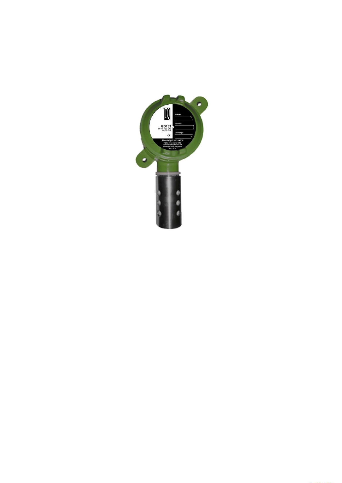
1.3 SENSOR UNIT DESCRIPTION. Refer to Figure 1.
The fully assembled GD133 Sensor unit has the approximate dimensions of 242mm
(Height) X 106mm (Width) X 92mm (Depth). The main components of the GD133
Sensor unit are:
Junction Box (J-Box) with Amplifier
Sensor Assembly
Guard

TQ Environmental Ltd
Filename: 5832T4 Page 6 of 14
220 APPROX
45
81.3
115
81.3
88 Approx
J-BOX WITH
AMPIFIER
INSIDE
STANDARD CONFIGURATION
SIDEVIEW
PLAN VIEW
M20 THREAD
M25 x 1.5mm
THREAD
WEATHER
PROTECTION
SHIELD
Figure 1 - Configuration
J-Box With Amplifier.
The junction box provides resistance to physical shock and gas-free protection to the
components mounted inside. The J-box contains a gasketed screw-on cover and
provision for a gland at the cable entry point (20mm conduit thread).
The amplifier printed circuit board (PCB) installed inside the J-Box, contains an
amplifier circuit for converting the IR detector’s absorption signals into a 4-20mA
output signal.
Sensor Assembly.
The sensor assembly consists of a Flame Arrestor surrounding an Optical Bench
Assembly. The entire Sensor Assembly is surrounded by a protective stainless steel
Guard. Refer to Figure 2.

TQ Environmental Ltd
Filename: 5832T4 Page 7 of 14
Flame Arrestor.
The Flame Arrestor is made of 316 Sintered Stainless Steel. The stainless steel ensures
high corrosion-resistance. The arrestor has a sheet of filter material fixed around the
outside to stop the entrance of dust, dirt and moisture.
Optical Bench Assembly.
The Optical Bench Assembly is concentrically enclosed within the Flame Arrestor and
the Guard.
Guard.
The stainless steel or resin moulded guard provides physical protection for the Flame
Arrestor and the Optical Bench Assembly. In sensor calibration operations, a
calibration cup can be installed over the Guard to provide for adequate flow of
calibration gas to the sensor.
Figure 2. - Sensor Assembly Location.

TQ Environmental Ltd
Filename: 5832T4 Page 8 of 14
1.4 PERFORMANCE SPECIFICATIONS.
Table 1. GD133 Sensor Performance Specifications.
FACTOR
SPECIFICATION
Detection Method:
IR Absorption
Sampling Method:
Continuous Diffusion
Measuring Range for CO2:
0 –2% volume. (The actual gas and range is displayed
on the label).
Accuracy:
+ 2% Full Scale (FS) Linearised
Repeatability:
+ 1% FS
Response Time:
1. Raw: <3 seconds to 90% of FS
2. Normal: <20 seconds to 90% of final reading (As
installed using 5% volume CO2test gas)
3. High Gas Levels: <5 seconds to FS Value
Temperature Range:
-20C to +50C
Humidity Range:
0 - 99% Relative Humidity (Non-condensing)
Mean Time Between Failures:
Electronics: 10 Years, IR Source: 7 Years
Warranty:
1 Year
Operating Voltage:
11 - 28Vdc
Operating Current:
135mA at 12 Vdc/75mA at 24 Vdc
Connections:
3 Wire, 4-20mA (Source)
Construction Materials:
Flame Arrestor: 316 Sintered Stainless Steel
Guard: 316 Stainless Steel
Weight:
1.05 kg (including junction box)
Electrical Hazardous Area
Certifications:
None

TQ Environmental Ltd
Filename: 5832T4 Page 9 of 14
SECTION 2 - INSTALLATION
2.1 MECHANICAL INSTALLATION.
2.1.1 GENERAL.
The GD133 Sensor is designed to be installed with the junction box and Flame Arrestor
Assembly with the Guard pointing downward. A typical installation for the GD133
Sensor is shown in Figure 3.
Figure 3. Sensor Unit Installation and Orientation.
2.1.2 INSTALLATION GUIDELINES.
To ensure continued reliable operation of the GD133 Sensor, the following installation
guidelines should be observed:
CAUTION
The calibration of the sensor may be affected by exposure to direct sunlight. If it is
necessary to install the sensor unit in a sunlit area, provide an adequate sunshade for
the sensor unit.
For the monitoring of heavier-than-air gases, mount the sensor unit as close as
practical to the floor or ground. For monitoring of lighter than air gases, install the
sensor unit as high as practical.
The sensor unit should be installed in a location where it is easily accessible for
repairs.
Mount the sensor unit in a position that minimises the risk of mechanical damage.
Prevent water and dust accumulation from affecting operation by mounting the
sensor unit with the guard pointing downward, as shown in Figure 3.

TQ Environmental Ltd
Filename: 5832T4 Page 10 of 14
It is important to ensure the conduit-entry point at the top of the J-Box is watertight.
Use an approved watertight packing gland. Apply commercial-grade pipe thread
sealant, such as Liquid Teflon, to the gland threads and install the appropriate
sealing washers.
When the GD133 is used in conjunction with a calibration cup for checking
operation the junction box must be mounted at least 10mm away from a vertical
surface.
The fixing holes on the junction box accept 5mm diameter bolts.
24VDC
0VDC
4-20mA Sig
Figure 4. Typical Electrical Installation Schematic.
2.2 ELECTRICAL INSTALLATION.
The amplifier circuit in the PCB supplies a 4-20mA output signal, which is a current
source only. An external common ground return must be provided, as shown in Figure
4. Total circuit load and cable resistance should be less than 600 Ohms for the 4-20mA
loop. The +24Vdc and common ground leads must be of sufficiently low resistance to
ensure the correct operating voltage at the PCB (refer to Table 1. for the operating
voltage range).
It is important that screened cable and cable glands are used with the instrument, and
that termination is carried out in the approved manner. The cable screen must NOT be
connected at the detector end, as it is to be connected to ground at the control panel.
See Appendix A for Electrical Connections with Alarm Relay Output.

TQ Environmental Ltd
Filename: 5832T4 Page 11 of 14
After wiring the lid of the junction box shall be screwed back onto the base.
CAUTION:- Ensure that the lid corresponding to its sensor is used when replacing lids
after installation or service.
SECTION 3 - COMMISSIONING & CALIBRATION
3.1 COMMISSIONING.
Prior to connecting power to the GD133 Sensor, the following preliminary checks
should be made.
a. Ensure the Sensor Assembly is screwed tightly into its junction box/enclosure.
b. Check that the Sensor Assembly is correctly wired to its PCB.
CAUTION
TO AVOID DAMAGE TO THE EQUIPMENT, ENSURE THE VOLTAGE
APPLIED TO THE PCB DOES NOT EXCEED 30 VOLTS.
c. Ensure the voltage applied to the PCB is between 12 and 28Vdc.
d. Inspect the unit for signs of damage or corrosion to the sensor assembly or its
junction box/enclosure.
After power has been applied, let the sensor unit function for 60 minutes prior to further
monitoring.
Please note that the current output from the GD133 will be 0.5mA for approximately
45 seconds after power has been applied.
3.2 CALIBRATION.
The GD133 is calibrated before it leaves the factory. The 4-20mA output will equate to
the gas and range requested by the Customer when the order is placed. The gas
monitored by the instrument and the range of the instrument are displayed on the label
on the enclosure cover.
It is likely that the GD133 Sensor will remain stable at its initial calibration settings for
long periods (typically 3 years) and on-site calibration is NOT required. Please refer to
4.1 (Routine Maintenance) for details of how to check the output from the sensor.

TQ Environmental Ltd
Filename: 5832T4 Page 12 of 14
3.3 OUTPUT CURRENT FAULT CONDITIONS.
The GD133 provides differing current output levels between 0mA and 4mA to
indicate various sensor fault conditions.
Indicated Current
Output
Description
0.5mA
Warm up after application of power to the unit until the
GD133 has completed its self-testing.
0.5mA
The optical bench (sensor head) output is too high.
1.0mA
The optical bench (sensor head) output is to low.
2.0mA
General optical bench fault or failure.
NOTE:
In the event of more than one fault occurring, the output currents for the
respective faults will be added together.

TQ Environmental Ltd
Filename: 5832T4 Page 13 of 14
SECTION 4 - MAINTENANCE
4.1 ROUTINE MAINTENANCE.
The design of the sensor unit is such that no calibration should be necessary for
extended periods of up to 3 years. However, it is recommended that a system calibration
check is performed more frequently at 3 to 6 monthly intervals depending on the
application and local ambient conditions. In this case, any small adjustment of the
output can be corrected on the control system receiving the signal from the GD133.
Please refer to the documentation associated with the control system for details on how
to carry out any adjustment which is necessary. TQ control systems which allow
adjustment of the incoming signal include models TQ800, TQ8000 and TQ8100.
The sensor unit may require corrective maintenance if any of the following occur:
Output current is at a maximum level, even if no infra red active gas is present.
Sensor response time is slower than noted in Table 1.
In each case refer the unit to TQ Environmental LTD for service.
CAUTION
THE OPTICAL BENCH AND THE SENSOR AMPLIFIER CIRCUITS ARE
MATCHED TO EACH OTHER AT THE FACTORY AND EITHER ONE
SHOULD NOT BE REPLACED AS A SINGLE UNIT. FOR THIS REASON
REPLACEMENT OF THE OPTICAL BENCH OR MAIN BOARD SHOULD
NOT BE ATTEMPTED IN THE FIELD. REFER THE UNIT TO TQ
ENVIRONMENTAL LTD FOR SERVICE.
If the unit ever becomes defective such that it is necessary to refer the unit to a service
facility, an exchange unit can be provided while the defective unit is being serviced at
the facility. Contact the local TQ representative or contact TQ directly. See the front
cover of this manual for details on how to contact TQ.
Please note there are no User Serviceable parts on the GD133.
4.2 WARRANTY
When the GD133 Infra-Red Gas Sensor is operated in accordance with conditions
described in this Manual the Standard Warranty is One Year from the date of purchase
of the instrument from of TQ Environmental LTD

TQ Environmental Ltd
Filename: 5832T4 Page 14 of 14
Table of contents
Other TQ Environmental Accessories manuals


Popular Accessories manuals by other brands


Axis
Axis 260A12 Installation and operating manual

Vertiv
Vertiv SmartRow DCR Installer/user guide

netvox
netvox Contact Sensor Series user manual

Jaypro Sports
Jaypro Sports RDC SERIES Assembly & instruction manual

Tecfluid
Tecfluid FLOMID Series instruction manual

PCB Piezotronics
PCB Piezotronics IMI SENSORS HT640B71 Installation and operating manual