TQ Environmental TQ131 User manual

INFRARED
REFRIGERANT GAS
SENSOR
OPERATING
MANUAL
TQ Environmental Limited
Silkwood Court
Wakefield
WF5 9TP
United Kingdom
Tel: +44 (0) 1924 271013
Fax: +44 (0) 1924 264420
Email: sales@tqenv.com
Web: www.tqenv.com
TQ131

Issue:8 March 2020 4951MMA8 Page 2 of 16
CONTENTS Page No
1 Description 5
1.1 General Description 5
1.2 Method of Detection 5
1.3 Sensor Unit Description 5
1.4 Gases Monitored 6
1.5 Models Covered by Manual 6
1.6 Performance Specification 7
2 Installation 8
2.1 Mechanical 8
2.1.1 General 8
2.1.2 Installation Guidelines 9
2.2 Electrical Installation 10
2.2.1 4 – 20 mA Version 10
2.2.2 Alarm Relay Version 10
3 Commissioning & Calibration 11
3.1 Commissioning 11
3.2 Calibration 11
3.3 Output Current Calculation 13
3.3.1 4 – 20 mA Version 13
4 Maintenance 14
4.1 Routine Maintenance 14
4.2 Warranty 14
5 Spares 14

Issue:8 March 2020 4951MMA8 page 3 of 16
PROPRIETARY
No part of the hardware or documentation may be reproduced, transmitted, transcribed, stored in a
retrieval system, or translated into any language or computer language, in any form or by any means,
without prior written permission of TQ Environmental Limited.
While great efforts have been made to assure the accuracy and clarity of this document,
TQ Environmental Limited assumes no liability resulting from any omissions in this document, or from
misuse of the information obtained herein. The information in this document has been carefully
checked and is believed to be entirely reliable with all of the necessary information included.
TQ Environmental Limited reserves the right to make changes to any products described herein to
improve reliability, function, or design, and reserves the right to revise this document and make
changes from time to time in content hereof with no obligation to notify any persons of revisions or
changes.
TQ Environmental Limited does not assume any liability arising out of the application or any use of
any product or circuit described herein; neither does it convey license under its patent rights or the
rights of others.
COPYRIGHT
© TQ Environmental Limited 2000-2015
This manual must not be copied or reproduced in part without the express written
permission of TQ Environmental Limited.
All information contained herein is subject to modification
WARNINGS, CAUTIONS AND NOTES
Warnings identify an operating or maintenance procedure, practice,
condition, or statement that, if not strictly followed, could result in death or injury to
personnel.
Cautions, which appear elsewhere in this manual, identify an operating or
maintenance procedure, practice, condition, or statement that if not strictly followed
could result in equipment damage or serious impairment of system operation.
Notes highlight certain operating or maintenance conditions or statements that are
essential but not of known hazardous nature as indicated by Warnings and Cautions.
Warnings, Cautions and Notes are included throughout this manual, as required.
Additionally, this section contains important Warnings that may not be contained
elsewhere within this instruction manual.

Issue:8 March 2020 4951MMA8 Page 4 of 16
SAFETY WARNINGS
THE GD131 FREON SENSOR MUST ONLY BE USED IN AREAS WHERE
POTENTIALLY FLAMMABLE GASES ARE NOT PRESENT.
FOR SAFETY REASONS, THE GD131 INFRA-RED GAS SENSOR MUST BE
INSTALLED, OPERATED AND SERVICED BY QUALIFIED PERSONNEL ONLY.
.
READ AND UNDERSTAND THIS INSTRUCTION MANUAL COMPLETELY
BEFORE OPERATING THE GD131 GAS SENSOR.

Issue:8 March 2020 4951MMA8 page 5 of 16
SECTION 1 - DESCRIPTION
1.1 GENERAL DESCRIPTION
The GD131 Infra-Red Sensor is a highly reliable infra-red (IR) absorption type sensor
designed to give extended service under extreme conditions. The sensor is used to detect
the presence of Refrigerant gases (R22, R134a, and similar gases). In a typical application,
the sensor unit is electrically connected to a system capable of either providing readouts
indicating the concentration of the gas detected by the sensor or generating alarms from
volt free alarm contacts changing over when a preset concentration of the refrigerant gas is
detected.
The GD131 Sensor is used for diffusion sensing applications. These are applications in
which the sensor continuously monitors that part of the environment with which it is in
contact and the gas diffuses through the sensor’s optical path. This technical manual covers
the use of the GD131 Sensor as a diffusion type sensor. As an alternative the sensor may
be equipped with “flow-through” measurement cell where an external pump is used to
introduce gas from a remote sensing point to the sensor as part of a sampling system.
1.2 METHOD OF DETECTION.
Detection of refrigerant gases is accomplished by measuring the absorption of IR energy
by the gas being monitored. This measurement is made over a fixed distance within a part
of the sensor assembly called the Optical Bench. A high intensity IR emitting lamp is
mounted, at one end of the optical bench. The lamp illuminates an IR detector at the
opposite end of the optical bench. The IR detector is designed to detect IR energy only
within a specific wavelength range at which adsorption of energy by the refrigerant gases
occurs. The introduction of the refrigerant gas into the optical path between the IR source
and the IR detector causes the detector output to reduce by an amount proportional the
refrigerant gas present. The IR source is switched between two levels at a 1.5-second rate,
and is controlled by a precision circuit which provides high-stability operation and reduces
thermal drift. Through several stages, this signal is amplified to a 4-20mA signal for remote
indication or to generate the concentration alarm.
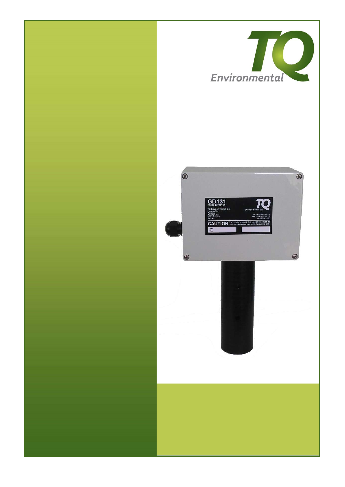
1.3 SENSOR UNIT DESCRIPTION.
The fully assembled GD131 Sensor unit has the approximate, overall dimensions of
285mm (Height) X 154mm (Width) X 80mm (Depth). The main components of the GD131
Sensor unit are:
Junction Box (J-Box) with Amplifier
Optical Bench Assembly
Guard
Filter

Issue:8 March 2020 4951MMA8 Page 6 of 16
J-Box With Amplifier.
The junction box provides resistance to physical shock and gas-free protection to the
components mounted inside. The J-box contains a cover and provision for both a cable
gland at the cable entry point (16mm conduit thread) and a separate earthing point.
The amplifier printed circuit board(s) (PCB) installed inside the J-Box, contains an amplifier
circuit for converting the IR detector’s absorption signals into a 4-20mA output signal and,
when required, relays to provide volt-free alarm contacts.
Optical Bench Assembly.
The Optical Bench Assembly is surrounded by a field changeable hydrophobic/particulate
filter to reduce the risk of moisture and solid particles entering the optical bench.
Guard.
The plastic guard provides mechanical protection for the optical bench and, on “diffusion”
versions, the filter. A calibration cup (not supplied) can be installed over the Guard to provide
an adequate flow of calibration gas to the sensor in sensor calibration operations on the
“diffusion” versions.
1.4 GASES MONITORED.
The GD131 Sensor is designed to monitor a broad spectrum of refrigerant gases including
ammonia and has been designed to allow the selection of alternative wavelengths to allow
monitoring of those IR active gases outside the normal wavelength band.
1.5 MODELS COVERED BY THIS MANUAL
TQ PART NUMBER
OPTION
OUTPUT
131
-
020
Diffusion Sensor
4
-
20mA
131
-
021
Flow Through Cell
4
-
20mA
131
-
022
Diffusion Sensor
Relay (Alarm)
131
-
023
Flow Through Cell
Relay (Alarm)

Issue:8 March 2020 4951MMA8 page 7 of 16
1.6 PERFORMANCE SPECIFICATIONS.
Table 1. GD131 Sensor Performance Specifications.
FACTOR SPECIFICATION
Detection Method: IR Absorption
Sampling Method: Continuous Diffusion
Measuring Range: 0 – 2000 ppm R134a. Other gases may have
different ranges. Higher ranges are available
Versions: 1) 4-20mA output (TQ P/N 131-020 & 131-021)
OR
2) 2 x “change-over” alarm contacts at factory set
concentrations (TQ P/N 131-022 or 131-023)
Accuracy: + 2% Full Scale Linearised
Repeatability: + 1% Full Scale
Response Time: T90 < 1min.
Temperature Range: -20C to +40C
Humidity Range: 0 - 99% Relative Humidity (Non-condensing)
Mean Time Between Failures: Electronics: 10 Years, IR Source: 3 Years
Warranty: 12 months
Operating Voltage: 24 Vdc (nominal)
Operating Current: 100 mA at 24 Vdc
Connections: 3 Wire, 4-20mA (Source) version, 5 or 8 wire alarm
version
Construction Materials: Epoxy painted LM25 junction box, 304 stainless
steel
Optical bench, plastic guard, hydrophobic filter
Weight: 1.25 kg (including junction box)
Electrical Hazardous Area
Certifications:
None. Non-hazardous area use only

Issue:8 March 2020 4951MMA8 Page 8 of 16
2 INSTALLATION
2.1 MECHANICAL INSTALLATION.
2.1.1 GENERAL.
The GD131 Sensor is designed to be installed with the optical bench pointing down (ie
below the junction box). Figure 1 shows the installation.
Mounting
Holes
Junction
Box
Mounting
Holes
Gas Entry
Points
(Diffusion
Version)
Optical
Bench
Guard Tube
Notes:
1) The instrument is to be mounted vertically,
2) The overall height (285mm) may vary depending upon the range of the instrument.
Figure 1. Sensor Unit Installation and Orientation.

Issue:8 March 2020 4951MMA8 page 9 of 16
2.1.2 INSTALLATION GUIDELINES.
To ensure continued reliable operation of the GD131 Sensor, the following installation
guidelines should be observed:
CAUTION
The calibration of the sensor may be affected by exposure to direct sunlight. If it is necessary
to install the sensor unit in a sunlit area, provide an adequate sunshade for the sensor unit.
The sensor unit should be installed in a location where it is easily accessible for repairs.
Mount the sensor unit in a position that minimises the risk of mechanical damage.
Prevent water and dust accumulation from affecting operation by mounting the sensor
unit with the sensor pointing downward, as shown in Figure 1.
It is important to ensure the conduit-entry point on the J-Box is watertight and that the
lid is firmly seated and secured.
The measurement cell is provided with gas inlet and outlet connectors on the “flow
through” version. The cell is not sensitive to direction of gas flow. An external coalescing
and / or particulate filter should be used to provide a clean and dry gas to the sensor.
The mounting holes on the junction box are 3.8mm wide, 143mm between centres
(horizontal) and 101mm between centres (vertical).
FB
-
+
FIELD TERMINAL
BLOCK ON PCB
CUSTOMERS EQUIPMENT
24V DC
0V DC
24V DC POWER SUPPLY
COMMON 0v
4-20mA AMPLIFIER
OUTPUT
24 V DC
Rload
Figure 2. Typical Electrical Installation Schematic (4-20mA Version).
FB
(4-20mA)
0v
+24v dc
Refer to Figure 5 for the location of the connector on the pcb.
Figure 3. Power & Output Connections on PCB (4-20mA Version).

Issue:8 March 2020 4951MMA8 Page 10 of 16
2.2 ELECTRICAL INSTALLATION.
2.2.1 4-20mA Version
The amplifier circuit in the PCB supplies a 4-20mA output signal, which is a current source
only. An external common ground return must be provided, as shown in Figure 2. Total
circuit load and cable resistance should be less than 600 Ohms for the 4-20mA loop. The
+24Vdc and common ground leads must be of sufficiently low resistance to ensure the
correct operating voltage at the PCB .
The connection points on the PCB are shown in Figure 3.
Please note that the Field Terminal Block will not be available on the Alarm Relay version.
2.2.2 Alarm Relay Version
Connections are made to the pcb in accordance with Figure 4.
The 2 concentration alarm set points are factory set according to the Customer’s instructions
and cannot be modified in the field.
34
56 7 8
12
CONNECTIONS
1. 0v
2. NO, Alarm 1
3. C, Alarm 1
4. NC, Alarm 1
5. 24v dc
6. NO, Alarm 2
7. C, Alarm 2
8. NC, Alarm 2
Figure 4. Power & Output Connections on PCB (Relay Version).
NO, C & NC refer to relay contacts Normally Open, Common and Normally Closed when
the relay is in the non-energised state, gas concentration below the appropriate set point.

Issue:8 March 2020 4951MMA8 page 11 of 16
3 COMMISSIONING & CALIBRATION
3.1 COMMISSIONING.
Prior to connecting power to the GD131 Sensor, the following preliminary checks
should be made.
a. Ensure the GD131 is securely mounted and inspect the unit for signs of damage or
corrosion to the sensor assembly or its junction box/enclosure.
CAUTION.
b. Ensure the voltage applied to the PCB is between 22 and 28Vdc.
c. After power has been applied, let the sensor unit function for 90 minutes prior to
further monitoring.
Please note that the current output from the GD131 will be 0.5mA for approximately 110
seconds after power has been applied.
d. Following an initial 90 minute warm up period, It may be
necessary to reset the baseline (zero) of the GD131 as described
in section 3.2 below.
3.2 CALIBRATION.
The GD131 sensor will remain stable for extended periods of time and on site calibration is
not required.
However, to preserve accuracy, the baseline (or zero) may require adjustment from time to
time. The baseline is that associated with a gas which does not contain any refrigerant gas,
eg use air or nitrogen. To adjust the baseline it will be necessary to either move the sensor
to an area known not to contain a refrigerant gas or introduce the appropriate gas from a
cylinder containing air or nitrogen. A cone may be used to cover the sensor head on
“diffusion sensors” providing a convenient way of introducing gas to the sensor whilst the
baseline is adjusted.
CAUTION.
THE CYLINDER MUST BE FITTED WITH A PRESSURE REGULATOR AND
FLOWMETER, THE COMBINATION CAPABLE OF SUPPLYING GAS AT A FLOW RATE
OF ABOUT 1 LITRE/MINUTE AT ATMOSPHERIC PRESSURE.

Issue:8 March 2020 4951MMA8 Page 12 of 16
Reset baseline using onboard pcb button.
Before starting the adjustment procedure it is necessary to remove the lid form the
enclosure (4 screws) and locate the calibration button on the main pcb.
See Figure 5
Power &
4-20mA Connector
Calibration
Button
Calibration
LED
Power
Indicator
PCB
Serial No
Figure 5. Button & Connector Locations
As an aid, a calibrated meter capable of measuring dc current in the range 0 – 25mA may
be connected to the field terminals on the pcb in place of the mA loop. It will be necessary
to remove power whilst this is carried out. Please leave the GD131 for at least 10mins after
power has been reconnected before adjusting the baseline.
Introduce the baseline gas or clean air and allow the output to stabilise. Press and keep
pressed the Calibration button for between 5 and 7 seconds noting that the adjacent
led illuminates whilst the button is pressed. When the button is released and has been
pressed for the required period, the led will flash for a period of about 1minute whilst the
baseline is adjusted to 4.0mA, resetting the zero output. IT IS ESSENTIAL THAT CLEAN
AIR OR GAS CONTAINING NO REFRIGERANT IS FLOWING IN AND AROUND THE
SENSOR THROUGHOUT THIS PERIOD. Repeat this procedure if the LED does not start
to flash when the button is released after about 6 sec.
If a meter has been attached the progress of the procedure may be monitored, the output
will decrease to 1.5mA for a 5 second period at the beginning and end of the procedure,
whilst a slower progress towards 4.0mA will be observed during the middle part of the
procedure.
At the end of the procedure the supply of gas may be halted, the meter removed and the
output wires reconnected.
Do not forget to replace the lid on the enclosure before putting the GD131 back into
service.

Issue:8 March 2020 4951MMA8 page 13 of 16
Reset baseline using Calibration Magnet.
On some sensors, the pcb reset button is not fitter. These sensors have a “Red Dot”
calibration mark on the case. See Figure 6 and can be adjusted using the supplied
calibration magnet.
Figure 6. Calibration using a Magnet
The procedure is exactly the same as if using the onboard pcb button. But instead
of pressing the button for 5 - 7 seconds. Hold a calibration magnet to the mark shown
above, also for 5 - 7 seconds, then remove. The procedure can be done without
removing the cover but it may be easier with the cover removed, then the calibration
LED can be seen to flash if the magnet has been applied for the correct length of
time before removal .
3.3 OUTPUT CURRENT CALCULATION.
3.3.1 4-20mA Version
This version of the GD131 Sensor is designed to provide a 4-20mA output equivalent to the
range of the sensor, eg 0 to 2000ppm R134a. The concentration of gas may be calculated
using the following relationship:-
Gas Concentration
(ppm) =
(mA
–
4)
X GD131 Range
(ppm)
16

Issue:8 March 2020 4951MMA8 Page 14 of 16
4 MAINTENANCE
4.1 ROUTINE MAINTENANCE.
The design of the sensor unit is such that no calibration should be necessary for extended
periods of up to 2 years. However, it is recommended that a baseline adjustment as
described in section 3.2 system is performed on a more frequent basis to preserve accuracy
depending on the application and local ambient conditions.
The sensor unit may require corrective maintenance if any of the following occur:
Output current is at a maximum level, even if no infra red active gas is present,
The sensor output indicates a fault condition (<4mA), or
The sensor does not respond to the gas.
In each case refer the unit to TQ Environmental Limited for service.
CAUTION
THE OPTICAL BENCH AND THE SENSOR AMPLIFIER CIRCUITS ARE MATCHED TO
EACH OTHER AT THE FACTORY AND NEITHER SHOULD BE REPLACED AS A
SINGLE UNIT. FOR THIS REASON REPLACEMENT OF THE OPTICAL BENCH OR
MAIN BOARD SHOULD NOT BE ATTEMPTED IN THE FIELD. REFER THE UNIT TO
TQ ENVIRONMENTAL PLC FOR SERVICE.
On the diffusion version, the filter may be replaced as follows:-
Remove the two M3 grub screws located towards the base of the sensor.
Unscrew the guard from junction box releasing the filter.
Replace the filter and re-assemble in the reverse order. The procedure above is dependent
upon the range of the GD131. If in doubt please consult TQ.
NB The filter should be replaced by TQ personnel as damage caused to the instrument will
invalidate the warranty.
Please note there are no other User Serviceable parts on the GD131.
4.2 WARRANTY
When the GD131 Infra-Red Gas Sensor is operated in accordance with conditions
described in this Manual the Warranty is one (1) year from the date of purchase of the
instrument from TQ Environmental Limited.
5 SPARES
Description TQ Part No:
Filter 317-032

Issue:8 March 2020 4951MMA8 page 15 of 16

Issue:8 March 2020 4951MMA8 Page 16 of 16
TQ Environmental Limited, Silkwood Court, Wakefield, West Yorkshire, WF5 9TP. United Kingdom
Tel: +44 (0) 1924 271013 Email: [email protected]
Fax: +44 (0) 1924 264420 Web: www.tqenv.com
Table of contents
Other TQ Environmental Accessories manuals