TQ KTX2-F User manual

TO Av¡at¡on
EASA.AP445
KTX2-F.01 00
MAN
KTX2-F.0001
MAN
Operation and lnstallation Manual
Doc.-No.
lssue:
ECR-No.
Date:
MoC:
KTX2-F.A-MAN
0001
KTX2.F.A-ECR.O204
2019-07-03
0
Document Release
lFunction Name Ðate Signature
Prepared by
Checked by
Thomas Wähner
Florian Holzner
2019-07-03 /,
2019-07-03 iV w,1,,-
áz
Approved by Thomas Eilers 2019-07-03
KTX2-F.A-MAN.0001.docx Page 1 of74
@ TQ-Systems GmÞH. All ¡nformat¡on contained ¡n th¡s documents have to be treated strictly conf¡dential. The transfer of presentations and know-how to third parties
requ¡res the pr¡or wr¡tlen consent of TQ-Systems GmbH.

TQ Aviation KTX2-F.0100
EASA.AP445 MAN
KTX2-F.A-MAN.0001.docx Page 2 of 74
© TQ-Systems GmbH. All information contained in this documents have to be treated strictly confidential. The transfer of presentations and know-how to third parties
requires the prior written consent of TQ-Systems GmbH.

TQ Aviation KTX2-F.0100
EASA.AP445 MAN
KTX2-F.A-MAN.0001.docx Page 3 of 74
© TQ-Systems GmbH. All information contained in this documents have to be treated strictly confidential. The transfer of presentations and know-how to third parties
requires the prior written consent of TQ-Systems GmbH.
KTX2-F
Mode-S Transponder
Flat (160mm) format
KTX2-F (flat 160mm format) with ADS-B with Part-No 295153
Operation and Installation
Manual

TQ Aviation KTX2-F.0100
EASA.AP445 MAN
KTX2-F.A-MAN.0001.docx Page 4 of 74
© TQ-Systems GmbH. All information contained in this documents have to be treated strictly confidential. The transfer of presentations and know-how to third parties
requires the prior written consent of TQ-Systems GmbH.
Revision List
Revision Date Topic
0100 2019-02-07 Initial Release
Service Bulletins (SB)
Service Bulletins must be inserted in the manual and added to this table.
No SB No Rev. Release date Date Added Name

TQ Aviation KTX2-F.0100
EASA.AP445 MAN
KTX2-F.A-MAN.0001.docx Page 5 of 74
© TQ-Systems GmbH. All information contained in this documents have to be treated strictly confidential. The transfer of presentations and know-how to third parties
requires the prior written consent of TQ-Systems GmbH.
Change History
Product
Revision Date Description of Change

TQ Aviation KTX2-F.0100
EASA.AP445 MAN
KTX2-F.A-MAN.0001.docx Page 6 of 74
© TQ-Systems GmbH. All information contained in this documents have to be treated strictly confidential. The transfer of presentations and know-how to third parties
requires the prior written consent of TQ-Systems GmbH.
Table of Contents
1. General ..................................................................................................................................... 9
1.1 Purpose............................................................................................................................. 9
1.2 Scope ................................................................................................................................ 9
1.3 Terminology....................................................................................................................... 9
1.4 Symbols ............................................................................................................................ 9
1.5 Abbreviations................................................................................................................... 10
1.6 Customer Support ........................................................................................................... 14
1.7 Features .......................................................................................................................... 15
1.8 Safety-Conscious Utilization ............................................................................................ 16
1.9 Restriction for Use........................................................................................................... 16
2. Operation ................................................................................................................................ 17
2.1 Controls and Display ....................................................................................................... 17
2.1.1 Controls....................................................................................................................... 18
2.1.2 Display Indications....................................................................................................... 19
2.2 Normal Operation Menu Structure ................................................................................... 20
2.2.1 ON/OFF Switching....................................................................................................... 21
2.2.2 Transponder-Modes .................................................................................................... 22
2.2.3 Squawk Code Change................................................................................................. 23
2.2.4 VFR – Squawk............................................................................................................. 24
2.2.5 Squawk Ident (ID, SPI) ................................................................................................ 25
2.2.6 Airborne/Ground Indication.......................................................................................... 25
2.2.7 ADS-B Status Indication .............................................................................................. 27
2.2.8 Adjustable parameters in normal operation mode........................................................ 28
2.2.9 GNSS Data.................................................................................................................. 30
3. Setup Mode............................................................................................................................. 31
3.1 Controls and Display ....................................................................................................... 31
3.2 Entering Set Up ............................................................................................................... 33
3.3 Controls........................................................................................................................... 33
3.3.1 Selection...................................................................................................................... 33
3.3.2 Return to parent menu................................................................................................. 33
3.3.3 Cancel/Discard ............................................................................................................ 33
3.4 Setup Menus ................................................................................................................... 34
3.4.1 Brightness ................................................................................................................... 34
3.4.2 Flight-Identifier (Flight ID) ............................................................................................ 37
3.4.3 Modify VFR.................................................................................................................. 47
3.4.4 Factory Reset .............................................................................................................. 49
3.4.5 Test Menu ................................................................................................................... 49
4. Errors, Warnings and Notifications .......................................................................................... 53
4.1 Degrading failures ........................................................................................................... 53
4.1.1 Low Battery Voltage..................................................................................................... 54
4.1.2 Very Low Battery Voltage ............................................................................................ 55
4.2 Limiting failures ............................................................................................................... 56
4.3 Severe failures ................................................................................................................ 56
4.4 Notifications..................................................................................................................... 58
4.4.1 GNSS Data CRC Failure ............................................................................................. 58
4.4.2 Do System Restart....................................................................................................... 58
5. Installation............................................................................................................................... 59
5.1 Equipment Connections................................................................................................... 59
5.1.1 Electrical Connections ................................................................................................. 59
5.1.2 Mutual Suppression..................................................................................................... 59
5.1.3 Ground Switch ............................................................................................................. 59

TQ Aviation KTX2-F.0100
EASA.AP445 MAN
KTX2-F.A-MAN.0001.docx Page 7 of 74
© TQ-Systems GmbH. All information contained in this documents have to be treated strictly confidential. The transfer of presentations and know-how to third parties
requires the prior written consent of TQ-Systems GmbH.
5.1.4 Static Air Port............................................................................................................... 60
5.1.5 GNSS Interface ........................................................................................................... 60
5.1.6 Antenna Connector...................................................................................................... 60
5.2 Wiring.............................................................................................................................. 64
5.2.1 Conductor Cross Section............................................................................................. 64
5.2.2 Wiring Scheme ............................................................................................................ 64
6. Drawings ................................................................................................................................. 65
7. Technical Data ........................................................................................................................ 67
7.1 General ........................................................................................................................... 67
7.2 Transmitter – Receiver .................................................................................................... 69
8. FCC related issues.................................................................................................................. 70
8.1 Radiofrequency radiation exposure Information:.............................................................. 70
8.2 Compliance ..................................................................................................................... 70
8.3 Modifications ................................................................................................................... 70
9. Maintenance ........................................................................................................................... 71
9.1 Periodic Maintenance ...................................................................................................... 71
9.2 Repair.............................................................................................................................. 71
9.3 Cleaning .......................................................................................................................... 71
10. EXCLUSIVE LIMITED WARRANTY and LIMITATIONS ON LIABILITY............................... 72
11. Software License Conformity............................................................................................... 73
List of Tables
Table 1: Transponder Modes ................................................................................................................. 22
Table 2: GND Switch Support ................................................................................................................ 40
Table 3: Certitified GNSS Units.............................................................................................................. 42
Table 4: Approved GNSS Units.............................................................................................................. 42
Table 5: List of supported GNSS Devices .............................................................................................. 43
Table 6: Degrading Failures................................................................................................................... 54
Table 7: Severe Failures........................................................................................................................ 57
Table 8: L-Band Antennas ..................................................................................................................... 61
Table 9: Common Antenna Cables ........................................................................................................ 62
Table 10: Technical Data ....................................................................................................................... 68
Table 11: Transmitter Data .................................................................................................................... 69
Table 12: Receiver Data ........................................................................................................................ 69
Table 13: General Data.......................................................................................................................... 69
List of Figures
Figure 1: Display Diagram...................................................................................................................... 17
Figure 2: Controls .................................................................................................................................. 18
Figure 3: Indicators ................................................................................................................................ 19
Figure 4: Operational menu structure..................................................................................................... 20
Figure 5: Initial Display........................................................................................................................... 21
Figure 6: Normal Operation.................................................................................................................... 22
Figure 7: VFR-Squawk........................................................................................................................... 24
Figure 8: Squawk Ident .......................................................................................................................... 25
Figure 9: Airborne/Ground Indication "FLY" ........................................................................................... 26
Figure 10: Airborne/Ground Indication "GND" ........................................................................................ 26
Figure 11: ADS-B Indication................................................................................................................... 27
Figure 12: Change Flight ID ................................................................................................................... 28
Figure 13: Change Brightness................................................................................................................ 28
Figure 14: GNSS Data Display............................................................................................................... 30
Figure 15: Button functions in Setup Mode............................................................................................. 31

TQ Aviation KTX2-F.0100
EASA.AP445 MAN
KTX2-F.A-MAN.0001.docx Page 8 of 74
© TQ-Systems GmbH. All information contained in this documents have to be treated strictly confidential. The transfer of presentations and know-how to third parties
requires the prior written consent of TQ-Systems GmbH.
Figure 16: Setup mode menu structure.................................................................................................. 32
Figure 17: Setup Menu 1........................................................................................................................ 33
Figure 18: Setup Menu 2........................................................................................................................ 33
Figure 19: Setup Brightness Menu......................................................................................................... 34
Figure 20: Button Illumination Mode "Off"............................................................................................... 35
Figure 21: Button Illumination Mode "On"............................................................................................... 35
Figure 22: Button Illumination Mode "Auto"............................................................................................ 36
Figure 23: Flight ID configuration ........................................................................................................... 37
Figure 24: FID Limitation Notification ..................................................................................................... 37
Figure 25: Flight ID Edit Menu................................................................................................................ 38
Figure 26: Device Parameter Configuration Menu.................................................................................. 39
Figure 27: Aircraft Category Selection Menu.......................................................................................... 40
Figure 28: Ground Switch Setup Menu .................................................................................................. 40
Figure 29: Maximum Speed Category Selection Menu........................................................................... 41
Figure 30: GNSS Device Selection Menu .............................................................................................. 42
Figure 31: Baud Rate Selection Menu.................................................................................................... 43
Figure 32: Aircraft Length/Width Configuration Menu............................................................................. 44
Figure 33: GNSS Antenna Offset Configuration Menu ........................................................................... 45
Figure 34: Delete Flight ID Menu ........................................................................................................... 46
Figure 35: Multiple Flight ID Selection Menu.......................................................................................... 47
Figure 36: Modify VFR Code Menu........................................................................................................ 47
Figure 37: Factory Reset Menu.............................................................................................................. 49
Figure 38: Test Menu............................................................................................................................. 49
Figure 39: Altitude Offset Calibration Menu............................................................................................ 50
Figure 40: Test Mode Menu ................................................................................................................... 51
Figure 41: Device Info Menu .................................................................................................................. 52
Figure 42: Low Battery Voltage.............................................................................................................. 54
Figure 43: Very Low Battery Voltage...................................................................................................... 55
Figure 44: Missing AA-Code .................................................................................................................. 56
Figure 45: Critical Error (Example)......................................................................................................... 56
Figure 46: GNSS CRC Failure ............................................................................................................... 58
Figure 47: System Restart ..................................................................................................................... 58
Figure 48: Wiring.................................................................................................................................... 64
Figure 49: Dimensions of KTX2-F Standard round format...................................................................... 65
Figure 50: Panel Cut-Out ....................................................................................................................... 66

TQ Aviation KTX2-F.0100
EASA.AP445 MAN
KTX2-F.A-MAN.0001.docx Page 9 of 74
© TQ-Systems GmbH. All information contained in this documents have to be treated strictly confidential. The transfer of presentations and know-how to third parties
requires the prior written consent of TQ-Systems GmbH.
1. General
1.1 Purpose
This manual contains information about the physical, mechanical and electrical characteristics,
installation and operation for the KTX2-F Mode S Transponder. Additionally it describes the ADS-B
functionality for a compliant ADS-B Out installation using Extended Squitter (ES).
1.2 Scope
This manual applies to the operation and installation of the KTX2-F Mode S Transponder.
At the publication date of this manual the software version is 0100 and the FPGA version is 0042. The
software and FPGA versions are subject to change without further notice.
1.3 Terminology
Except where specifically noted, references made to “the Unit” or “the Installation” will apply to the
transponder defined in 1.2.
Referenced Documents where the respective document is identified by document number, document
title and issue.
•
The word MUST in the text denotes a mandatory instruction. A deviation is not permissible.
•
The word SHOULD in the text denotes a recommendation or advice. Such recommendations or
advice is expected to be followed unless good reasons are stated for not doing so.
•
The word MAY in the text denotes a permissible practice or action.
Note: Background information contained in this document is always indicated by using an italic character
font.
1.4 Symbols
DANGER:
Advices whose non-observance can cause radiation damage to the
human body or ignition of combustible materials.
ATTENTION:
Advices whose non-observance can cause damage to the device or
other parts of the equipment or reduce the correct functionality of the
device.
INFORMATION:
Supplemental information for operating the device.

TQ Aviation KTX2-F.0100
EASA.AP445 MAN
KTX2-F.A-MAN.0001.docx Page 10 of 74
© TQ-Systems GmbH. All information contained in this documents have to be treated strictly confidential. The transfer of presentations and know-how to third parties
requires the prior written consent of TQ-Systems GmbH.
1.5 Abbreviations
Abbr.
Meaning
Explanation
AA
Aircraft Address
Assigned ICAO 24 bit address
AC
Advisory Circular
Information and guidance publication
ADC
Analog Digital
Converter
ADF
Automatic Direction
Finder
Navigation equipment
ADS
-B
Automatic
Dependent
Surveillance
Broadcast
ALT
Altitude
The transponder will respond to all interrogations and transmits
ABS
-B messages.
ATC
Air Traffic Control
ATCRBS
Air Traffic Control
Radar Beacon
System
BAT Battery
BNC Bayonet Neill-
Concelman
A RF connector type.
CFR Code of Federal
Regulations
COMM Communication(s)
CRC
Cyclical Redundancy
Check(s)
DME Distance Measuring
Equipment
EASA European Aviation
Safety Agency
ECR Engineering Change
Request
EEPROM Electrically Erasable
Programmable
Read-Only Memory

TQ Aviation KTX2-F.0100
EASA.AP445 MAN
KTX2-F.A-MAN.0001.docx Page 11 of 74
© TQ-Systems GmbH. All information contained in this documents have to be treated strictly confidential. The transfer of presentations and know-how to third parties
requires the prior written consent of TQ-Systems GmbH.
Abbr.
Meaning
Explanation
ENV Environment
ES Extended Squitter
ETSO European Technical
Standard Order
FAA Federal Aviation
Administration
FAX Facsimile
FCC Federal
Communications
Commission
FID Flight ID Number of flight plan if assigned, else Registration number of
aircraft
FLY Flight The aircraft is in “Flight Mode”
FPGA Field-Programmable
Gate Array
GND Ground The transponder will respond to Mode S ground interrogations
from surface movement radar.
ABS
-B messages are transmitted (Surface messages).
GNSS Global Navigation
Satellite System
GPS Global Positioning
System
ICAO International Civil
Aviation
Organization
IDT Identify
LSA Light Sport Aircraft
MAN Manual
MCU Microcontroller Unit
MIL Military
MTL Minimum Triggering
Level

TQ Aviation KTX2-F.0100
EASA.AP445 MAN
KTX2-F.A-MAN.0001.docx Page 12 of 74
© TQ-Systems GmbH. All information contained in this documents have to be treated strictly confidential. The transfer of presentations and know-how to third parties
requires the prior written consent of TQ-Systems GmbH.
Abbr.
Meaning
Explanation
NMEA National Marine
Electronics
Association
ON Transponder Mode
“On”
The transponder will respond to all interrogations, but altitude
reporting is suppressed.
ABS
-B messages are transmitted.
RMC Recommended
Minimum Sentence
C
NMEA sentence
RSS Radio Standards
Specifications
(Canada)
RTCA Radio Technical
Commission for
Aeronautics
SAE Society of
Automotive
Engineers
SMA Sub-Miniature A
Connector
SPI Special Position
Identification (ID)
If activated on request by air traffic controller („Squawk Ident“) a
SPI Pulse is transmitted for 18 seconds. This highlights the
respective traffic item on the radar screen of the air traffic
controller.
STBY Standby The transponder is on, but will not reply to any interrogations or
transmit any ADS-B out messages.
SUB Subminiature
SUPP Suppression
TNC Threaded Neill-
Concelman
A RF connector type.
TSO Technical Standard
Order[
USA United States of
America
VFR
Visual Flight Rules

TQ Aviation KTX2-F.0100
EASA.AP445 MAN
KTX2-F.A-MAN.0001.docx Page 13 of 74
© TQ-Systems GmbH. All information contained in this documents have to be treated strictly confidential. The transfer of presentations and know-how to third parties
requires the prior written consent of TQ-Systems GmbH.
Abbr.
Meaning
Explanation
VSWR
Voltage Standing
Wave Ratio
WAAS Wide Area
Augmentation
System (GPS)
TQ Aviation KTX2-F.0100
EASA.AP445 MAN
KTX2-F.A-MAN.0001.docx Page 14 of 74
© TQ-Systems GmbH. All information contained in this documents have to be treated strictly confidential. The transfer of presentations and know-how to third parties
requires the prior written consent of TQ-Systems GmbH.
1.6 Customer Support
In order to facilitate a rapid handling of returned shipments, please send your request to the
email address below. Additional information and FAX number can be found on the TQ
Avionics web portal:
https://www.tq-avionics.com/
Any suggestions for improvement
of our
manuals are
welcome. Contact: info@tq-avionics.com
Information on software updates are available at TQ.
https://www.tq-avionics.com/

TQ Aviation KTX2-F.0100
EASA.AP445 MAN
KTX2-F.A-MAN.0001.docx Page 15 of 74
© TQ-Systems GmbH. All information contained in this documents have to be treated strictly confidential. The transfer of presentations and know-how to third parties
requires the prior written consent of TQ-Systems GmbH.
1.7 Features
In order to operate the Mode-S transponder it is necessary to
request an ICAO 24-Bit Aircraft Address at the responsible
National Aviation Authorities. The received code must be
configured within the transponder (see chapter 3.4.2.1.2).
•Class 1 Level 2els Non-Diversity Mode-S-Transponder for ground based
interrogations at 1030 MHz and response at 1090 MHz
•Replies to Secondary Radar Interrogations
oMode-A replies with a Squawk (one of 4096 possible Codes; e.g. flight plan
number, Squawk assigned by a Controller or the VFR Squawk).
oMode C replies, including encoded Flight Level.
oMode S replies, including Aircraft Address and Flight Level.
oIDENT capability for activating the “Special Position Identification“- Pulse
(SPI) for 18 seconds, which is requested by the Controller “Squawk Ident”
•ADS-B out:
oAirborne Position
oIdentification and Category
oAirborne Velocity
oOperational Status
oExtended Squitter Aircraft Status
•Maximum flight level 30 000ft; maximum airspeed 250kt
•Display information contains Squawk code, mode of operation and pressure
altitude
•
Temperature compensated
high
precision
piezo-resistive pressure sensor
•RS-232 data port enabling connection with mutual suppression and On the Ground
(weight on wheels) inputs. In addition, an appropriate GNSS receiver for ADS-B
can be connected
•8 storable entries for AA-/Aircraft-Code, FID
•
Ground-Switch support

TQ Aviation KTX2-F.0100
EASA.AP445 MAN
KTX2-F.A-MAN.0001.docx Page 16 of 74
© TQ-Systems GmbH. All information contained in this documents have to be treated strictly confidential. The transfer of presentations and know-how to third parties
requires the prior written consent of TQ-Systems GmbH.
1.8 Safety-Conscious Utilization
For safe operation of the transponder the following notices have to be observed:
•The installation of the transponder into an aircraft should be carried out only by an authorized
installation company. The country regulations always have to be observed.
•Use the transponder only within the specified conditions, see chapter 7.
Power supply:
• Do not connect the transponder to AC sources.
• Make sure that the transponder is connected to the mandatory DC source, see chapter 7.
• Do not connect the transponder with reversed polarity to the DC source.
Circuit breaker:
• The transponder should be protected from the aircraft power supply by a dedicated 3 A circuit
breaker or fuse (slow-blow).
Excessive pulses on the DC bus of the aircraft may cause damage on electrical circuits of any installed
instrument.
Do not switch ON the transponder during engine start or shutdown.
1.9 Restriction for Use
The transponder is to be used only inside the declared limits.

TQ Aviation KTX2-F.0100
EASA.AP445 MAN
KTX2-F.A-MAN.0001.docx Page 17 of 74
© TQ-Systems GmbH. All information contained in this documents have to be treated strictly confidential. The transfer of presentations and know-how to third parties
requires the prior written consent of TQ-Systems GmbH.
2. Operation
2.1 Controls and Display
Figure 1: Display Diagram

TQ Aviation KTX2-F.0100
EASA.AP445 MAN
KTX2-F.A-MAN.0001.docx Page 18 of 74
© TQ-Systems GmbH. All information contained in this documents have to be treated strictly confidential. The transfer of presentations and know-how to third parties
requires the prior written consent of TQ-Systems GmbH.
2.1.1 Controls
This chapter describes the use of the buttons and knobs during normal operation.
The usage while in setup mode is described in chapter 3.3.
Button Designation Function
ON/OFF Press to switch the transponder on and off. This switch is
mechanically locked until it is pressed a second time
VFR
1. Activate/deactivate VFR Squawk
2. Pressing the button for more than 3 seconds will show the
Brightness menu (see 2.2.8.2)
CHANGE
1. Exchange of the active and standby-Squawk
2. Pressing the button for more than 3 seconds will show the
GNSS data menu (see 2.2.9)
IDENT
1. „Squawk Ident“, a SPI Pulse is transmitted for 18 seconds
(in normal mode).
2. Pressing the button for more than 3 seconds will show the
Flight-ID menu (see 2.2.8.1)
MODE
1. Select Transponder-Mode STBY, GND, ON or ALT.
2. Pressing the button for more than 3 seconds will toggle the
ADS-B mode (On/Off)
Rotary knob
1. Enter a new Squawk (see 2.2.2)
2. Enter values and select options in submenus (see 3.3)
3. Confirm Warnings and Notifications
Figure 2: Controls
TQ Aviation KTX2-F.0100
EASA.AP445 MAN
KTX2-F.A-MAN.0001.docx Page 19 of 74
© TQ-Systems GmbH. All information contained in this documents have to be treated strictly confidential. The transfer of presentations and know-how to third parties
requires the prior written consent of TQ-Systems GmbH.
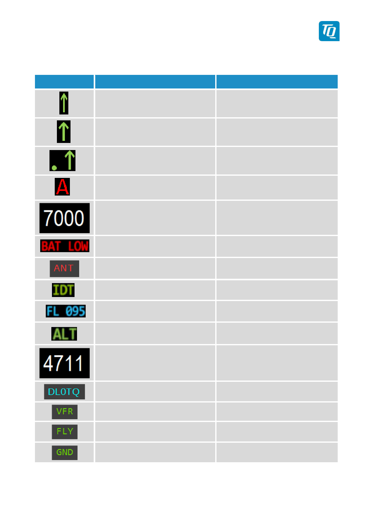
2.1.2 Display Indications
Indication Meaning Remark
Transponder is transmitting
Mode-A/C
Replies on
Interrogations
Appears per reply and persists for
some time
Transponder is transmitting
Mode-S
Replies on
Interrogations
Appears per reply and persists for
some time
Transponder is locked by a
ground station and will be
directly addressed
Appears at every addressed reply and
persists for some time
ADS-B out Status Status of ADS-B transmission
Active Squawk Is shown at upper position
Battery power too low Appears above Standby-Squawk
Failure indication See 4
IDENT- Marking is transmitted ID („Squawk Ident“) has been pressed
– active for 18s
Current Flight Level Flight Level (in 100ft steps)
Mode display
(STBY, ON, GND, ALT)
see chapter. 2.1.6 Transponder-
Modes
Standby-Squawk
Is shown at lower position.
Can be ex
changed with active Squawk
by pressing the UP/DOWN (“Change”)
button
Flight ID Only shown if a Flight ID is configured
with a valid Aircraft Address
VFR indication Shown while VFR squawk is used
Transponder is in airborne mode Only shown if Ground Switch support
is configured.
Transponder is in ground mode Only shown if Ground Switch support
is configured.
Figure 3: Indicators

TQ Aviation KTX2-F.0100
EASA.AP445 MAN
KTX2-F.A-MAN.0001.docx Page 20 of 74
© TQ-Systems GmbH. All information contained in this documents have to be treated strictly confidential. The transfer of presentations and know-how to third parties
requires the prior written consent of TQ-Systems GmbH.
2.2
Normal Operation
Menu Structure
Figure 4: Operational menu structure
This manual suits for next models
2
Table of contents
Other TQ Marine Radio manuals


