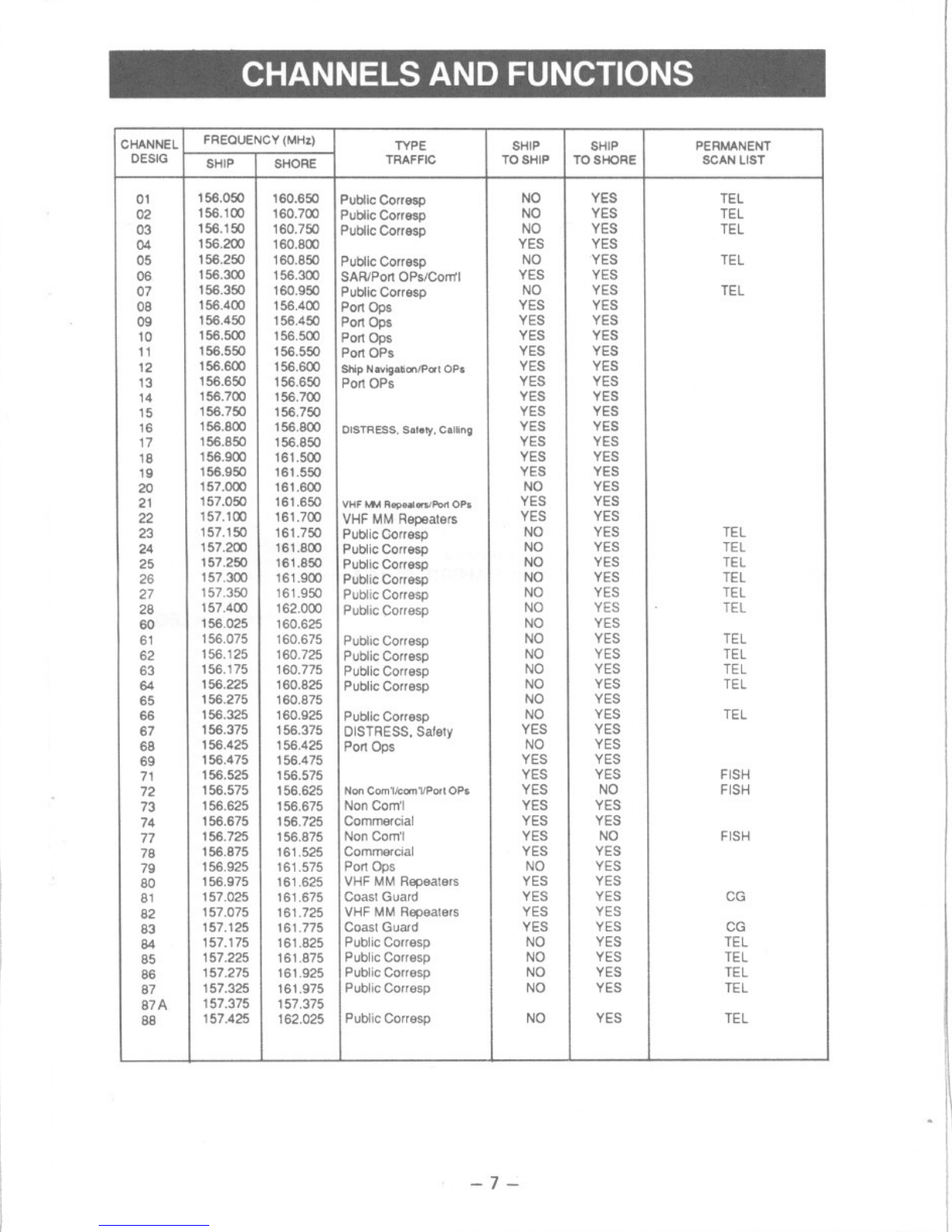
CHANNELS AND FUNCTIONS
CHANNEL
DESIG FREOUENCY (MHz)
SHIP ISHORE
SHIP
TOSHORE
TYPE
TRAFFIC SHIP
TOSHIP
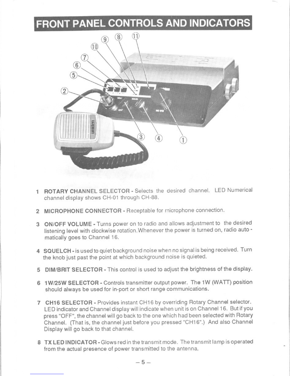
01
02
03
04
05
06
156.050
156.100
156.150
156.200
156.250
156.300
Public Corresp
Public Corresp
Public Corresp
Public Corresp
SAR/Port OPs/Com'1
NO
NO
NO
YES
NO
YES
YES
YES
YES
YES
YES
YES
160.650
160.700
160.750
160.800
160.850
156.300
PERMANENT
SCAN LIST
TEL
TEL
TEL
TEL
TEL
TEL
TEL
TEL
TEL
TEL
TEL
TEL
TEL
TEL
TEL
TEL
FISH
FISH
FISH
CG
CG
TEL
TEL
TEL
TEL
TEL
r
1
-
,06 1Ob.;'W lOb.;'W yt: yt:
07 156.350 160.950 PublicCorresp NO YES
08 156.400 156.400 Port Ops YES YES
09 156.450 156.450 Port Ops YES YES
10 156.500 156.500 Port Ops YES YES
11 156.550 156.550 Port OPs YES YES
12 156.600 156.600 ShipNavigation/PortOPs YES YES
13 156.650 156.650 Port OPs YES YES
14 156.700 156.700 YES YES
15 156.750 156.750 YES YES
16 156.800 156.800 DISTRESS.Safely.Calling YES YES
17 156.850 156.850 YES YES
18 156.900 161.500 YES YES
19 156.950 161.550 YES YES
20 157.000 161.600 NO YES
21 157.050 161.650 VHF r.f.ARepealers/Port OPs YES YES
22 157.100 161.700 VHFMMRepeaters YES YES
23 157.150 161.750 PublicOorresp NO YES
24 157.200 161.800 PublicCorresp NO YES
25 157.250 161.850 PublicCorresp NO YES
26 157.300 161.900 PublicCorresp NO YES
27 157.350 161.950 PublicCorresp NO YES
28 157.400 162.000 PublicCorresp NO YES
60 156.025 160.625 NO YES
61 156.075 160.675 PublicCorresp NO YES
62 156.125 160.725 PublicCorresp NO YES
63 156.175 160.775 PublicCorresp NO YES
64 156.225 160.825 PublicCorresp NO YES
65 156.275 160.875 NO YES
66 156.325 160.925 PublicCorresp NO YES
67 156.375 156.375 DISTRESS.Safety YES YES
68 156.425 156.425 Port Ops NO YES
69 156.475 156.475 YES YES
71 156.525 156.575 YES YES
72 156.575 156.625 NonCom'l/com'I/PortOPs YES NO
73 156.625 156.675 NonCom'l YES YES
74 156.675 156.725 Commercial YES YES
77 156.725 156.875 NonCom" YES NO
78 156.875 161.525 Commercial YES YES
79 156.925 161.575 Port Ops NO YES
80 156.975 161.625 VHFMMRepeaters YES YES
81 157.025 161.675 Coast Guard YES YES
82 157.075 161.725 VHFMMRepeaters YES YES
83 157.125 161.775 Coast Guard YES YES
84 157.175 161.825 PublicCorresp NO YES
85 157.225 161.875 PublicCorresp NO YES
86 157.275 161.925 PublicCorresp NO YES
87 157.325 161.975 PublicCorresp NO YES
87A 157.375 157.375
88 157.425 162.025 PublicCorresp NO YES
-7-
-
--.- . -. - -
-.