TQ KTX2 User manual
Document No. TQG191-IM
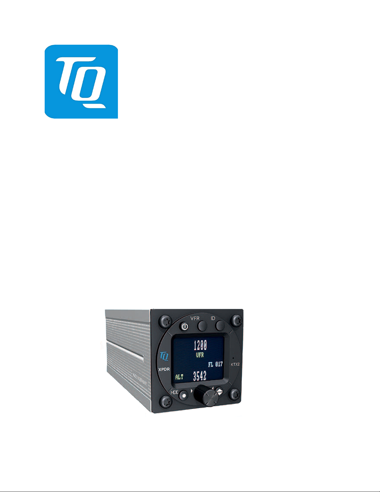
KTX2 MODE-S(ES) ADS-B TRANSPONDER
Part Number 304110 (XX)
Installation Manual
(Approved Model List Supplemental Type Certificate)
This manual contains installation instructions and recommended flight line maintenance
information for the KTX2 ADS-B Transponder System. Guidelines for external equipment
necessary for installation are included. This information is kept current by revisions, service
letters and service bulletins.

Page i TQG191-IM
Rev 0: 28 Feb 2019
KTX2
Installation Manual
FORWARD
This manual provides information intended for use by persons who, in accordance with current
regulatory requirements, are qualified to install this equipment. Installation requirements may vary,
depending on the particularities of each aircraft, and this manual is intended as a guideline for
that purpose. This manual assumes familiarity with the setup and operation of the aircraft
systems that interface with the KTX2.
If further technical information is required, please contact:
TQ-Group GmbH
Attn: Direct Service Support
Mühlstraße 2, 82229 Seefeld, Germany
Telephone: +49 (0)8153-9308-661
Fax: +49 (0)8153-9308-661
Email: support@tq-generaql-aviation.com
Website: https://www.tq-general-aviation.com/en/Service
We welcome your comments concerning this manual. Although every effort has been made to
keep it free of errors, some may occur. When reporting a specific problem, please describe it
briefly and include the manual part number, the paragraph/figure/table number, and the page
number. Send your comments to the STC Holder at:
ADS-B Technologies LLC
Attn: Technical Publications
819 Orca Street
Anchorage, AK 99501
Telephone: (907) 258-2372
Fax: (888) 499-2584
Email: service@ads-b.com
Website: https://www.ads-b.com
WARNING
INFORMATION SUBJECT TO EXPORT CONTROL LAWS
This technical data is controlled under the Export Administration Regulations (EAR) and
may not be exported without proper authorization by the U.S. Department of Commerce.
KTX2 is a registered trademark of TQ-Group

Page ii TQG191-IM
Rev 0: 28 Feb 2019
KTX2
Installation Manual
RECORD OF REVISIONS
Revision
Date of Revision
Description
0
28 Feb 2019
Original Issue

Page iii TQG191-IM
Rev 0: 28 Feb 2019
KTX2
Installation Manual
TABLE OF CONTENTS
SECTION 1!GENERAL INFORMATION ............................................................................... 1-1!
1.1!INTRODUCTION ....................................................................................................1-1!
1.2!DEFINITIONS .........................................................................................................1-1!
1.3!TERMINOLOGY .....................................................................................................1-2!
1.4!SCOPE ...................................................................................................................1-2!
1.4.1!Approved Aircraft With Systems Not Covered by the AML STC ...........................1-2!
1.5!INTRODUCTION ....................................................................................................1-2!
1.5.1!Functional Description .........................................................................................1-3!
1.5.2!ADS-B OUT Functional Overview ........................................................................1-4!
1.5.3!GPS Functional Overview ....................................................................................1-4!
1.5.4!Barometric Altitude Inputs ....................................................................................1-4!
1.5.5!Additional Interfaces ............................................................................................1-4!
1.6!EQUIPMENT DESCRIPTIONS ...............................................................................1-5!
1.7!TECHNICAL SPECIFICATIONS ............................................................................1-5!
SECTION 2!INSTALLATION INFORMATION ...................................................................... 2-1!
2.1!INTRODUCTION ....................................................................................................2-1!
2.2!PRE-INSTALLATION OVERVIEW .........................................................................2-1!
2.2.1!Unpacking and Inspection....................................................................................2-1!
2.2.2!Installation Planning.............................................................................................2-1!
2.3!PRE-INSTALLATION CHECKLIST ........................................................................2-2!
2.4!SUPPLIED EQUIPMENT .......................................................................................2-2!
2.5!EQUIPMENT REQUIRED BUT NOT SUPPLIED ...................................................2-2!
2.5.1!Optional Installation Kits – KTX2..........................................................................2-4!
2.5.2!Antenna Cables ...................................................................................................2-4!
2.6!PERIPHERAL EQUIPMENT INTERFACES ...........................................................2-4!
2.6.1!GPS Units and GPS Antennas ............................................................................2-4!
2.6.2!L-Band ADS-B Antennas ....................................................................................2-5!
SECTION 3!INSTALLATION INSTRUCTIONS ..................................................................... 3-6!
3.1!INTRODUCTION ....................................................................................................3-6!
3.2!LIMITATIONS ........................................................................................................3-6!
3.3!INSTALLATION PROCEDURES ...........................................................................3-6!
3.3.1!Equipment Location KTX2 ...................................................................................3-7!
3.3.2!Electrical Connections .........................................................................................3-8!
3.3.3!P1 Connector Assembly ....................................................................................3-10!
3.3.4!Mutual Suppression ...........................................................................................3-10!
3.3.5!Ground (WOW) Switch ......................................................................................3-11!
3.3.6!GPS Interface ....................................................................................................3-11!
3.3.7!Antenna Installation Guidelines .........................................................................3-11!
3.3.8!GPS Antenna.....................................................................................................3-12!
3.3.9!L-Band (1090MHz) Antenna ..............................................................................3-13!
3.3.10!Altitude Input .....................................................................................................3-14!

Page iv TQG191-IM
Rev 0: 28 Feb 2019
KTX2
Installation Manual
3.3.11!KTX2 Final Installation Steps .............................................................................3-14!
3.4!REQUIRED PLACARDS AND MARKINGS .........................................................3-14!
3.5!REMOVE AND REPLACEMENT PROCEDURES ...............................................3-14!
SECTION 4!INSTALLATION CHECKOUT ........................................................................... 4-1!
4.1!INTRODUCTION ....................................................................................................4-1!
4.2!BASIC DISPLAYS AND CONTROLS ....................................................................4-1!
4.2.2!Controls ...............................................................................................................4-2!
4.2.3!Display Indications ...............................................................................................4-3!
4.2.4!Extended Squitter (ADS-B) Indications ................................................................4-4!
4.3!NORMAL OPERATION ..........................................................................................4-5!
4.3.1!ON/OFF ...............................................................................................................4-6!
4.3.2!Select Transponder Modes ..................................................................................4-7!
4.3.3!Changing the Squawk ..........................................................................................4-7!
4.3.4!VFR Squawk........................................................................................................4-7!
4.3.5!Squawk IDENT ....................................................................................................4-8!
4.3.6!Flight / Ground Indication .....................................................................................4-8!
4.3.7!Adjustable Parameters in Operation Mode ..........................................................4-8!
4.4!CONFIGURATION SET-UP ...................................................................................4-9!
4.4.1!Entering Set-Up Mode .........................................................................................4-9!
4.4.2!Configuration Pages ..........................................................................................4-12!
4.4.3!Factory Reset ....................................................................................................4-17!
4.4.4!Test Menu .........................................................................................................4-18!
4.4.5!Errors and Warnings ..........................................................................................4-19!
4.5!POST-INSTALLATION CHECKOUT ...................................................................4-20!
4.5.1!General..............................................................................................................4-20!
4.5.2!KTX2 Operational Checks .................................................................................4-20!
4.5.3!GPS Source Check............................................................................................4-20!
4.5.4!ADS-B Out Check ..............................................................................................4-21!
4.5.5!Static System Check..........................................................................................4-21!
4.5.6!Electromagnetic Interference (E.M.I.) Check......................................................4-21!
4.5.7!Flight Test ..........................................................................................................4-23!
4.5.8!Installation Checkout Complete .........................................................................4-23!
SECTION 5!MAINTENANCE ................................................................................................ 5-1!
5.1!INTRODUCTION ....................................................................................................5-1!
5.2!CONTINUED AIRWORTHINESS............................................................................5-1!
5.2.1!Periodic Maintenance KTX2 ................................................................................5-1!
5.3!FAULT ISOLATION ...............................................................................................5-1!
5.4!RETURN TO SERVICE ..........................................................................................5-3!
5.5!DISPOSITION OF FAILED ITEMS .........................................................................5-3!
APPENDIX A FCC RELATED ISSUES ..................................................................................... 1!
A.1!RADIOFREQUENCY RADIATION EXPOSURE INFORMATION ............................. 1!
A.2!COMPLIANCE .......................................................................................................... 1!

Page v TQG191-IM
Rev 0: 28 Feb 2019
KTX2
Installation Manual
A.3!MODIFICATIONS ...................................................................................................... 1!
APPENDIX B CONFIGURATION AND CHECKOUT WORKSHEET.......................................... 1!
TABLE OF TABLES
Table 1-1: KTX2 General Description......................................................................................1-3!
Table 1-2: System Components ...............................................................................................1-3!
Table 1-3: Specifications for the KTX2 ....................................................................................1-5!
Table 1-4: Transmitter/Receiver Specifications ........................................................................1-6!
Table 2-1: Pre-Installation Checklist ........................................................................................2-2!
Table 2-2: Supplied Equipment ...............................................................................................2-2!
Table 2-3: Equipment List – KTX2 ..........................................................................................2-2!
Table 2-4: NexNav Mini GPS Interface Kit ..............................................................................2-4!
Table 2-5: Coaxial Cable Specifications ...................................................................................2-4!
Table 2-6: L-Band Antennas ...................................................................................................2-5!
Table 4-1: KTX2 Controls.........................................................................................................4-2!
Table 4-2: Indications ...............................................................................................................4-3!
Table 4-3: Extended Squitter and ADS-B Indications ...............................................................4-4!
Table 4-4: KTX2 Operations Menus .........................................................................................4-5!
Table 4-5: Transponder Modes ................................................................................................4-7!
Table 4-6: Errors and Warnings .............................................................................................4-20!
Table 5-1: Troubleshooting KTX2 ...........................................................................................5-2!
!
TABLE OF FIGURES
Figure 1-1: System Interface Overview ...................................................................................1-4!
Figure 3-1: Outline Dimensions for the KTX2 ..........................................................................3-7!
Figure 3-2: Panel Cutout Dimensions......................................................................................3-8!
Figure 3-3: KTX2 Interconnect Wiring Overview .....................................................................3-9!
Figure 3-4: Cable Harness Assembly ....................................................................................3-10!
Figure 3-5: Example of Antenna Mounting Locations ............................................................3-12!
Figure 3-6: Example of RF Antenna Mounting and Bonding in Composite Aircraft ................3-12!
Figure 4-1: Controls & Display Screen .....................................................................................4-1!
Figure 4-2: Start-Up Screen .....................................................................................................4-6!
Figure 4-3: Normal Operations Screen.....................................................................................4-6!
Figure 4-4: Moving Standby Squawk to Active Squawk............................................................4-7!
Figure 4-5: Squawk IDENT ......................................................................................................4-8!
Figure 4-6: FLY / GND .............................................................................................................4-8!
Figure 4-7:: Modify Flight ID .....................................................................................................4-8!
Figure 4-8: Display Brightness Adjustment ..............................................................................4-9!
Figure 4-9: GPS Data ..............................................................................................................4-9!
Figure 4-10: Entering Set-Up Mode .........................................................................................4-9!
Figure 4-11: Configuration Pages ..........................................................................................4-11!

Page vi TQG191-IM
Rev 0: 28 Feb 2019
KTX2
Installation Manual
ABOUT THIS MANUAL
SECTION 1 – GENERAL INFORMATION
This section provides the following information: unit configurations, unit functionality,
items required but not supplied with the unit, equipment specifications, installation
approval/limitations and TSO approvals.
SECTION 2 – INSTALLATION INFORMATION
This section contains instructions to locate, assemble and install the KTX2 as well as
information for unpacking equipment, and inspection procedure for in-shipment damage.
SECTION 3 – INSTALLATION INSTRUCTIONS
This section contains instructions for post installation setup, post installation and return
to service checkout.
SECTION 4 – INSTALLATION CHECKOUT
This section contains general flight line maintenance procedures. It includes periodic
maintenance, troubleshooting and instructions for the return of defective components.
SECTION 5 – MAINTENANCE
This appendix defines the electrical characteristics of all input and output signals.
DEFINITIONS OF WARNING, CAUTIONS AND NOTES
WARNING
Warnings are used to bring the Installer’s immediate attention to
potentially hazardous situations in which equipment damage or
personal injury may occur if the instructions are disregarded.
CAUTION
Cautions are used to alert the installer that equipment damage or a
deviation from the STC may occur if instructions are not followed to
the letter.
IMPORTANT INFORMATION
Important information is used to explain an installation step in greater
detail so that there will be no misunderstanding of the Installation
Instructions intent.

Page vii TQG191-IM
Rev 0: 28 Feb 2019
KTX2
Installation Manual
LIST OF EFFECTIVE PAGES
Total number of pages in this publication consist of the following:
Page of Section
Number of
Pages
Current revision
Title Page
1
Original
i thru vii
7
Original
1.1 thru 1.6
6
Original
2.1 thru 2.5
5
Original
3.1 thru 3.14
14
Original
4.1 thru 4.21
21
Original
5.1 thru 5.5
5
Original
Error! Reference
source not
found.
1
Original
Error! Reference
source not
found.
1
Original
DISCLAIMER
Information in this manual is subject to change without notice and will not be updated after
distribution. Changes to this manual will be reflected in the next revision. Revisions replace the
entire manual and are incorporated as needed in order to keep information accurate and up-to-
date
Avionics Systems does provide a listing of all publications and directives with their current
revision to insure up-to-date information. See www.tq-general-aviation.com to get an up-to-date
listing of all Avionics Systems technical publications and directives.
The software version and information in this document are subject to change without notice. Visit
https://www.tq-general-aviation.com/en/Service/Downloads for current updates and
supplemental information concerning the operation of this product.

Page 1-1 General Information TQG191-IM
Rev 0: 28 Feb 2019
KTX2
Installation Manual
SECTION 1 GENERAL INFORMATION
1.1 INTRODUCTION
This manual describes the physical, mechanical, and electrical characteristics as well as
instructions,
conditions, and limitations for installation and approval of the KTX2 Transponder
System.
1.2 DEFINITIONS
Acronym
Definition
AA
—
Aircraft Address – ICAO 24-bit address
AC
—
Advisory Circular, or Aircraft Category
ADS-B
—
Automatic Dependent Surveillance-Broadcast
AML
—
Approved Model List
APP
—
Application
ARINC
—
Aeronautical Radio, Incorporated
ATCRBS
—
Air Traffic Control Radar Beacon System
DL
—
Data Loading
DME
—
Distance Measuring Equipment
ETX
—
End of Transmission
FCC
—
Federal Communications Commission
FID
—
Flight ID
FPGA
—
Field Programmable Gate-Array
GND
—
Ground
GNSS
—
Global Navigation Satellite System
LRU
—
Line Replaceable Unit
NAS
—
National Airspace System
NOTAM
—
Notice to Airman
RAIM
—
Receiver Autonomous Integrity Monitoring
RF
—
Radio Frequency
RTCA
—
Radio Technical Commission for Aeronautics
RX
—
Receive
SBAS
—
Satellite-Based Augmentation System
SPE
—
Single Point Entry
STB
—
Standby
STC
—
Supplemental Type Certificate
TQ-G
—
TQ-Group
TSO
—
Technical Standard Order
TX
—
Transmit
WAAS
—
Wide Area Augmentation System

Page 1-2 General Information TQG191-IM
Rev 0: 28 Feb 2019
KTX2
Installation Manual
1.3 TERMINOLOGY
Except where specifically noted, references made to “the Unit” or “the Installation” will apply to
the KTX2. Likewise, the terms “1090 Transponder”, “Mode-S Transponder”, or “Transponder”
will also mean the KTX2. References to “metal aircraft” will refer to aircraft with an aluminum
skin. “Nonmetallic aircraft” will refer all other aircraft including composite, wood, or tube and
fabric construction.
1.4 SCOPE
This Installation Manual applies to the modification of an aircraft under AML STC SA02525AK
for the installation of the equipment described in Table 1-1. Interfaces between the equipment
listed in the second column and
the KTX2 are covered by this STC. This STC is only applicable
to the 14 CFR, Part 23, Class I, II and III aircraft, as defined in Advisory Circular (AC)
23.1309-l E, which are identified in the AML. Installations in 14 CFR, Part 23 Class IV, Part
25, Part 27 and Part 29 aircraft are not authorized under this AML STC.
Equipment Installation Covered under
AML STC
Equipment Required, but Installation NOT
Covered Under AML STC
•
KTX2 Transponder
•
GPS receiver
•
WAAS GPS Antenna
•
L-Band Antennas
•
Cables and connectors not included in the
Transponder factory ship kit
1.4.1 Approved Aircraft With Systems Not Covered by the AML STC
Aircraft on the AML have been determined to meet the minimum required configuration for
application of the STC. However, since some of these aircraft may have been modified since
they were manufactured under their original Type Certification, it may be difficult to use the data
herein to completely confirm that the installation is in compliance with the STC.
It is therefore the Installer’s responsibility to make the final determination of STC applicability for
each individual aircraft.
Use this manual to evaluate each installation prior to modifying a Type Certificated aircraft to
ensure applicability and compliance with AML STC SA02525AK. If in doubt, the Installer should
consider requesting Field Approval or a unique STC to perform the installation. Consult AC 43-
210 for guidance on the Field Approval process. Antennas, particularly when installed on
composite and pressurized aircraft, will normally require separate approval.
1.5 INTRODUCTION
This section includes descriptions, specifications, TSO information, and installation approval
and limitations for the KTX2. The KTX2 system (also referred to as the Transponder) includes a
KTX2 device, an interface to an approved GPS receiver and connections to recommended
antennas, the pitot-static system and a power source.
The system requires additional 3rd party components. A list of system components is provided in
Table 1-2. See Figure 1-1 for an overview of the unit’s system interface.
Included in SECTION 2, paragraph 2.5 is a list of compatible equipment and equipment required
but not supplied with the system.
Page 1-3 General Information TQG191-IM
Rev 0: 28 Feb 2019
KTX2
Installation Manual
Table 1-1: KTX2 General Description
MODEL/ P/N
DESCRIPTION
INTERFACES/FUNCTIONS
KTX2
P/N 304110-
XX(XX)XX-(XX)
Supports 1090 MHz Mode
S(ES) ADS-B OUT
•
Approved WAAS GPS RS-232 Input
•
Altitude data input (Static Port connection)
•
L-Band Antenna
Table 1-2: System Components
COMPONENT
MODELS
H/W PART NO.
Mode-S(ES) Transponder System
NTX2
304110-XX(XX)XX-(XX)
The following components are not supplied with the system, but are required.
COMPONENT
REFERENCE
COMMENTS
GPS Receiver
2.6.1
Required, but installation is not covered by this
STC
GPS Antenna
2.6.1
Required, but installation is not covered by this
STC
L-Band Antenna
Table 2-6
Required, but installation is not covered by this
STC
Static Source
3.3.10
An aircraft static source is required
1.5.1 Functional Description
The KTX2 is a panel mount Class 1 Non-Diversity Mode-S(ES) ADS-B OUT DO-260B compliant
transponder that meets the 2020 ADS-B Mandate requirements when connected to a WAAS
GPS source and appropriate L-Band antennas.
The unit receives Mode A, Mode C, and Mode S interrogations on 1030 MHz and replies on
1090 MHz. The unit is equipped with IDENT capability that activates the Special Identification
(SPI) pulse for 18 seconds. Ground stations and airborne TCAS II can interrogate Mode S
Transponders individually using a 24-bit ICAO Mode S address, which is unique to the particular
aircraft. In addition, ground stations may interrogate the unit for its transponder data capability
and the aircraft's Flight ID.
With a GPS source connected, the ADS-B Out (1090ES) function is used to periodically
broadcast (without interrogation) information about the aircraft that includes aircraft
identification, position, altitude, velocity and other aircraft status information. This provides an
immediate surveillance source to the ANSP and air-to-air traffic information to other aircraft.
The unit has been tested and certified for pressure altitudes up to 30,000 ft and a maximum
airspeed of 250 kts.
See Figure 1-1 for an overview of the unit’s system interface. The following paragraphs provide
an overview of each of these functions.
NOTE
With no GPS interface configured, or the GPS source
inoperable, the transponder is not ADS-B rule compliant
and will behave as a conventional Mode-S transponder.

Page 1-4 General Information TQG191-IM
Rev 0: 28 Feb 2019
KTX2
Installation Manual
Figure 1-1: System Interface Overview
1.5.2 ADS-B OUT Functional Overview
The ADS-B Out function supports the transmission of Automatic Dependent Surveillance –
Broadcast (ADS-B) Out on a 1090 MHz link. The ADS-B Out data contains information about
own aircraft such as aircraft position, velocity, direction, etc. The ADS-B function requires own
aircraft data from an external GPS receiver.
Control functions such as squawk codes, Ident, and operational mode (e.g. Mode "A", Mode
"C", etc.) are selected on the unit’s control panel.
1.5.3 GPS Functional Overview
The external GPS provides position, velocity, time and integrity (NIC, NAC, etc.) information to
the Transponder. This GPS source must be rule compliant with the position source
requirements of AC20-165A. The external GPS source must support WAAS. Note that the
NexNav mini is currently the only compatible GPS source.
1.5.4 Barometric Altitude Inputs
In addition to GPS altitude, the KTX2 has a
Temperature compensated
high
precision
piezo-
resistive pressure sensor that provides barometric altitude when connected to a calibrated
aircraft static source.
1.5.5 Additional Interfaces
The WOW input discrete is optional. The input signals the “On Ground” status to the
Transponder via a gear switch or squat switch.
The RF Suppression connection is optional. When other avionics utilizing the same frequency
band as the Transponder are installed (e.g. DME), this connection will suppress transmission
from a competing transmitter for the duration of the ADS-B transmission.

Page 1-5 General Information TQG191-IM
Rev 0: 28 Feb 2019
KTX2
Installation Manual
1.6 EQUIPMENT DESCRIPTIONS
The KTX2 is equipped with a 15-pin sub-D connector (J1) and miniature RF connectors for L-
Band OUT (ANT) and an optional L-Band accessory (LOOP).
The KTX2 can interface with a compatible external GPS source via pins 2 and 13 on connector
P1;
Mutual Suppression is configured via pin 12 on connector P1;
The Weight on Wheels “On Ground” function is enabled by grounding pin 5 on P1;
±14/28 VDC from the aircraft battery buss or avionics Master Switch is connected via pin 8
(positive) and pin 1 (negative/ground) on P1.
Pins 10 and 6 are not normally connected and are reserved for future use.
1.7 TECHNICAL SPECIFICATIONS
Table 1-3 lists the specifications, certification and compliance standards for the KTX2
transponder. Table 1-4 lists the specifications for the transmitter and receiver sections.
Table 1-3: Specifications for the KTX2
Part Number:
304110-XX(XX)-XX(XX) KTX2 Mode S Transponder
Authorization:
EASA.210.10069784
Certification:
ETSO-C112d / TSO-C112d
ETSO-C88a / TSO-C88a
ETSO-C166b / TSO-C166b
Advisory Circulars:
AC 20-165A (ADS-B Out)
Compliance:
RTCA DO-181E /. ED-73E / Level 2els,Class 1
RTCA DO-178C/ ED-12C Level D
RTCA DO-254 / ED80 Level C
RTCA DO-160G / ED-14G
RTCA DO-260B / ED102A Class B1S
CFR 91.225 and CFR 91.227
FCC ID: 2ANFF-KTX2S
Other Standards: SAE AS8003, AC 20-165A
Environmental Compliance:
DO-160F, Cat S Vibration Curve M, Cat A
Operation -20 ºC to +55 ºC (-4 ºF to +131 ºF)
Storage -55 ºC to +85 ºC (-67 ºF to +185 ºF)
Dimensions:
Height 2.44 inch [62 mm]
Width 2.48 inch [63 mm]
Length 5.86 inch [149 mm] (body only)
Bezel 2.24 inch [57 mm] diameter (standard 2¼” cutout)
Weight:
0.83 lb. [0.381Kg]
Maximum Altitude:
30,000 ft
Shock:
6G Operation
20G Crash Safety
Chassis Ground:
Bonding impedance between aircraft ground and the chassis must
be less than 2.5 milliohms.
Power Requirements:
9 Vdc to 33 VDC; 0.2A to 1.0A (Illumination 0.02A)

Page 1-6 General Information TQG191-IM
Rev 0: 28 Feb 2019
KTX2
Installation Manual
Table 1-3: Specifications for the KTX2
External Breaker required: 3A (14 VDC); 2A (28 VDC), slow-blow.
Emergency Operation capable down to 9 VDC
Electrical Connectors:
J1 is a 15-pin D-Sub male connector that mates with P1, a 15-pin
D-Sub female connector with a backshell.
Operating Temperature:
-20° to +55°C (-4° to +131°F)
Storage Temperature:
-55° to +85°C (-67° to +185°F)
Maximum Altitude:
30,000 ft (9,144 meters)
Compass Security Distance:
30 cm [12”]
Scheduled Maintenance:
None
Service Life:
The unit has unlimited service life.
Repairability:
Repairs performed at an FAA certificated Repair Station.
Table 1-4: Transmitter/Receiver Specifications
Receiver Sensitivity:
RF input power level resulting in a 90% reply rate:
• MTL for ATCRBS and ATCRBS/Mode S All-Call
interrogations: -74dBm ±3dB.
• MTL for Mode S interrogations: -74dBm ± 3dB.
Reply Frequency:
1090 ± 1MHz
RF Peak Power:
≥ 21 dBW (125 W) at antenna base (with maximum cable
attenuation of 1.5 dB)
Squitter:
Transmitted at random intervals uniformly distributed over the
range from 0.8 to 1.2 seconds, with full self- verification of data
and occurrence

Page 2-1 Installation Instructions TQG191-IM
Rev 0: 28 Feb 2019
KTX2
Installation Manual
SECTION 2 INSTALLATION INFORMATION
2.1 INTRODUCTION
The following section contains an overview of the steps required for the installation of the KTX2
and
its related components. This section includes requirements for selection of proper locations
in the aircraft as well
as requirements for supporting structure, mechanical alignment, and
electrical wiring. Any restrictions related to nearby equipment and requirements are also
specified herein.
Always follow acceptable avionics installation practices as set forth in FAA Advisory Circulars
(AC) 43.13-1B,
43.13-2B, or later revisions of these documents.
2.2 PRE-INSTALLATION OVERVIEW
2.2.1 Unpacking and Inspection
Carefully unpack the unit and note any damage to shipping containers or equipment. Visually
inspect each component for evidence of damage. Compare the equipment received with that
noted on the packing list. Report immediately any missing items or evidence of damage to the
carrier making the delivery. To justify a claim, retain the original shipping container and all
packing materials.
Every effort should be made to retain the original shipping containers for storage. If the original
containers are not available, a separate cardboard container should be prepared that is large
enough to accommodate sufficient packing material to prevent movement.
2.2.2 Installation Planning
A successful installation starts with careful planning, including determination of mounting
locations
for the KTX2, cable routing, ventilation, ease of access and other required modifications.
After choosing a mounting location:
Consider the structural integrity of the desired installation location in accordance with AC 43.13-
2B, Chapter 1.
Complete a weight and balance computation before
beginning the installation.
An electrical load analysis (ELA) must be completed on the aircraft both prior to installation and
after the installation has been completed to verify that the aircraft electrical system is capable of
supporting the KTX2. Table 1-4 and Table 1-6 specify the power requirements for the equipment
and MIL – E – 7016F and the Aircraft Manufacturer can provide guidance on ELA methods and
maximum permissible loads. The purpose of the ELA is to show
compliance with 14 CFR
23.1351.
Follow the installation procedures in this installation manual as they are presented for a
successful
installation. Please familiarize yourself with this manual in its entirety before
beginning the procedure.

Page 2-2 Installation Instructions TQG191-IM
Rev 0: 28 Feb 2019
KTX2
Installation Manual
2.3 PRE-INSTALLATION CHECKLIST
Before beginning the installation, ensure that the aircraft and all associated equipment meet the
requirements of the AML STC and government regulations. This pre-Installation Checklist,
Table 2-1, should be completed before any aircraft or equipment modification begins.
Table 2-1: Pre-Installation Checklist
ITEM
REFERENCE
Or Section
✔
Aircraft is on AML?
SA02525AK
❏
An Electrical Load Analysis has been performed to ensure that the electrical
system is sufficient for the installation
2.2.2
❏
Is there a compatible GPS installed in aircraft?
2.6.1
❏
All peripheral equipment (GPS Source, antennas, coax, etc.) are approved
under STC or a Field Approval
2.5
❏
There is adequate space, structural integrity and ventilation (if required) for
all installed equipment
2.2.2
❏
There is an acceptable L-Band antenna location on bottom of aircraft
3.3.9
❏
All equipment has been unpacked and inspected for damage.
2.2.1
❏
Equipment received has been compared to packing list(s)
2.2.1
❏
2.4 SUPPLIED EQUIPMENT
The equipment supplied for a typical KTX2 installation is listed in Table 2-2.
Table 2-2: Supplied Equipment
Part Number
Description
Qty
304110-XX(XX)-XX(XX)
KTX2
1
2.5 EQUIPMENT REQUIRED BUT NOT SUPPLIED
Use Table 2-3 to identify equipment required for installation, calibration and testing of the KTX2.
Equivalent tools, equipment and hardware may be used provided they meet the standards
described in FAA Advisory Circulars (AC) 43.13-1B, 43.13-2B, or later revisions of these
documents.
Table 2-3: Equipment List – KTX2
ITEM
DESCRIPTION
Cables and
Wiring:
The installer supplies all system wires and cables.
Mating Connector (P1)
•
Wires are 22 AWG (signal) or 20 AWG as noted on interconnect wiring
diagram in section 2. Use M22759 or equivalent wire for installation.
•
wiring diagram.
Antenna Cables
•
L-Band Antenna
Require RG400 or equivalent coaxial cable. For the L-Band antenna the
attenuation must not exceed 1.5 dB per cable (including the connectors).
Refer to Table 2-5.
•

Page 2-3 Installation Instructions TQG191-IM
Rev 0: 28 Feb 2019
KTX2
Installation Manual
Table 2-3: Equipment List – KTX2
ITEM
DESCRIPTION
NOTE
RG type coaxial cable insertion loss can vary significantly between
manufacturers. Refer to the cable manufacturer's specification sheet for
actual attenuation (insertion loss) for the cable being used.
Circuit
Breaker:
Installer is responsible for determining appropriate circuit breakers needed to protect
aircraft wiring. The installation requires the following circuit breakers:
•
3.0 amp slow-blow circuit breaker for the installations with 14VDC input.
•
2.0 amp slow-blow circuit breaker for the installations with 28VDC input.
Consumables:
Antenna Sealant
•
For pressurized aircraft, use a sealant that meets the requirements of SAE
AMS-S-8802 such as Flamemaster® CS3204 class B. For non-pressurized
aircraft, use a non-corrosive sealant that meets the physical requirements of
MIL-A-46146 such as General Electric RTV162.
Surface Preparation
•
Alodine® No. 1001 required for installation of the antenna.
Hardware:
The following items are commercially available from aviation suppliers or other
reputable sources and are the responsibility of the installer:
•
Ring Terminals (For Grounding).
•
Solder Sleeves.
•
Cable tie/Tie wrap.
•
Ground Braid (RAY-101-20.0/AA59569R36TXXXX or equivalent).
•
Coaxial connectors.
•
Fusion tape.
Installation
Kits:
Installation Kits for the KTX2 are a customer option and are ordered separately.
Installation
Tools:
•
Insertion/Extraction tool CIET-20HD.
•
Crimp Tool: P/N: M22520/2-01.
•
Positioner: P/N: M22520/2-08.
•
Heating tool and reflector: PR-25 or PR-25D and HL1802E-ADAPT. (Tyco
Electronics) for solder sleeves.
Software:
All operating software is pre-installed
System
Components:
The following system components must be purchased separately and do not come
with the KTX2 transponder:
•
GPS Source (NexNav Mini, or equivalent) and GPS antenna, L-Band
antenna. A list of compatible components is found in paragraph 2.6.
Test
Equipment:
Air Data Test Set
•
Required to test altitude inputs.
Flightline Tester
•
IFR-6000 Ramp Test Set (with ADS-B upgrade package, Manufacturer:
AEROFLEX.
Milliohm Meter
•
Required to check installation bonding to aircraft structure.
Page 2-4 Installation Instructions TQG191-IM
Rev 0: 28 Feb 2019
KTX2
Installation Manual
2.5.1 Optional Installation Kits – KTX2
Installations using the NexNav Mini may order the NexNav Mini installation kit. Refer to Table
2-4 for details.
Table 2-4: NexNav Mini GPS Interface Kit
Part Number
Description
Qty
312873.0100
Harness for KTX2 interface to NexNav Mini
1
2.5.2 Antenna Cables
Table 2-5 lists examples of the recommended L-Band antenna cable vendors and the type of
cable to be used for specific lengths of cable. Any cable meeting these specifications is
acceptable for the installation.
Table 2-5: Coaxial Cable Specifications
Insertion Loss
(dB/100ft) [1]
Carlisle IT Type
MIL-C-17 Type
RG Type
18.5
N/A
M17/128-RG400
RG-400
11.1
N/A
M17/112-RG304
RG-304
9.2
N/A
M17/127-RG393
RG-393
15.2
3C142B
N/A
N/A
9.2
311601
N/A
N/A
7.5
311501
N/A
N/A
5.8
311201
N/A
N/A
3.8
310801
N/A
N/A
[1] RG type coaxial cable insertion loss can vary significantly between manufacturers. The insertion
loss for RG type cables shown in this column is considered 'worst case'. Refer to the cable
manufacturer's specification sheet for actual attenuation (insertion loss) for the cable being used.
2.6 PERIPHERAL EQUIPMENT INTERFACES
Only the equipment listed in this section is recommended for use with the KTX2 system.
2.6.1 GPS Units and GPS Antennas
A WAAS GPS that is compliant with TSO-C145c must be connected to pins 2 and 13 to meet
the requirements of TSO C-166b for Rule-Compliant Mode S (ES) ADS-B Out. Note that the
NexNav mini is currently the only compatible GPS source.
NOTE
This AML STC does not confer FAA approval for installation of a
GPS receiver and a GPS antenna. Unless these installations have
previously received FAA approval, or are covered by a Manufacturer’s
STC, additional FAA approval will be required. Also consult the
applicable Aircraft Structural Repair Manual for approved locations,
methods and additional restrictions pertaining to these installations.

Page 2-5 Installation Instructions TQG191-IM
Rev 0: 28 Feb 2019
KTX2
Installation Manual
2.6.2 L-Band ADS-B Antennas
The L-Band antenna used with the KTX2 must adhere to the following specifications:
Standard 50 W, vertically polarized antenna with a VSWR < 1.7:1 at 1090 MHz.
TSO-C66( ), TSO-C74( ), TSO-C112( ) , or TSO-154c antennas that also meet the VSWR
specification.
Only the L-Band antennas listed in Table 2-6 have been tested for compatibility with
KTX2 installations.
Table 2-6: L-Band Antennas
Manufacturer
Part Number
Connector Type
RAMI
AV-74
BNC
Comant
CI-105
BNC
Comant
CI-105-11
TNC

Page 3-6 Installation Instructions TQG191-IM
Rev 0: 28 Feb 2019
KTX2
Installation Manual
SECTION 3 INSTALLATION INSTRUCTIONS
3.1 INTRODUCTION
This section provides installation information for the KTX2 ADS-B Transponder System.
Installations must be made by qualified personnel in conformance with applicable government
regulations.
3.2 LIMITATIONS
1. The KTX2 transceiver must use an L-Band antenna meeting the requirements
specified in paragraph 2.6.2.
2. The KTX2 must use a GPS source meeting the requirements in paragraph 2.6.1.
3. It is the installer’s responsibility to follow the installation instructions in order to ensure
that the ADS-B Out system is compliant with AC 20-165A, 14 CFR 91.225 (b) and
91.227.
3.3 INSTALLATION PROCEDURES
1. The installer must take the following into consideration prior to installation:
• Follow the FAA approved AML STC installation instructions.
• Ensure the units are properly unpacked and inspected per paragraph 2.2.1.
• Follow the acceptable avionics installation practices in FAA Advisory AC 43.13-2B or
later revisions to this document.
• Installers are responsible for obtaining installation hardware (i.e. screws, supporting
plates, etc). Installation kits may be available for purchase. Refer to the Equipment
Required Not Supplied, paragraph 2.5.
• It is recommended that the aircraft battery be disconnected before performing
installation procedure.
• L-band and GPS antenna cables should be clearly labeled to prevent inadvertently
installing on the wrong connector.
• Tighten all screws to snug (i.e. only such torque that can be applied by hand) unless
specific torque instructions are given.
• After installation, refer to the Installation Checkout section for calibration, power-up
and ground testing procedures.
2. Electrical equipment chassis, shield/ground terminations, antennas, supporting brackets,
and racks must be electrically bonded to the aircraft's main structure (metallic aircraft) or
instrument panel (composite aircraft). Compliance of the electrical bonding should be
verified by inspection using a calibrated milliohm meter. An equivalent OEM procedure
may also be substituted.
• The electrical bond should achieve direct current (DC) resistance less than or equal to
2.5 mW to structure local to where the equipment is mounted for metallic aircraft or tube
and fabric aircraft.
• The electrical bond should achieve direct current (DC) resistance less than or equal to
5.0 mW to the instrument panel for composite aircraft.
3. The antenna ground plane must be electrically bonded to the antenna baseplate. Do not
Other manuals for KTX2
2
Table of contents
Other TQ Marine Radio manuals


