TQ KTX2 Specification sheet

TQ Aviation KTX2.0300
EASA.AP445 MAN
KTX2.A-MAN.0202.en.docx Page 2 of 49
© TQ-Systems GmbH. All information contained in this documents have to be treated strictly confidential. The transfer of presentations and know-how to third parties
requires the prior written consent of TQ-Systems GmbH.
KTX2
Mode-S Transponder
Standard
KTX2-S (Standard) with ADS-B with Part-No 304110
Operation and Installation
Manual

TQ Aviation KTX2.0300
EASA.AP445 MAN
KTX2.A-MAN.0202.en.docx Page 3 of 49
© TQ-Systems GmbH. All information contained in this documents have to be treated strictly confidential. The transfer of presentations and know-how to third parties
requires the prior written consent of TQ-Systems GmbH.
Revision List
Revision Date Topic
0100 24.03.2017 Initial Release
0101 20.02.2018 Amendments for extended Squitter and maintenance
0201 10.04.2019 Change due to new microcontroller and new functionalities ac-
cording to EUROCAE ED-102A / RTCA DO-260B
0202 17.04.2019 Amendment of Software License Clearing and added Cap. 10
Service Bulletins (SB)
Service Bulletins must be inserted in the manual and added to this table.
No SB No Rev. Release date Date Added Name

TQ Aviation KTX2.0300
EASA.AP445 MAN
KTX2.A-MAN.0202.en.docx Page 4 of 49
© TQ-Systems GmbH. All information contained in this documents have to be treated strictly confidential. The transfer of presentations and know-how to third parties
requires the prior written consent of TQ-Systems GmbH.
Change History
Product
Revision Date Description of Change
0300 09.04.2019 Base version for KTX2-S (Standard) with ADS-B
with Part-No 304110

TQ Aviation KTX2.0300
EASA.AP445 MAN
KTX2.A-MAN.0202.en.docx Page 5 of 49
© TQ-Systems GmbH. All information contained in this documents have to be treated strictly confidential. The transfer of presentations and know-how to third parties
requires the prior written consent of TQ-Systems GmbH.
Table of Contents
1. General ............................................................................................................................. 7
1.1. Symbols .................................................................................................................................... 7
1.2. Abbreviations ............................................................................................................................ 8
1.3. Customer Support ..................................................................................................................... 9
1.4. Features.................................................................................................................................. 10
2. Operation ................................................................................................................................ 11
2.1. Controls and Display on the Screen ........................................................................................ 11
2.1.1. Controls........................................................................................................................... 12
2.1.2. Indications ....................................................................................................................... 13
2.1.3. Operation menu structure................................................................................................ 14
2.1.4. ON/OFF........................................................................................................................... 15
2.1.5. Adjusting the Squawk ...................................................................................................... 16
2.1.6. Transponder-Modes ........................................................................................................ 17
2.1.7. VFR – Squawk ................................................................................................................ 17
2.1.8. Squawk Ident (ID, SPI) .................................................................................................... 18
2.1.9. Flight/Ground Indication................................................................................................... 18
2.2. Adjustable parameters in operation mode ............................................................................... 19
2.2.1. Flight ID........................................................................................................................... 19
2.2.2. Flight ID........................................................................................................................... 19
2.2.3. GNSS Data...................................................................................................................... 20
2.2.4. Extended Squitter............................................................................................................ 21
3. Set-Up..................................................................................................................................... 22
3.1. Entering Set Up....................................................................................................................... 24
3.1.1. Display brightness ........................................................................................................... 24
3.1.2. Set Flight-IDentifier (FID)................................................................................................. 25
3.1.2.1. Multiple Flight ID’s and Aircraft addresses....................................................................... 26
3.1.3. Aircraft Address (AA)....................................................................................................... 27
3.1.4. Device Parameter............................................................................................................ 28
3.1.4.1. Aircraft Category.............................................................................................................. 29
3.1.4.2. Ground Switch................................................................................................................. 30
3.1.4.3. Speed Category .............................................................................................................. 30
3.1.4.4. Select GNSS Device ....................................................................................................... 31
3.1.4.5. Select Length/Width ........................................................................................................ 32
3.1.4.6. GNSS Antenna Offset ..................................................................................................... 32
3.1.5. Modify VFR...................................................................................................................... 33
3.1.6. Factory Reset.................................................................................................................. 34
3.1.7. Test Menu ....................................................................................................................... 34
3.1.7.1. Altitude offset................................................................................................................... 35
3.1.7.2. Test Mode ....................................................................................................................... 35
3.1.7.3. Device Info ...................................................................................................................... 35
4. Errors and Warnings ............................................................................................................... 36
4.1. Setup Error.............................................................................................................................. 36
4.2. Critical Errors .......................................................................................................................... 36
4.2.1. Error FPGA...................................................................................................................... 37
4.2.2. Internal Communication failure ........................................................................................ 37
4.2.3. Do System Restart .......................................................................................................... 37
4.3. General Failure ....................................................................................................................... 37
4.3.1. CRC Failure..................................................................................................................... 37
4.4. Warnings................................................................................................................................. 38

TQ Aviation KTX2.0300
EASA.AP445 MAN
KTX2.A-MAN.0202.en.docx Page 6 of 49
© TQ-Systems GmbH. All information contained in this documents have to be treated strictly confidential. The transfer of presentations and know-how to third parties
requires the prior written consent of TQ-Systems GmbH.
4.4.1. Battery Warning............................................................................................................... 38
4.4.2. Antenna Warning............................................................................................................. 38
4.4.3. TRX Warning................................................................................................................... 39
5. Installation............................................................................................................................... 40
5.1. Equipment Connections .......................................................................................................... 40
5.1.1. Electrical Connections ..................................................................................................... 40
5.1.2. Mutual Suppression......................................................................................................... 40
5.1.3. Ground Switch................................................................................................................. 40
5.1.4. Static Air Port .................................................................................................................. 40
5.1.5. Interface .......................................................................................................................... 41
5.2. Wiring...................................................................................................................................... 42
5.2.1. Conductor Cross Section................................................................................................. 42
5.2.2. Wiring Scheme ................................................................................................................ 42
6. Drawings ................................................................................................................................. 43
7. Technical Data ........................................................................................................................ 44
7.1. General ................................................................................................................................... 44
7.2. Transmitter - Receiver............................................................................................................. 45
8. FCC related issues.................................................................................................................. 46
8.1. Radiofrequency radiation exposure Information: ..................................................................... 46
8.2. Notice...................................................................................................................................... 46
8.3. Compliance ............................................................................................................................. 46
8.4. Modifications ........................................................................................................................... 46
9. Maintenance ........................................................................................................................... 47
9.1. Periodic Maintenance.............................................................................................................. 47
9.2. Repair ..................................................................................................................................... 47
9.3. Cleaning.................................................................................................................................. 47
10. Software License Conformity................................................................................................... 48
List of Figures
Figure 1: Display Diagram..................................................................................................................11
Figure 2: Controls ..............................................................................................................................12
Figure 3: Indicators ............................................................................................................................13
Figure 4: Operational menu structure.................................................................................................14
Figure 5: Extended Squitter ...............................................................................................................21
Figure 6: Button functions in setup-mode...........................................................................................22
Figure 7: Setup menu structure..........................................................................................................23
Figure 8: Wiring .................................................................................................................................42
Figure 9: Dimensions of KTX2-S Standard round format....................................................................43
Figure 10: Technical Data ..................................................................................................................44
Figure 11: Transmitter receiver ..........................................................................................................45
TQ Aviation KTX2.0300
EASA.AP445 MAN
KTX2.A-MAN.0202.en.docx Page 7 of 49
© TQ-Systems GmbH. All information contained in this documents have to be treated strictly confidential. The transfer of presentations and know-how to third parties
requires the prior written consent of TQ-Systems GmbH.
1.
General
This manual contains information about the physical, mechanical and electrical characteristics,
installation and operation of the Mode S Transponder KTX2.
1.1.
Symbols
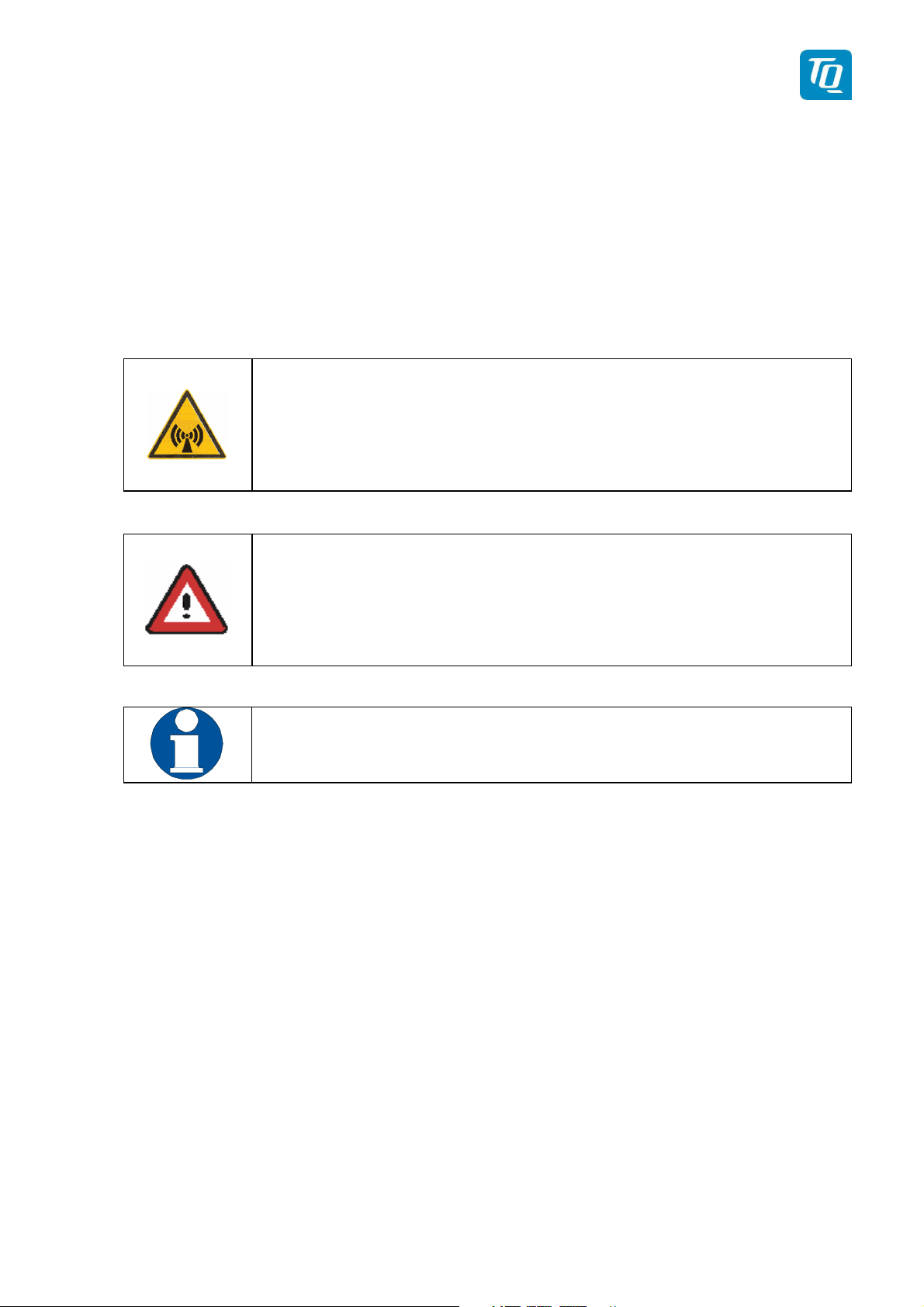
DANGER:
Advices whose non-observance can cause radiation dam-
age to the human body or ignition of combustible materi-
als.
ATTENTION:
Advices whose non-observance can cause damage to the
device or other parts of the equipment. or reduce the correct
functionality of the device.
INFORMATION

TQ Aviation KTX2.0300
EASA.AP445 MAN
KTX2.A-MAN.0202.en.docx Page 8 of 49
© TQ-Systems GmbH. All information contained in this documents have to be treated strictly confidential. The transfer of presentations and know-how to third parties
requires the prior written consent of TQ-Systems GmbH.
1.2.
Abbreviations
Abb.
Meaning
Explanation
FID Flight ID Flightplan Number or if not
assigned Regis-
tration Number of aircraft
SPI Special Position Identifica-
tion (ID)
Activation on request by controllers
„Squawk Ident“, transmits SPI Pulse for 18
seconds, which highlights the respective
traffic item on the controllers radar screen
AA Aircraft Address Assigned ICAO 24 bit address
AC Aircraft Category Defines aircraft type into specific catego-
ries
RI Reply Information Classified air speed
ADS-B Automatic Dependent Sur-
veillance Broadcast
-

TQ Aviation KTX2.0300
EASA.AP445 MAN
KTX2.A-MAN.0202.en.docx Page 9 of 49
© TQ-Systems GmbH. All information contained in this documents have to be treated strictly confidential. The transfer of presentations and know-how to third parties
requires the prior written consent of TQ-Systems GmbH.
1.3.
Customer
Support
In order to facilitate a rapid handling of returned shipments, please send your request at
the email address below. Additional information and FAX number can be found on the
TQ Avionics web portal:
www.tq-avionics.com
Any suggestions for improvement manuals are
welcome. Contact: info@tq-avionics.com
Information on software updates are available at TQ.
www.tq-avionics.com

TQ Aviation KTX2.0300
EASA.AP445 MAN
KTX2.A-MAN.0202.en.docx Page 10 of 49
© TQ-Systems GmbH. All information contained in this documents have to be treated strictly confidential. The transfer of presentations and know-how to third parties
requires the prior written consent of TQ-Systems GmbH.
1.4.
Features
•Class 1 Level 2els Non-Diversity Mode-S-Transponder for ground based inter-
rogations at 1030 MHz and response at 1090 MHz
•Replies to Secondary Radar Interrogations
oMode-A replies with a Squawk (one of 4096 possible Codes; e.g. flight
plan number, Squawk assigned by a Controller or the VFR Squawk).
oMode C replies, including Encoded Flight Level.
oMode S replies, including Aircraft Address and Flight Level.
oEvent Squitter, containing Identification Information.
oExtended Squitter, including position data.
•IDENT capability for activating the Special Position Identification“- Pulse (SPI)
for 18 seconds, which is requested by the Controller „Squawk Ident“
•Maximum flight level 30 000ft; maximum airspeed 250kt
•Display information contains Squawk code, mode of operation and pressure alti-
tude.
•
Temperature compensated
high
precision
piezo-resistive pressure sensor
•RS-232 data port enabling connection with mutual suppression and On the
Ground (weight on wheels) inputs. In addition, an appropriate GPS receiver for
“extended squitter” can be connected.
•8 storable entries for AA-/AC-Code, FID,
•
Ground-Switch support, RI-Code.
In order to operate the Mode-S transponder it is necessary to re-
quest (in time) an ICAO 24-Bit Aircraft Address at the responsible
National Aviation Authorities. The received code must be config-
ured within the transponder (see chapter. 3.1.2 “Flight-ID (FID) &
Set-Up”).

TQ Aviation KTX2.0300
EASA.AP445 MAN
KTX2.A-MAN.0202.en.docx Page 11 of 49
© TQ-Systems GmbH. All information contained in this documents have to be treated strictly confidential. The transfer of presentations and know-how to third parties
requires the prior written consent of TQ-Systems GmbH.
2.
Operation
2.1.
Controls
and Display on the Screen
Figure 1: Display Diagram
TQ Aviation KTX2.0300
EASA.AP445 MAN
KTX2.A-MAN.0202.en.docx Page 12 of 49
© TQ-Systems GmbH. All information contained in this documents have to be treated strictly confidential. The transfer of presentations and know-how to third parties
requires the prior written consent of TQ-Systems GmbH.
2.1.1.
Controls
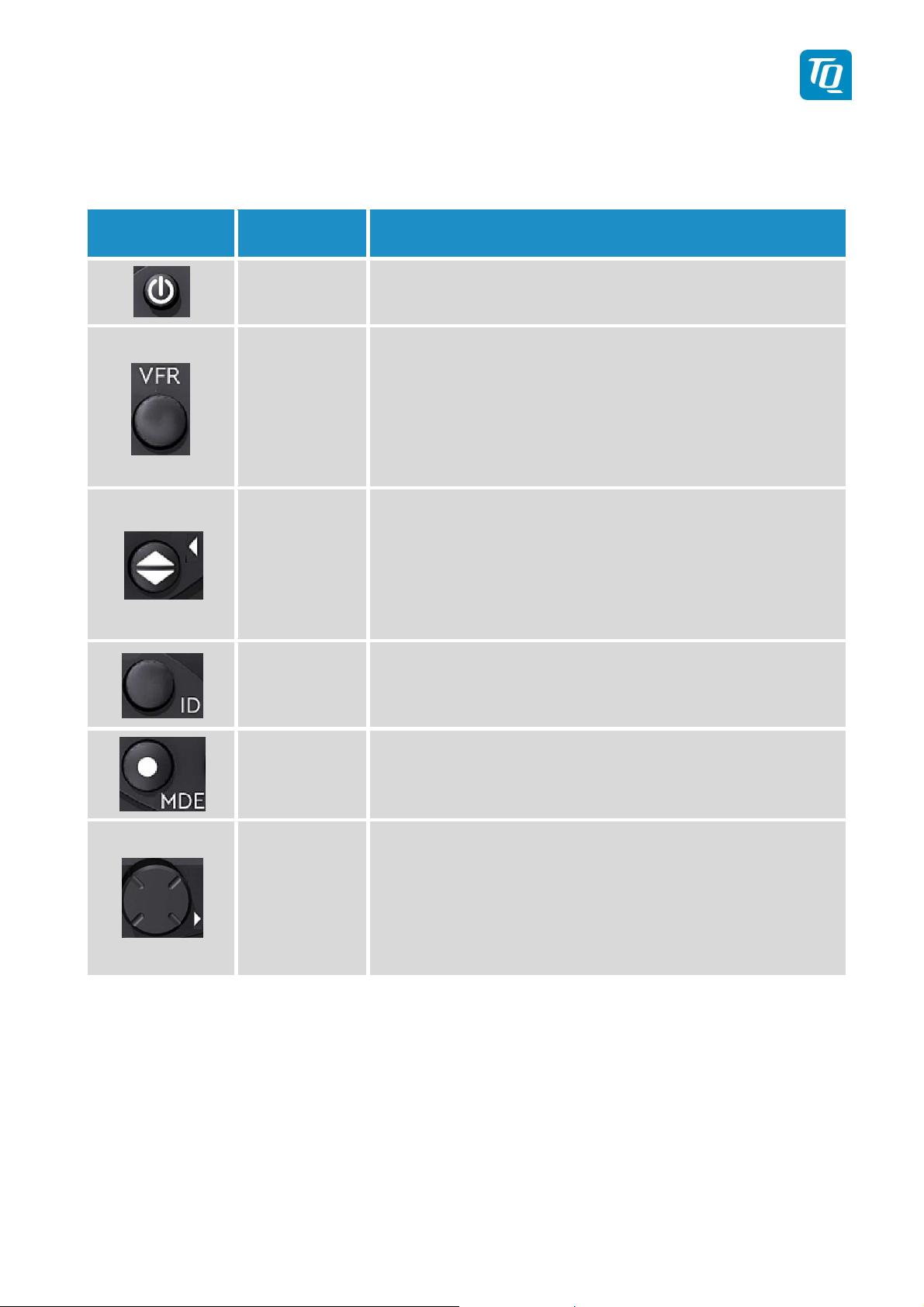
Key Designation Function
ON/OFF Push = ON. This switch is mechanically locked until it
is pushed a second time.
VFR
Activate/deactivate VFR Squawk
(press shortly)
Store the standby Squawk as VFR/VFRW-
Squawk (press button 3 s) see chapter “2.6 VFR –
Squawk”.
CHANGE
1.
Exchange of the active and standby-Squawk
2.
Works as cursor back button when entering values
and also for navigating backwards through the con-
figuration menu.
IDENT
„Squawk Ident“, sends Ident marking (SPI) for 18s (in
normal mode) see chapter. “2.9 Flight- ID (FID) &
Set-Up”
MODE
Select Transponder-Mode ACS, A-S or
Standby (see chapter “2.4 Transponder-
Modes”)
Rotary knob
1. Enter values at current cursor position, select op-
tions; set standby Squawk
2. Works as cursor forward button when entering
values and also for navigating forward through
the configuration menu.
Figure 2: Controls
TQ Aviation KTX2.0300
EASA.AP445 MAN
KTX2.A-MAN.0202.en.docx Page 13 of 49
© TQ-Systems GmbH. All information contained in this documents have to be treated strictly confidential. The transfer of presentations and know-how to third parties
requires the prior written consent of TQ-Systems GmbH.
2.1.2.
Indications
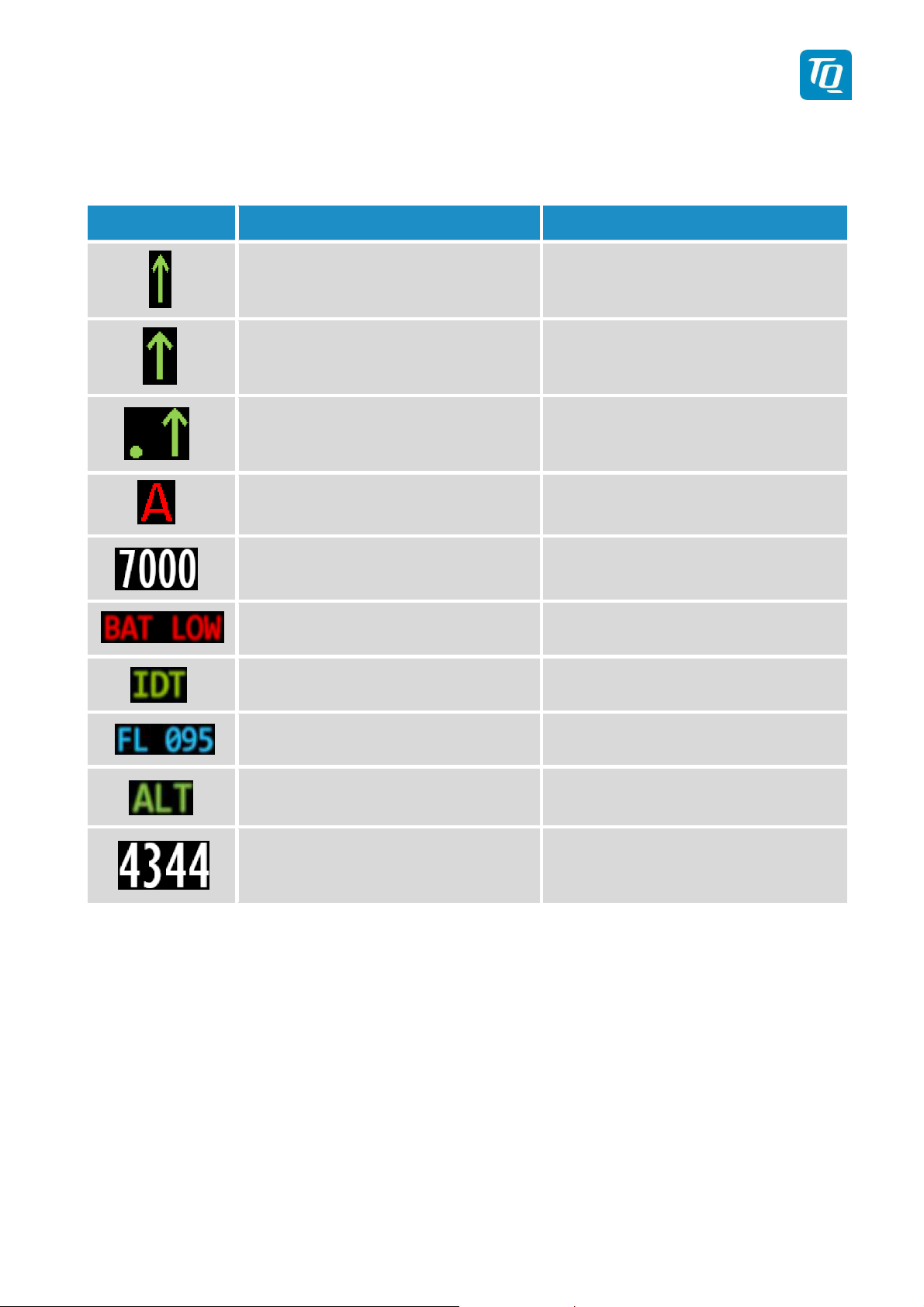
Indication Meaning Remark
Transponder is transmitting
Mode-A/C
Replies on Inter-
rogations
Appears per reply
Transponder is transmitting
Mode-S
Replies on Inter-
rogations
Appears per reply
Transponder is locked by
a ground station and will
be directly addressed
Appears at every addressed reply
Extended Squitter Status of Extended Squitter trans-
mission
Active Squawk
Battery power too low Blinking
Transmits IDENT- Marking ID („Squawk Ident“) has been
pressed – active for 18s
Flight Level Flight Level (in 100ft steps)
Mode display
(STBY, ON, GND, ALT)
see chapter. 2.1.6 Transponder-
Modes
Standby-Squawk
Can be changed with active
Squawk by pushing the UP/DOWN
(toggle) button
Figure 3: Indicators
TQ Aviation KTX2.0300
EASA.AP445 MAN
KTX2.A-MAN.0202.en.docx Page 14 of 49
© TQ-Systems GmbH. All information contained in this documents have to be treated strictly confidential. The transfer of presentations and know-how to third parties
requires the prior written consent of TQ-Systems GmbH.
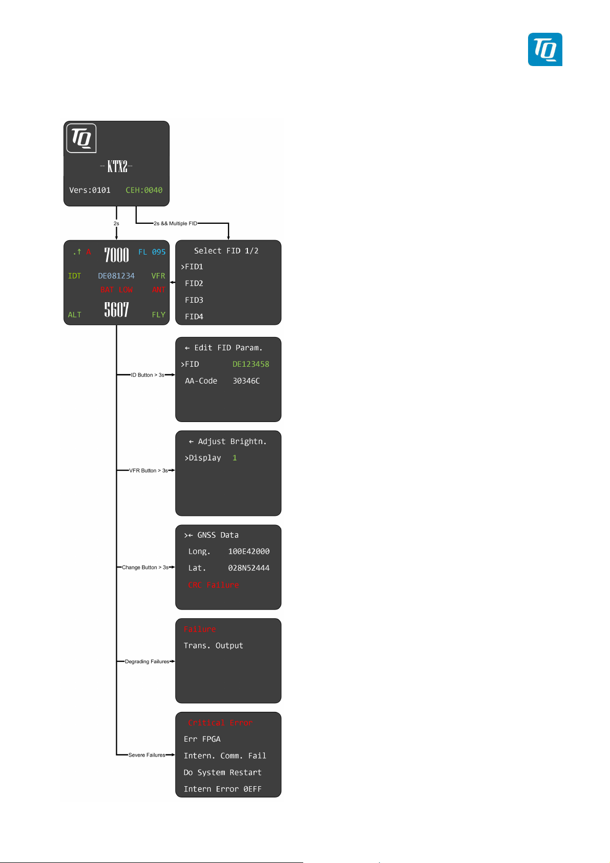
2.1.3.
Operation
menu structure
Figure 4: Operational menu structure
TQ Aviation KTX2.0300
EASA.AP445 MAN
KTX2.A-MAN.0202.en.docx Page 15 of 49
© TQ-Systems GmbH. All information contained in this documents have to be treated strictly confidential. The transfer of presentations and know-how to third parties
requires the prior written consent of TQ-Systems GmbH.
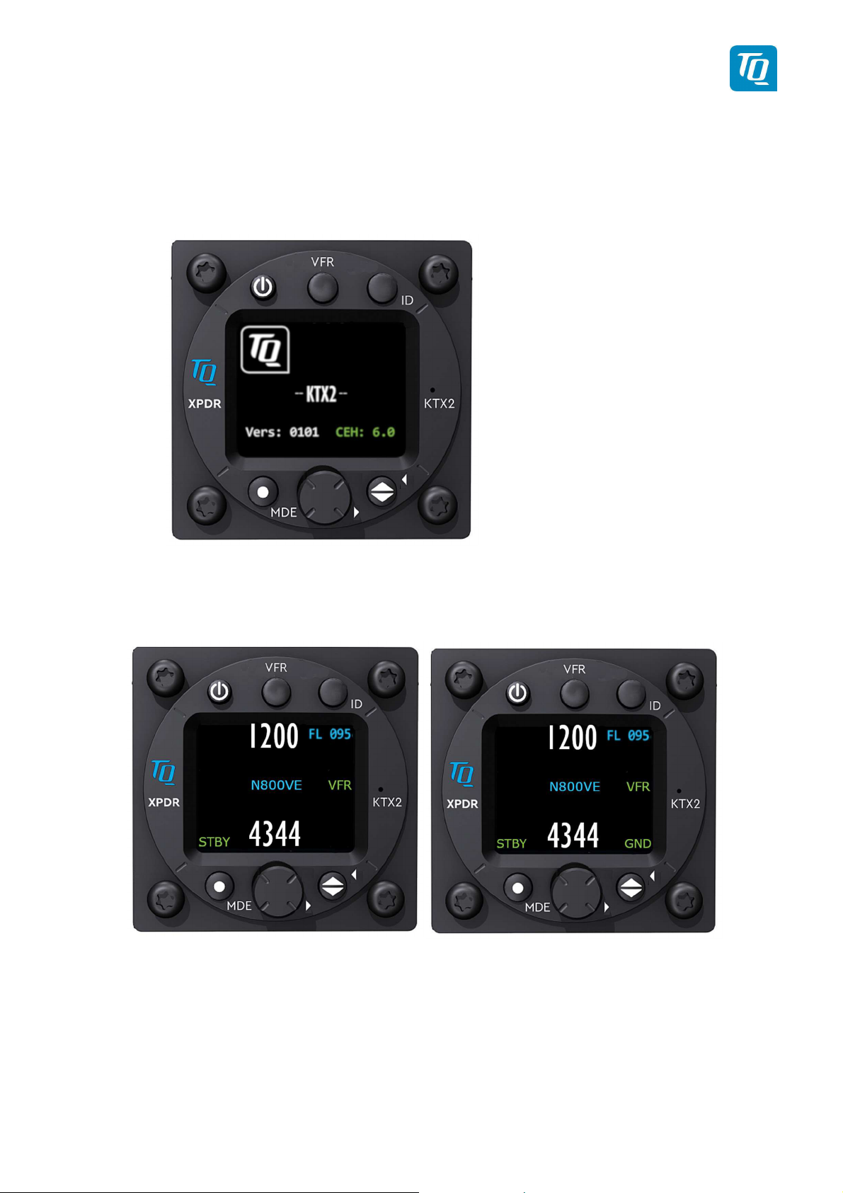
2.1.4. ON/OFF
The device is switched on/off by pushing the mechanically locked key. After power
up, the display appears as follows (example):
Device Name
-- KTX2 --
Software-Version
e.g. V.0101
Firmware-Version
e.g. FPGA: 6.0
After approx. 2 seconds the normal operation window appears and the transpond-
er will enter the mode ALT. If a weight on wheels switch is installed and the aircraft
is on ground the mode GND will be set.
No GND switch installed GND-switch installed, on GND
TQ Aviation KTX2.0300
EASA.AP445 MAN
KTX2.A-MAN.0202.en.docx Page 16 of 49
© TQ-Systems GmbH. All information contained in this documents have to be treated strictly confidential. The transfer of presentations and know-how to third parties
requires the prior written consent of TQ-Systems GmbH.
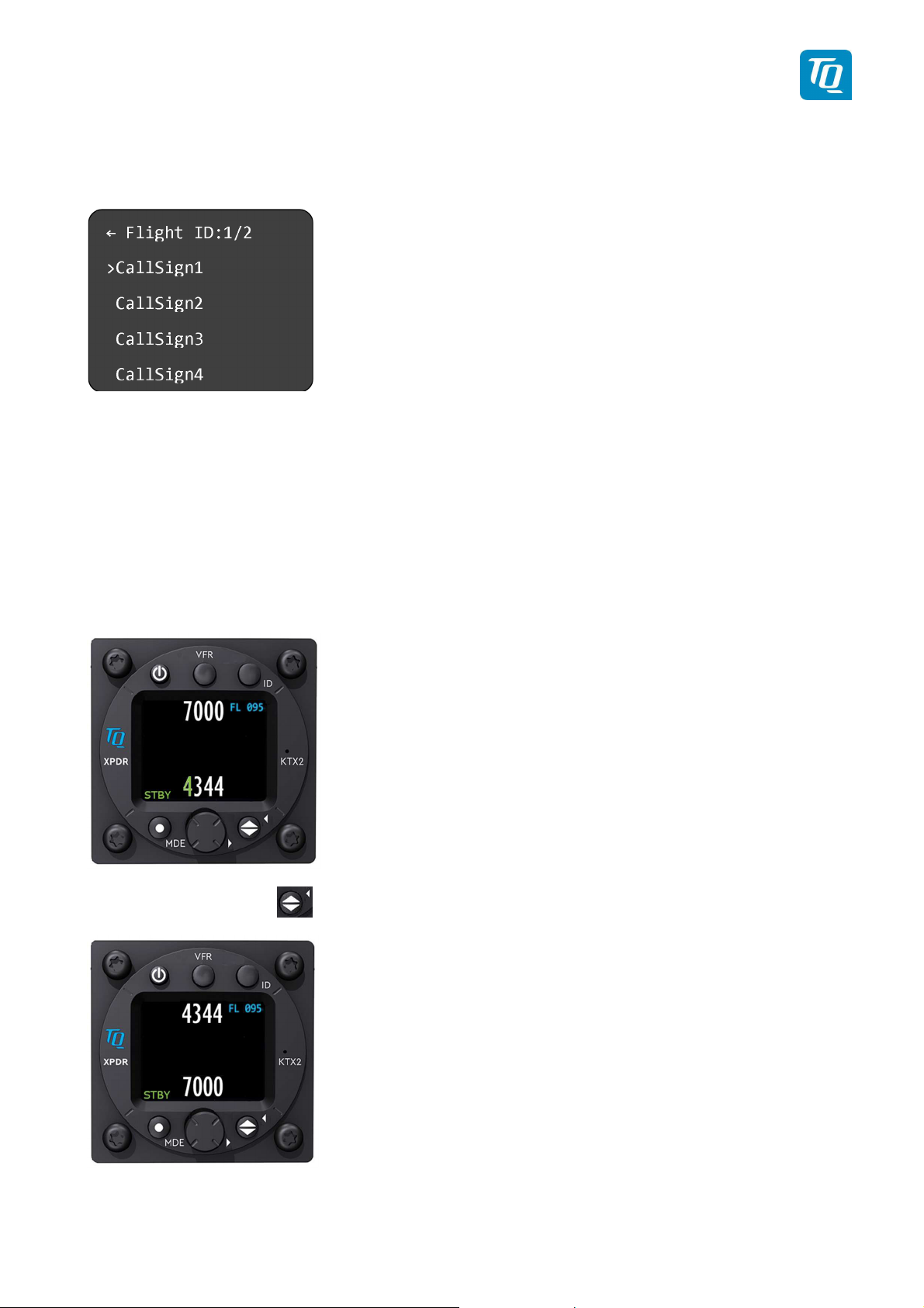
In case that multiple Flight ID’s are present, the screen will first display the selection menu for
one of the Flight ID’s:
Select the correct Flight ID by rotating the rotary knob to the one you chose and confirm by
pushing. The screen will switch automatically to the normal operation window.
2.1.5. Adjusting the Squawk
When pushing the rotating knob in the normal operating mode, the first number of the stand-
by squawk turns green, and can be adjusted by rotating the rotary knob. Pushing the rotary
knob will save the selected number and jump to the next digit which also will turn green dur-
ing adjustment.
Continue with the remaining numbers in this way until the desired squawk is set.
With the toggle button you can turn the stand-by squawk into the active squawk.
The active squawk is always on the top line.

TQ Aviation KTX2.0300
EASA.AP445 MAN
KTX2.A-MAN.0202.en.docx Page 17 of 49
© TQ-Systems GmbH. All information contained in this documents have to be treated strictly confidential. The transfer of presentations and know-how to third parties
requires the prior written consent of TQ-Systems GmbH.
2.1.6. Transponder-
Modes
The active mode is displayed at the bottom left corner.
STBY Transponder is
on
but
does not
respond to any interrogation.
GND Transponder responds to Mode-S interrogations.
ON Transponder responds to all interrogations, only altitude is not transmit-
ted.
ALT Transponder responds to all interrogations.
During the flight the Mode ALT should always be set, unless the air traffic control gives other
instructions.
While rolling on the ground the transponder should be set to GND, unless the installation in-
cludes a weight on wheels switch. In this case, the mode changes automatically.
The Mode-selection is done by (repeatedly) pushing the MDE button.
To enable or disable the Extended Squitter, press the MDE button for more than 3 seconds.
2.1.7. VFR –
Squawk
The factory setting of the VFR transponder code is 7000. The VFR transponder code howev-
er can be defined in accordance with local requirements, see setup menu chapter 3.1.5.
To activate the VFR-Squawk push the VFR button. VFR is then indicated on the display as
the active squawk.

TQ Aviation KTX2.0300
EASA.AP445 MAN
KTX2.A-MAN.0202.en.docx Page 18 of 49
© TQ-Systems GmbH. All information contained in this documents have to be treated strictly confidential. The transfer of presentations and know-how to third parties
requires the prior written consent of TQ-Systems GmbH.
2.1.8.
Squawk
Ident
(ID, SPI)
On request of the air traffic control, push the ID button (when not in the STBY mode).
Transmission of the ID signal will last for 18 seconds and “IDT” is displayed above the
mode and left side of the Flight ID.
2.1.9.
Flight
/
Ground
Indication
Aircrafts with AIR/GROUND switches display “FLY” (Flight) or “GND” (Ground) in the
lower right corner.
This function must be activated in the set-up procedure (see chap. 3.1.4.2).
When this function is not activated, there are no indications on the display and modes
must be manually selected in accordance with chapter 2.1.6.

TQ Aviation KTX2.0300
EASA.AP445 MAN
KTX2.A-MAN.0202.en.docx Page 19 of 49
© TQ-Systems GmbH. All information contained in this documents have to be treated strictly confidential. The transfer of presentations and know-how to third parties
requires the prior written consent of TQ-Systems GmbH.
2.2.
Adjustable
parameters in operation mode
2.2.1.
Flight
ID
To modify the Flight ID during operation, push the ID button for at least 3 seconds.
The parameters can be adjusted in the same way like described in chapter 3.1.2.
2.2.2. Flight ID
To modify the display brightness during operation, push the VFR button for at least 3 sec-
onds.
The menu appears, brightness can be adjusted by turning and pushing the rotary knob in the
same way as described in setup menu (see chap. 2.1.1).
TQ Aviation KTX2.0300
EASA.AP445 MAN
KTX2.A-MAN.0202.en.docx Page 20 of 49
© TQ-Systems GmbH. All information contained in this documents have to be treated strictly confidential. The transfer of presentations and know-how to third parties
requires the prior written consent of TQ-Systems GmbH.
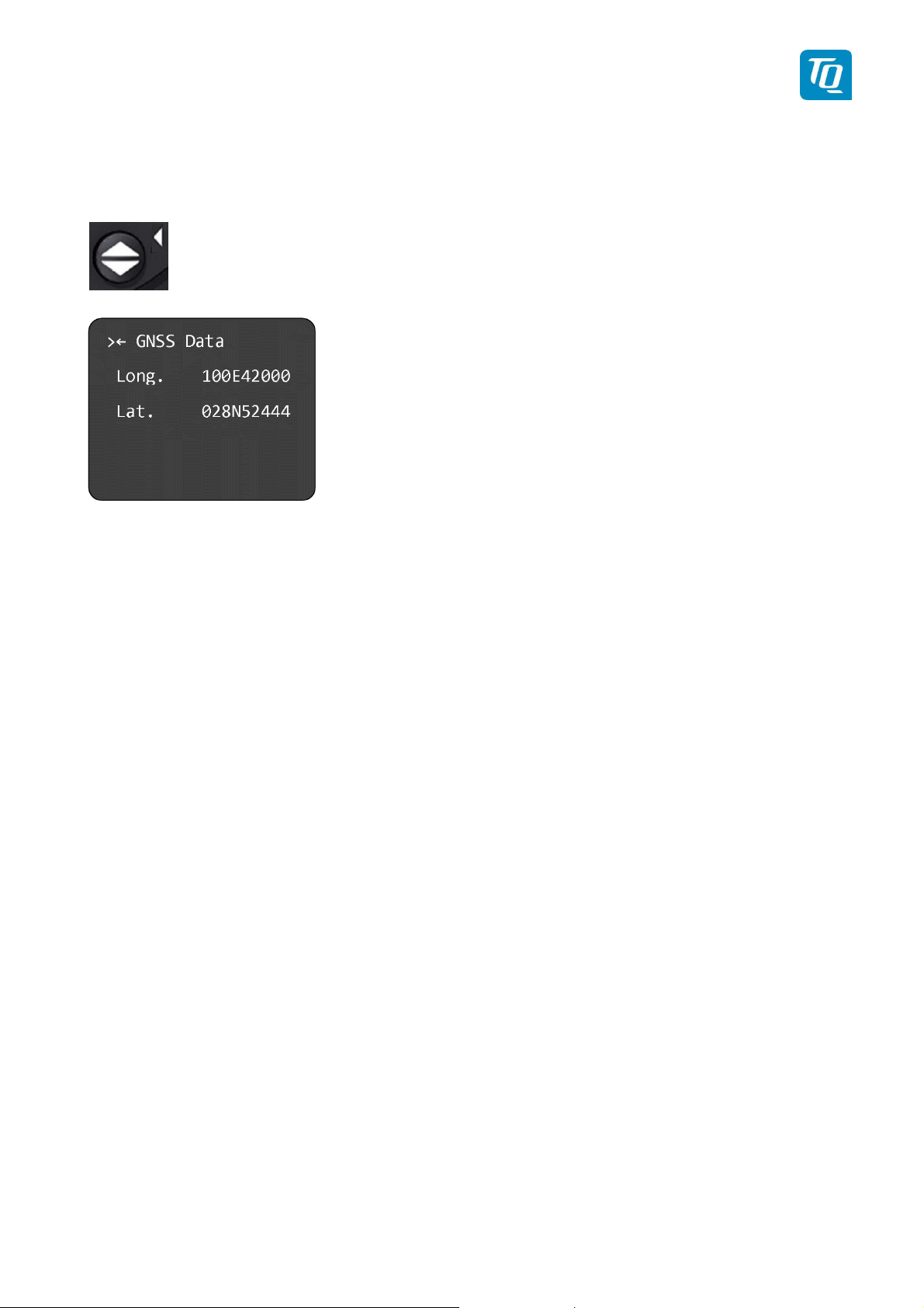
2.2.3. GNSS Data
The actual GNSS data can be displayed when pushing the toggle button for at least 3 sec-
onds:
TQ Aviation KTX2.0300
EASA.AP445 MAN
KTX2.A-MAN.0202.en.docx Page 21 of 49
© TQ-Systems GmbH. All information contained in this documents have to be treated strictly confidential. The transfer of presentations and know-how to third parties
requires the prior written consent of TQ-Systems GmbH.
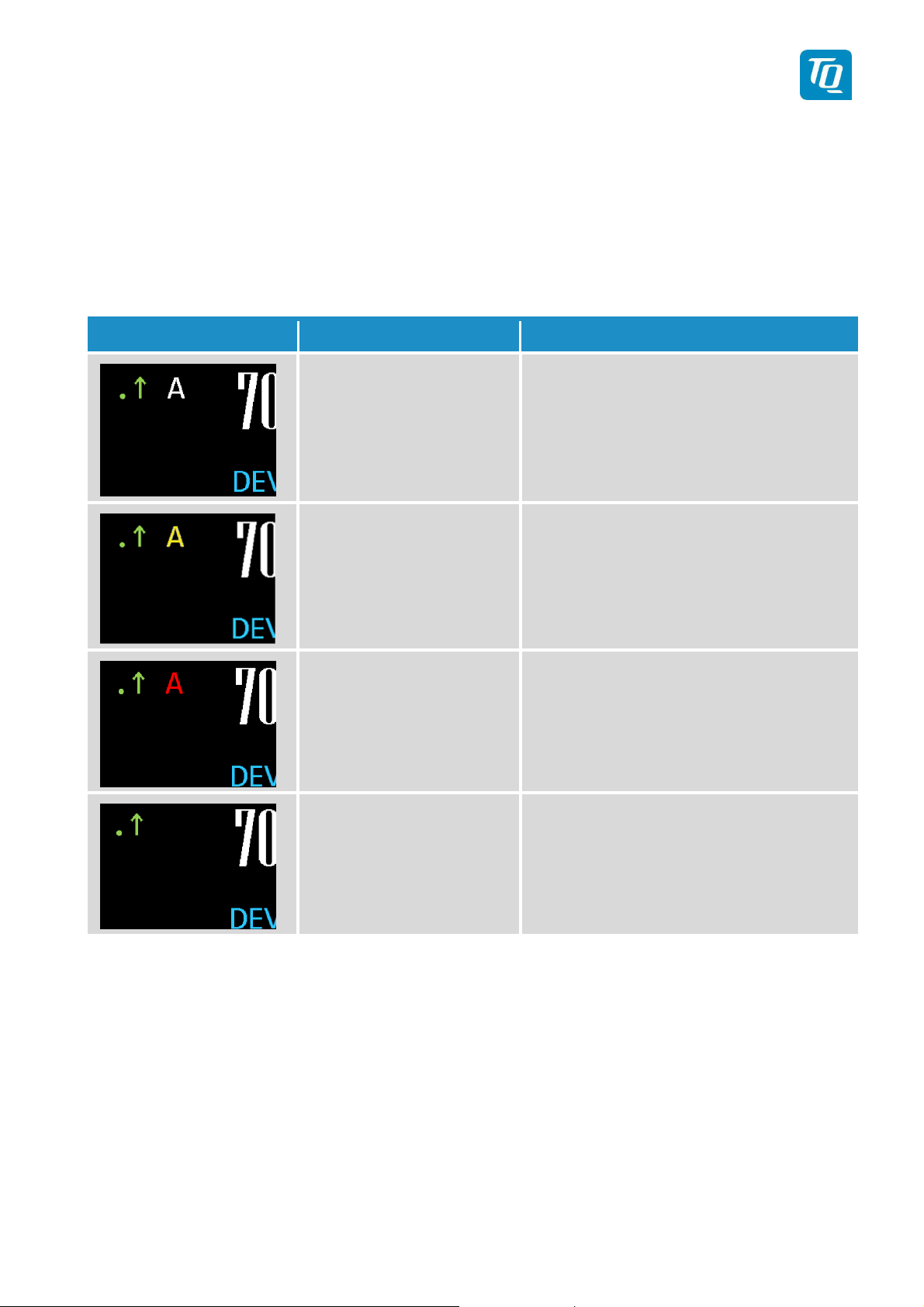
2.2.4.
Extended
Squitter
The Symbols for Extended Squitter show the current operational status of ES transmission:
Indication Function Description
Extended Squitter on.
Letter “A” appears white
ADS-B out function is active and
transmitting messages
Extended Squitter on.
Letter “A” appears yellow
ADS-B out function is active but not
transmitting messages
Extended Squitter on
Letter “A” appears red
ADS-B out function is active and
transmitting type ZERO position mes-
sages or no position messages due to
missing position data (longitude, alti-
tude, latitude)
Extended Squitter off
Letter “A” disappears No transmitting data
Figure 5: Extended Squitter
Other manuals for KTX2
2
This manual suits for next models
1
Table of contents
Other TQ Marine Radio manuals


Popular Marine Radio manuals by other brands

Mylaps
Mylaps RC4 PRO quick start guide

NorthStar
NorthStar VHF Marine Explorer 721EU Operation and installation manual

Kenwood
Kenwood TK-190 Service manual

Marine Audio
Marine Audio MA300BK Installation and operation manual

Furuno
Furuno FM-8900S Specifications

Cobra Marine
Cobra Marine MR F80B owner's manual


Simons Voss Technologies
Simons Voss Technologies ALLEGION 3060 Series quick guide

Raveon
Raveon RV-M7 GX WX quick start guide

EnerSys
EnerSys Alpha AlphaNet DOCSIS DM3X Series Technical manual

Garmin
Garmin GTX 45R installation manual

Garmin
Garmin VHF100 - 25W VHF RADIO Declaration of conformity

Himunication
Himunication HM380 Series user manual