TQ TQMx50UC User manual

User's Manual l TQMx50UC UM 0101 l © 2018 TQ-Group Page i
TQMx50UC
User's Manual
TQMx50UC UM 0101
2018-09-26

User's Manual l TQMx50UC UM 0101 l © 2018 TQ-Group Page i
TA LE OF CONTENTS
1. A OUT THIS MANUAL................................................................................................................................................................................1
1.1 Copyright and License Expenses............................................................................................................................................................1
1.2 Registered Trademarks..............................................................................................................................................................................1
1.3 Disclaimer......................................................................................................................................................................................................1
1.4 Imprint............................................................................................................................................................................................................1
1.5 Service and Support...................................................................................................................................................................................1
1.6 Tips on Safety ...............................................................................................................................................................................................2
1.7 Symbols and Typographic Conventions..............................................................................................................................................2
1.8 Handling and ESD Tips ..............................................................................................................................................................................2
1.9 Naming of Signals.......................................................................................................................................................................................3
1.10 Further Applicable Documents / Presumed Knowledge................................................................................................................3
2. INTRODUCTION ...........................................................................................................................................................................................4
2.1 Functional Overview..................................................................................................................................................................................4
2.2 Specification Compliance.........................................................................................................................................................................5
2.3 Versions..........................................................................................................................................................................................................5
2.4 Accessories....................................................................................................................................................................................................5
3. FUNCTIONAL SPECIFICATION..................................................................................................................................................................6
3.1 lock Diagram..............................................................................................................................................................................................6
3.2 Electrical Specification...............................................................................................................................................................................6
3.2.1 Supply Voltage Characteristics ...............................................................................................................................................................6
3.2.2 Power Consumption Specification........................................................................................................................................................7
3.2.3 Real Time Clock Current Specification..................................................................................................................................................7
3.3 Environmental Specification ...................................................................................................................................................................8
3.4 System Components..................................................................................................................................................................................8
3.4.1 Processor .......................................................................................................................................................................................................8
3.4.1.1 Intel® Turbo oost Technology ..............................................................................................................................................................9
3.4.1.2 Intel® Configurable Thermal Design Power........................................................................................................................................9
3.4.2 Graphics .........................................................................................................................................................................................................9
3.4.3 Chipset............................................................................................................................................................................................................9
3.4.4 Memory....................................................................................................................................................................................................... 10
3.4.4.1 DDR3L SDRAM .......................................................................................................................................................................................... 10
3.4.4.2 SPI oot Flash............................................................................................................................................................................................ 10
3.4.4.3 EEPROM....................................................................................................................................................................................................... 10
3.4.5 Real Time Clock......................................................................................................................................................................................... 10
3.4.6 Trusted Platform Module....................................................................................................................................................................... 10
3.4.7 Hardware Monitor.................................................................................................................................................................................... 10
3.4.8 TQ Flexible I/O Configuration (TQ-flexiCFG).................................................................................................................................... 10
3.4.9 Ultra Deep Power State Green ECO-Off ............................................................................................................................................ 11
3.5 Interfaces .................................................................................................................................................................................................... 11
3.5.1 PCI Express ................................................................................................................................................................................................. 11
3.5.2 PCI Express Graphics (PEG).................................................................................................................................................................... 11
3.5.3 Gigabit Ethernet ....................................................................................................................................................................................... 11
3.5.4 Serial ATA.................................................................................................................................................................................................... 11
3.5.5 Digital Display Interface......................................................................................................................................................................... 11
3.5.6 LVDS Interface........................................................................................................................................................................................... 11
3.5.7 US 2.0 Interfaces..................................................................................................................................................................................... 11
3.5.8 US 3.0 Interfaces..................................................................................................................................................................................... 12
3.5.9 General Purpose Input / Output.......................................................................................................................................................... 12
3.5.10 High Definition Audio Interface........................................................................................................................................................... 12
3.5.11 LPC us........................................................................................................................................................................................................ 12
3.5.12 IC us.......................................................................................................................................................................................................... 12
3.5.13 SM us .......................................................................................................................................................................................................... 12
3.5.14 Serial Peripheral Interface ..................................................................................................................................................................... 12
3.5.15 Serial Ports.................................................................................................................................................................................................. 13
3.5.16 Watchdog Timer....................................................................................................................................................................................... 13

User's Manual l TQMx50UC UM 0101 l © 2018 TQ-Group Page ii
TA LE OF CONTENTS (continued)
3.6 Connectors................................................................................................................................................................................................. 14
3.6.1 COM Express™ Connector ..................................................................................................................................................................... 14
3.6.2 Debug Header........................................................................................................................................................................................... 14
3.6.3 Debug Module LED ................................................................................................................................................................................. 14
3.7 COM Express™ Connector Pinout List................................................................................................................................................ 14
3.7.1 Signal Assignment Abbreviations....................................................................................................................................................... 14
3.7.2 COM Express™ Connector Pin Assignment...................................................................................................................................... 15
4. MECHANICS ............................................................................................................................................................................................... 23
4.1 TQMx50UC Dimensions ......................................................................................................................................................................... 23
4.2 Heat Spreader Dimensions ................................................................................................................................................................... 24
4.3 Mechanical and Thermal Aspects ....................................................................................................................................................... 24
4.4 Protection Against External Effects .................................................................................................................................................... 24
5. SOFTWARE.................................................................................................................................................................................................. 25
5.1 System Resources .................................................................................................................................................................................... 25
5.1.1 IC us.......................................................................................................................................................................................................... 25
5.1.2 SM us .......................................................................................................................................................................................................... 25
5.1.3 Memory Map ............................................................................................................................................................................................. 25
5.1.4 IRQ Map....................................................................................................................................................................................................... 25
5.2 Operating Systems .................................................................................................................................................................................. 26
5.2.1 Supported Operating Systems............................................................................................................................................................. 26
5.2.2 Driver Download...................................................................................................................................................................................... 26
5.3 IOS.............................................................................................................................................................................................................. 26
5.3.1 Enter IOS Setup ...................................................................................................................................................................................... 26
5.4 Software Tools........................................................................................................................................................................................... 26
6. SAFETY REQUIREMENTS AND PROTECTIVE REGULATIONS......................................................................................................... 27
6.1 EMC............................................................................................................................................................................................................... 27
6.2 ESD................................................................................................................................................................................................................ 27
6.3 Shock & Vibration..................................................................................................................................................................................... 27
6.4 Operational Safety and Personal Security........................................................................................................................................ 27
6.5 Reliability and Service Life..................................................................................................................................................................... 27
7. ENVIRONMENT PROTECTION................................................................................................................................................................ 28
7.1 RoHS............................................................................................................................................................................................................. 28
7.2 WEEE®.......................................................................................................................................................................................................... 28
7.3 REACH®........................................................................................................................................................................................................ 28
7.4 EUP................................................................................................................................................................................................................ 28
7.5 attery ......................................................................................................................................................................................................... 28
7.6 Packaging................................................................................................................................................................................................... 28
7.7 Other Entries.............................................................................................................................................................................................. 28
8. APPENDIX ................................................................................................................................................................................................... 29
8.1 Acronyms and Definitions..................................................................................................................................................................... 29
8.2 References.................................................................................................................................................................................................. 31

User's Manual l TQMx50UC UM 0101 l © 2018 TQ-Group Page iii
TA LE DIRECTORY
Table 1: Terms and Conventions.....................................................................................................................................................................2
Table 2: TQMx50UC Power Consumption....................................................................................................................................................7
Table 3: RTC Current Consumption................................................................................................................................................................7
Table 4: Processor Specifications....................................................................................................................................................................8
Table 5: Maximum Resolution in Dual Display Configuration...............................................................................................................9
Table 6: US 3.0 COM Express™ Port Mapping........................................................................................................................................ 12
Table 7: Serial Port COM Express™ Port Mapping................................................................................................................................... 13
Table 8: LED boot messages.......................................................................................................................................................................... 14
Table 9: Signal Assignment Abbreviations ............................................................................................................................................... 14
Table 10: COM Express™ Connector Pin Assignment .............................................................................................................................. 15
Table 11: IC address mapping COM Express™ IC port........................................................................................................................... 25
Table 12: IC address mapping COM Express™ SM us port................................................................................................................... 25
Table 13: Acronyms ............................................................................................................................................................................................ 29
Table 14: Further Applicable Documents and Links................................................................................................................................. 31
ILLUSTRATION DIRECTORY
Illustration 1: lock Diagram TQMx50UC................................................................................................................................................................6
Illustration 2: Three view drawing TQMx50UC .................................................................................................................................................. 23
Illustration 3: ottom view drawing TQMx50UC............................................................................................................................................... 23
Illustration 4: Standard Heat Spreader “TQMx50UC-HSP”.............................................................................................................................. 24
REVISION HISTORY
Rev. Date Name Pos. Modification
0100 2015-12-16 FP First edition
0101 2017-07-04 FP
All
3.5.1, 3.5.2
3.7.2
6.5.2
Typo
Information clarified
Errors corrected
Updated
0102 2018-09-26 FP
2.1
3.4.4.3
3.5.1, 3.5.2
7
“Memory”: Type of EEPROM corrected
“Peripheral interfaces”: PCIe lane assignment clarified;
Size and type of EEPROM corrected
PCIe lane assignment clarified
Reworked

User's Manual l TQMx50UC UM 0101 l © 2018 TQ-Group Page 1
1. ABOUT THIS MANUAL
1.1 Copyright and License Expenses
Copyright protected © 2018 by TQ-Systems GmbH.
This User's Manual may not be copied, reproduced, translated, changed or distributed, completely or partially in electronic,
machine readable, or in any other form without the written consent of TQ-Systems GmbH.
The drivers and utilities for the components used as well as the IOS are subject to copyrights of the respective manufacturers.
The licence conditions of the respective manufacturer are to be adhered to.
IOS-licence expenses are paid by TQ-Systems GmbH and are included in the price.
Licence expenses for the operating system and applications are not taken into consideration and have to be calculated /
declared separately.
1. Registered Trademarks
TQ-Systems GmbH aims to adhere to copyrights of all graphics and texts used in all publications, and strives to use original
or license-free graphics and texts.
All brand names and trademarks mentioned in the publication, including those protected by a third party, unless specified
otherwise in writing, are subjected to the specifications of the current copyright laws and the proprietary laws of the present
registered proprietor without any limitation. One should conclude that brand and trademarks are rightly protected by a third
party.
1.3 Disclaimer
TQ-Systems GmbH does not guarantee that the information in this User's Manual is up-to-date, correct, complete or of good
quality. Nor does TQ-Systems GmbH assume guarantee for further usage of the information. Liability claims against TQ-Systems
GmbH, referring to material or non-material related damages caused, due to usage or non-usage of the information given in the
User's Manual, or due to usage of erroneous or incomplete information, are exempted, as long as there is no proven intentional
or negligent fault of TQ-Systems GmbH.
TQ-Systems GmbH explicitly reserves the rights to change or add to the contents of this User's Manual or parts of it without
special notification.
1.4 Imprint
TQ-Systems GmbH
Gut Delling, Mühlstraße 2
D-8 9 Seefeld
Tel: +49 8153 9308–0
Fax: +49 8153 9308–4223
Web: TQ-Group
1.5 Service and Support
Please visit our website TQ-Group for latest product documentation, drivers, utilities and technical support.
You can register on our website TQ-Group to have access to restricted information and automatic update services.
For direct technical support you can contact our FAE team by email: TQ-Support.
Our FAE team can also support you with additional information like 3D-STEP files and confidential information, which is not
provided on our public website.
For service/RMA, please contact our service team by email (TQ-Service) or your sales team at TQ-Systems GmbH.

User's Manual l TQMx50UC UM 0101 l © 2018 TQ-Group Page 2
1.6 Tips on Safety
Improper or incorrect handling of the product can substantially reduce its life span.
1.7 Symbols and Typographic Conventions
Table 1: Terms and Conventions
Symbol Meaning
This symbol represents the handling of electrostatic-sensitive modules and / or components. These
components are often damaged / destroyed by the transmission of a voltage higher than about 50 V.
A human body usually only experiences electrostatic discharges above approximately 3,000 V.
This symbol indicates the possible use of voltages higher than 24 V.
Please note the relevant statutory regulations in this regard.
Non-compliance with these regulations can lead to serious damage to your health and also cause
damage / destruction of the component.
This symbol indicates a possible source of danger. Acting against the procedure described can lead to
possible damage to your health and / or cause damage / destruction of the material used.
This symbol represents important details or aspects for working with TQ-products.
Command A font with fixed-width is used to denote commands, contents, file names, or menu items.
1.8 Handling and ESD Tips
General handling of your TQ-products
The TQ-product may only be used and serviced by certified personnel who have taken note of the
information, the safety regulations in this document and all related rules and regulations.
A general rule is: do not touch the TQ-product during operation. This is especially important when
switching on, changing jumper settings or connecting other devices without ensuring beforehand
that the power supply of the system has been switched off.
Violation of this guideline may result in damage / destruction of the TQMx50UC and be dangerous to
your health.
Improper handling of your TQ-product would render the guarantee invalid.
Proper ESD handling
The electronic components of your TQ-product are sensitive to electrostatic discharge (ESD).
Always wear antistatic clothing, use ESD-safe tools, packing materials etc., and operate your TQ-
product in an ESD-safe environment. Especially when you switch modules on, change jumper settings,
or connect other devices.

User's Manual l TQMx50UC UM 0101 l © 2018 TQ-Group Page 3
1.9 Naming of Signals
A hash mark (#) at the end of the signal name indicates a low-active signal.
Example: RESET#
If a signal can switch between two functions and if this is noted in the name of the signal, the low-active function is marked
with a hash mark and shown at the end.
Example: C / D#
If a signal has multiple functions, the individual functions are separated by slashes when they are important for the wiring.
The identification of the individual functions follows the above conventions.
Example: WE2# / OE#
1.10 Further Applicable Documents / Presumed Knowledge
•Specifications and manual of the modules used:
These documents describe the service, functionality and special characteristics of the module used.
•Specifications of the components used:
The manufacturer's specifications of the components used, for example CompactFlash cards, are to be taken note of.
They contain, if applicable, additional information that must be taken note of for safe and reliable operation.
These documents are stored at TQ-Systems GmbH.
•Chip errata:
It is the user's responsibility to make sure all errata published by the manufacturer of each component are taken note of.
The manufacturer’s advice should be followed.
•Software behaviour:
No warranty can be given, nor responsibility taken for any unexpected software behaviour due to deficient components.
•General expertise:
Expertise in electrical engineering / computer engineering is required for the installation and the use of the device.
Implementation information for the carrier board design is provided in the COM Express™ Design Guide (5) maintained by the
PICMG®. This Carrier Design Guide includes a very good guideline to design a COM Express™ carrier board.
It includes detailed information with schematics and detailed layout guidelines.
Further information can be found in the official PICMG® documentation (4).

User's Manual l TQMx50UC UM 0101 l © 2018 TQ-Group Page 4
. INTRODUCTION
ased on the internationally established PICMG® standard COM Express™ (COM.0 R2.1), Compact, the TQMx50UC enables the
design of not only powerful but also economical x86 based systems. The user has access to all essential interfaces of the CPU at
the Type 6 compliant pin out connector. Hence all features of the 5th Generation Intel® Core™ processor can be used. The direct
access to all interfaces gives the user the freedom to use the features of the CPU in the most suitable way for his application.
The compact and robust design as well as the option of conformal coating extends the use cases to applications within rugged
industry, railway and aviation environments. ased on the very low-power consumption and the extended temperature support
it is also possible to realize outdoor applications in an easy and reliable way.
.1 Functional Overview
The following key functions are implemented on the TQMx50UC:
Processor:
•5th Generation Intel® Core™ 5000U series (“ roadwell-U”)
•Intel® Core™ i7-5650U: 2 × 2.2 GHz / 3.2 GHz Turbo, 4 M Cache, HD6000
•Intel® Core™ i5-5350U: 2 × 1.8 GHz / 2.9 GHz Turbo, 3 M Cache, HD6000
•Intel® Core™ i3-5010U: 2 × 2.1 GHz, 3 M Cache, HD5500
•Intel® Celeron® 3765U: 2 × 1.7 GHz, 2 M Cache, HD
•Hyper-Threading and Virtualization support
•15 W TDP max. (configurable down to 9.5 / 10 W)
Memory:
•DDR3L-1600 dual channel: 4 Gbyte and 8 Gbyte memory down configuration
•EEPROM: 32 kbit (24AA32)
Graphics:
•Three independent display outputs:
•2 × Digital Display Interface / DP++ with up to 4K; DisplayPort 1.2a with support for Multi-Stream Transport (MST)
•LVDS Interface (18/24 bit, single/dual channel); optional eDP 1.3 with 4 lanes
System interfaces:
•1 × Gigabit Ethernet (Intel® i218)
•2 × US 3.0 (with US 2.0 backward compatibility)
•8 × US 2.0 (incl. US 3.0 ports)
Peripheral interfaces:
•4 × SATA Gen3 (up to 6 Gb/s)
•4 × PCIe 2.0 (×1) (up to 5 Gb/s), (4 (×1), 2 (×2) or 1 (×4))
•4 × PCIe 2.0 PEG port (×1) (up to 5 Gb/s), (+1 additional PCIe 2.0 PEG port (×1), if no Ethernet)
•1 × LPC bus
•1 × Intel® HD audio (HDA)
•1 × IC, (2nd IC optional) (master/slave capable)
•1 × SM us
•1 × SPI (for external uEFI IOS flash)
•2 × Serial port (Rx/Tx, legacy compatible), 4-wire optional through TQ-flexiCFG
•8 × GPIO through TQ-flexiCFG
Security components:
•TPM (SL 9660 TPM 1.2, alternatively SL 9665 TPM 2.0)
Others:
•TQMx86 board controller with Watchdog and TQ-flexiCFG
•Industrial real time clock (iRTC) (option)
•Hardware monitor
Power supply:
•Voltage: 8.5 V to 20 V, 5 V Standby (optional)
3 V attery for RTC (GoldCap option with iRTC)
Environment:
•Standard Temperature: 0 °C to +60 °C
•Extended temperature: –40 °C to +85 °C (on request)
Form factor / dimensions:
•COM Express™ Compact, Type 6, 95 × 95 mm

User's Manual l TQMx50UC UM 0101 l © 2018 TQ-Group Page 5
. Specification Compliance
The TQMx50UC is compliant to the PICMG® COM Express™ Module ase Specification (COM.0 R2.1) Compact, Type 6,
95 × 95 mm.
.3 Versions
The TQMx50UC is available in several standard configurations.
•TQMx50UC-AC ("Premium")
Intel® Core™ i7-5650U (2 × 2.2 GHz / 3.2 GHz Turbo, 4 M Cache, HD6000 Gfx),
8G DDR3L-1600, TPM, Standard-Temp. 0 to +60 °C
•TQMx50UC-AB ("Mainstream")
Intel® Core™ i5-5350U (2 × 1.8 GHz / 2.9 GHz Turbo, 3 M Cache, HD6000 Gfx),
4G DDR3L-1600, TPM, Standard-Temp. 0 to +60 °C
•TQMx50UC-AA ("Entry Level")
Intel® Core™ i3-5010U (2 × 2.1 GHz, 3 M Cache, HD5500 Gfx),
4G DDR3L-1600, Standard-Temp. 0 to +60 °C
•TQMx50UC-AD ("Basic")
Intel® Celeron® 3765U (2 × 1.7 GHz, 2 M Cache, HD Gfx),
4G DDR3L-1600, Standard-Temp. 0 to +60 °C
Please visit to TQ-Group/TQMx50UC for a complete list of standard versions.
Other configurations are available on request.
Standard configuration features are:
•CPU version
•Memory configuration
•TPM
•Temperature range
Optional hardware and software configuration features:
•Conformal coating can be offered as a customer specific add-on
•Custom specific GPIO configuration through TQ-flexiCFG
•4 (×1) PCIe lanes on PCI Express PEG port
•LVDS / eDP configuration
•iRTC
•Custom specific IOS configuration
For further information regarding other versions, please contact TQ-Support.
.4 Accessories
•TQMx50UC-HSP (TQMx50UC-HSP-11-M-5083-BL)
Heat spreader for TQMx50UC according to the COM Express™ specification.
•Evaluation platform MB-COME6-1
Mainboard for COM Express™ Compact Modules, Type 6.
Interfaces: 2 × DP, LVDS, 2 × Gbit Ethernet, 4 × US , 3 × COM, audio, mini PCIe, mSATA, 2.5” SSD, SD card,
riser extension with PCIe and US , fan, debug.
Dimensions: 170 × 170 mm.
User's Manual l TQMx50UC UM 0101 l © 2018 TQ-Group Page 6
3. FUNCTIONAL SPECIFICATION
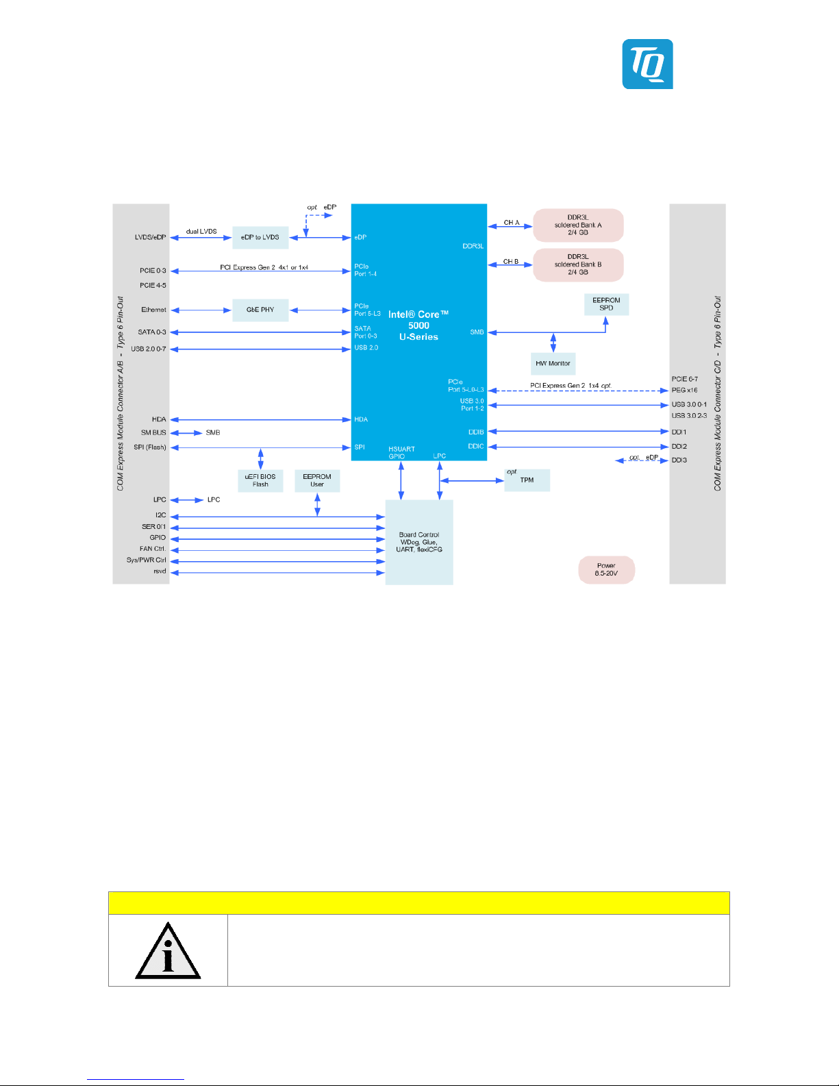
3.1 Block Diagram
The following illustration shows the block diagram of the TQMx50UC.
Illustration 1: lock Diagram TQMx50UC
3. Electrical Specification
3.2.1 Supply Voltage Characteristics
The TQMx50UC supports a wide-range voltage input from 8.5 V to 20 V.
The following supply voltages are specified at the COM Express™ connector:
Wide input: 8.5 V to 20 V maximum input ripple: ±100 mV
VCC_5V_S Y: 4.75 V to 5.25 V maximum input ripple: ±50 mV
VCC_RTC: 2.0 V to 3.3 V maximum input ripple: ±20 mV
The input voltages shall rise from 10 % of nominal to 90 % of nominal within 0.1 ms to 20 ms (0.1 ms ≤ Rise Time ≤ 20 ms).
There must be a smooth and continuous increase of each DC output voltage from 10 % to 90 % of its final set point within the
regulation range.
Note: Power source
For single supply operations, the 5 V Standby voltage is not required.
VCC_5V_S Y can be left open.

User's Manual l TQMx50UC UM 0101 l © 2018 TQ-Group Page 7
3.2.2 Power Consumption Specification
The power consumption values below show the voltage and power specifications of the TQMx50UC.
The values were measured with two power supplies; one for the TQMx50UC and the other one for the M -COME6-1 COM
Express™ carrier board.
The power consumption of each TQMx50UC was measured under Windows® 7, 64-bit.
All measurements were done at a temperature of +25 °C.
The power consumption of the TQMx50UC depends on the application, the mode of operation and the operating system.
The power consumption was measured under the following test modes:
•Windows® 7, 64-bit, idle state:
Desktop idle state, Ethernet port is disconnected.
•Windows® 7, 64-bit, maximum workload (cTDP down mode enabled)
These values show the maximum cTDP down power consumption using the Intel® stress test tool to stress the
processor and graphic engine. Ethernet port is connected (1,000 Mbps Speed).
•Windows® 7, 64-bit, maximum workload:
These values show the maximum worst case power consumption using the Intel® stress test tool to stress the processor
and graphic engine. Ethernet port is connected (1,000 Mbps Speed).
•Suspend mode:
The system is in S5/S4 state, Ethernet port is disconnected.
•Green ECO-Off state:
The system is in Green ECO-Off state, all DC/DC power supplies on the TQMx50UC are switched off.
The following table shows the power consumption with different processor configurations.
Table 2: TQMx50UC Power Consumption
Mode
Standby 5 V Wide input 12 V
TQMx50UC
Green ECO-Off state Suspend Win7, 64 bit
idle
Win7, 64 bit
cTDP down
max. load
Win7, 64 bit
max. load
i7-5650U with 4 / 8 Gbyte DDR3L (TQMx50UC-AC) 4.0 mW 190.0 mW 3.5 W 11.4 W 16.5 W
i5-5350U with 4 / 8 Gbyte DDR3L (TQMx50UC-A ) 4.0 mW 190.0 mW 3.5 W 11.4 W 16.5 W
i3-5010U with 4 / 8 Gbyte DDR3L (TQMx50UC-AA) 4.0 mW 190.0 mW 3.6 W 11.8 W 16.3 W
Celeron 3765U with 4 / 8 Gbyte DDR3L (TQMx50UC-AD) 4.0 mW 190.0 mW 3.6 W 11.9 W 16.3 W
Note: Power requirement
The power supplies on the carrier board for the TQMx50UC must be designed with enough reserve.
The carrier board should be able to provide at least twice the maximum workload power of the
TQMx50UC. The TQMx50UC supports several low-power states. The power supply of the carrier board
has to be stable even with no load.
3.2.3 Real Time Clock Current Specification
The RTC (VCC_RTC) current consumption is shown below.
The values were measured at +25 °C under battery operating conditions.
Table 3: RTC Current Consumption
Mode Voltage Current
5th Generation Intel® Core™ 5000U series integrated RTC 3.0 V 3 µA
With iRTC option 3.0 V 300 nA
The current consumption of the RTC in the 5th Generation Intel® Core™ 5000U series processor Product Family Datasheet is
specified with 6 µA in average, but the values measured on several TQMx50UC were lower.

User's Manual l TQMx50UC UM 0101 l © 2018 TQ-Group Page 8
3.3 Environmental Specification
•Temperature operating Standard: 0 °C to +60 °C
•Temperature operating Extended: –40 °C to +85 °C
•Temperature storage: –40 °C to +85 °C
•Relative humidity (operating / storage): 10 % to 90 % (not condensing)
Attention: Maximum operating temperature
Do not operate the TQMx50UC if it is not attached properly to a heat spreader and a heat sink!
3.4 System Components
3.4.1 Processor
The TQMx50UC supports the 5th Generation Intel® Core™ 5000U series.
The following list illustrates some key features of the 5th Generation Intel® Core™ 5000U series processor:
•Ultra low-power, maximum 15 W
•Single, dual processor cores
•Intel® Hyper-Threading Technology (Intel® HT Technology)
•Intel® Streaming SIMD Extensions 4.2 (Intel® SSE4.2)
•Intel® Advanced Vector Extensions 2.0 (Intel® AVX2)
•Intel® 64 Architecture
•Intel® Turbo oost Technology 2.0
•Intel® Configurable Thermal Design Power (Intel® cTDP)
•Intel® Enhanced Intel® SpeedStep® technology
•Up to 4 Mbyte cache
•Intel® HD Graphics
•Triple independent displays
Table 4: Processor Specifications
Mode i7-5650U i5-5350U i3-5010U Celeron-3765U
Processor Cores / Threads 2 / 4 2 / 4 2 / 4 2 / 2
Cache 4 Mbyte 3 Mbyte 3 Mbyte 2 Mbyte
Core ase frequency 2.2 GHz 1.8 GHz 2.1 GHz 1.7 GHz
Core Turbo Single Core frequency 3.2 GHz 2.9 GHz – –
Core Turbo Dual Core frequency 3.1 GHz 2.7 GHz – –
Temperature Tjunction 0 °C to +105 °C 0 °C to +105 °C 0 °C to +105 °C 0 °C to +105 °C
Memory speed 1,600 MT/s 1,600 MT/s 1,600 MT/s 1,600 MT/s
Max. memory 8 Gbyte 8 Gbyte 8 Gbyte 8 Gbyte
Memory configuration Dual, no ECC Dual, no ECC Dual, no ECC Dual, no ECC
Graphics Intel® HD Graphics
HD6000 (GT3)
Intel® HD Graphics
HD6000 (GT3)
Intel® HD Graphics
HD5500 (GT2)
Intel® HD Graphics
HD (GT1)
Graphics Execution Units 48 48 24 12
Graphics ase frequency 0.3 GHz 0.3 GHz 0.3 GHz 0.1 GHz
Graphics Turbo frequency 1.0 GHz 1.0 GHz 0.9 GHz 0.8 GHz
Thermal Design Power (TDP) 15 W 15 W 15 W 15 W
Configurable Thermal Design Power (cTDP) 9.5 W 9.5 W 10 W 10 W

User's Manual l TQMx50UC UM 0101 l © 2018 TQ-Group Page 9
3.4.1.1 Intel® Turbo oost Technology
Intel® Turbo oost Technology accelerates processor and graphics performance for peak loads, automatically allowing processor
cores to run faster than the rated operating frequency if they are operating below power, current, and temperature specification
limits. Whether the processor enters into Intel® Turbo oost Technology and the amount of time the processor spends in that
state depends on the workload and operating environment.
The Intel® Turbo oost Technology allows the processor to operate at a power level that is higher than its Thermal Design Power
(TDP) configuration for short durations to maximize performance.
The Intel® Turbo oost Technology can be configured in the uEFI IOS, the default setting is “enabled”.
Only the Intel® Core™ i7 and i5 processors support Intel® Turbo oost Technology.
3.4.1.2 Intel® Configurable Thermal Design Power
The Intel® Configurable Thermal Design Power (cTDP) feature allows adjustment of the processor power consumption.
The cTDP down mode specifies a lower processor power consumption and lower guaranteed frequency versus the nominal
mode. This mode can be selected for ultra low-power applications, e.g. systems with passive cooling solutions.
The cTDP can be configured in the uEFI IOS, the default setting is “nominal”.
3.4.2 Graphics
The 5th Generation Intel® Core™ 5000U processor series includes an integrated Intel® HD graphics accelerator. It provides
excellent 2D / 3D graphics performance with triple simultaneous display support.
The following list illustrates some key features of the 5th Generation Intel® Core™ 5000U series processor:
•Graphics Technology GT3 with 48 Execution Units (HD6000)
•Graphics Technology GT2 with 24 Execution Units (HD5500)
•Graphics Technology GT1 with 12 Execution Units (HD)
•DirectX* 11.1, DirectX* 11.1+, DirectX* 11, DirectX* 10.1, DirectX* 10, DirectX* 9 support
•OpenGL* 4.0, OpenGL* 4.2 support
The TQMx50UC supports two Digital Display Interfaces (DDI0 and DDI1) and one dual LVDS interface at the COM Express™
connector.
Table 5: Maximum Resolution in Dual Display Configuration
Display 1 Display 2 Display 3 Display 1
Max. resolution
Display 2
Max. resolution
Display 3
Max. resolution
HDMI HDMI dual LVDS 4096 × 2304 @ 24 Hz 4096 × 2304 @ 24 Hz 1920 × 1200 @ 60 Hz
HDMI DP dual LVDS 4096 × 2304 @ 24 Hz 3840 × 2160 @ 60 Hz 1920 × 1200 @ 60 Hz
DP DP dual LVDS 3840 × 2160 @ 60 Hz 3840 × 2160 @ 60 Hz 1920 × 1200 @ 60 Hz
HDMI HDMI eDP 4096 × 2304 @ 24 Hz 4096 × 2304 @ 24 Hz 3840 × 2160 @ 60 Hz
HDMI DP eDP 4096 × 2304 @ 24 Hz 3840 × 2160 @ 60 Hz 3840 × 2160 @ 60 Hz
DP DP eDP 3840 × 2160 @ 60 Hz 3840 × 2160 @ 60 Hz 3840 × 2160 @ 60 Hz
3.4.3 Chipset
The TQMx50UC provides the Intel® 9 Series PCH-LP integrated in the Multi-Chip package.

User's Manual l TQMx50UC UM 0101 l © 2018 TQ-Group Page 10
3.4.4 Memory
3.4.4.1 DDR3L SDRAM
The TQMx50UC supports a memory-down dual-channel DDR3L configuration without error-correcting code (ECC), running at
up to 1600 MT/s. The maximum memory size is 8 Gbyte. The available memory configuration can be either 4 Gbyte or 8 Gbyte.
3.4.4.2 SPI oot Flash
The TQMx50UC provides a 128 Mbit SPI boot flash. It includes the Intel® Management Engine (Intel® ME) and the uEFI IOS. An
external SPI boot flash can be used instead of the on-board SPI boot flash. The uEFI IOS supports the following 3.3 V SPI flash
devices on the carrier board:
•Winbond W25Q128FV
•Macronix MX25L12835F
3.4.4.3 EEPROM
The TQMx50UC provides an EEPROM. The 32 kbit (24AA32) EEPROM is connected to the general purpose IC interface
(COM Express™ pins I2C_DAT and I2C_CK).
3.4.5 Real Time Clock
The TQMx50UC provides a standard RTC (Motorola MC146818 ) integrated in the 5th Generation Intel® Core™ 5000U processor
series and a high accuracy, ultra-low-power industrial RTC (iRTC) as an assembly option.
The following list illustrates some key features of the iRTC:
•Lowest current consumption (typ. 240 nA)
•Optimized for GoldCap® capacitor backup
•Temperature compensation: –40 °C to +85 °C
•Time deviation ±0.26 s/day / ±3.0 ppm
•Time keeping voltage down to 1.5 V
Please contact TQ-Support for further information about the iRTC.
3.4.6 Trusted Platform Module
The TQMx50UC has been designed to support the Trusted Platform Module (TPM) 1.2 (Infineon SL 9660).
The TPM 2.0 configuration is available on request.
3.4.7 Hardware Monitor
The TQMx50UC provides an integrated Hardware Monitor to monitor the on-board and processor die temperature, board
voltages and manage the fan control of the COM Express™ interface (FAN_PWMOUT and FAN_TACHOIN).
3.4.8 TQ Flexible I/O Configuration (TQ-flexiCFG)
The TQMx50UC provides a flexible I/O configuration feature, TQ-flexiCFG.
Using the TQ-flexiCFG, several COM Express™ I/O interfaces and functions can be configured via a programmable FPGA.
This feature enables the user to integrate special embedded features and configuration options in the TQMx50UC to reduce
the carrier board design effort.
Here are some examples of the flexible I/O configuration:
•GPIO interrupt configuration
•Interrupt configuration via LPC Serial IRQ
•Serial port handshake signals via GPIOs
•Integrate additional I/O functions, e.g. additional Serial, CAN, IC, PWM controller or special power management
configurations
Please contact TQ-Support for further information about the TQ-flexiCFG.

User's Manual l TQMx50UC UM 0101 l © 2018 TQ-Group Page 11
3.4.9 Ultra Deep Power State Green ECO-Off
The TQMx50UC supports the ultra-deep power state Green ECO-Off. In this configuration all DC/DC power supplies on the
TQMx50UC are switched off. This results in lowest power consumption.
The Green ECO-Off mode can be configured in the uEFI IOS setup.
To wake up the system from the Green ECO-Off mode the power button signal must be pulled low for a minimum of 100 ms.
3.5 Interfaces
3.5.1 PCI Express
The TQMx50UC supports up to four PCI Express Gen2 ports (4 PCIe (×1) or 1 PCIe (×4)) at COM Express™ connector (Port 0 – 3).
The default configuration for the PCI Express lanes is 4 (×1).
PCI Express lane configurations 1 (×1), 1 (×2), or 1 (×4), can be configured with a customized IOS.
3.5.2 PCI Express Graphics (PEG)
The TQMx50UC supports one optional PCI Express Gen2 port at the COM Express™ connector (PEG interface, 1 × PCIe (×4)).
Since this interface is routed to PCIe port 5 lanes 0 – 3, the Ethernet PHY at PCIe port 5 lane 3 has to be removed.
See also Illustration 1. Please contact TQ-Support for further information.
3.5.3 Gigabit Ethernet
The TQMx50UC provides the Intel® i218 Ethernet controller with 10/100/1000 Mbps speed.
3.5.4 Serial ATA
The TQMx50UC supports four SATA Gen 3.0 (6 Gbit/s) interfaces.
The integrated SATA host controller supports AHCI mode and it also supports RAID mode. The SATA controller no longer
supports legacy IDE mode using I/O space.
The RAID capability provides high-performance RAID 0, 1, 5, and 10 functionality on up to 4 SATA ports of the SATA host
controller. Matrix RAID support is provided to allow multiple RAID levels to be combined on a single set of hard drives, such as
RAID 0 and RAID 1 on two disks. Other RAID features include hot spare support, SMART alerting, and RAID 0 auto replace.
Please contact TQ-Support for further information about the SATA RAID configuration.
3.5.5 Digital Display Interface
The TQMx50UC supports two Digital Display Interfaces (DDI0 and DDI1) at the COM Express™ connector DDI1 and DDI2.
The Digital Display Interface supports Display Port (DP), High Definition Multimedia Interface (HDMI) and Digital Visual Interface
(DVI). On both DDI ports the maximum display resolutions are:
•DisplayPort 1.2a resolution up to 3840 × 2160 @ 60 Hz
•HDMI 1.4 up to 4096 × 2304 @ 24 Hz
•DVI up to 4096 × 2304 @ 24 Hz (HDMI without Audio)
3.5.6 LVDS Interface
The TQMx50UC supports a LVDS interface at the COM Express™ connector. The LVDS interface is provided through an on-board
eDP to LVDS bridge.
The eDP to LVDS bridge supports single or dual bus LVDS signalling with colour depths of 18 bits per pixel or 24 bits per pixel up
to 112 MHz and a resolution up to 1920 × 1200 @ 60 Hz in dual LVDS mode. The LVDS data packing can be configured either in
VESA or JEIDA format.
To support panels without EDID ROM, the eDP to LVDS bridge can emulate EDID ROM behaviour avoiding specific changes in
system video IOS.
Please contact TQ-Support for further information about the LVDS configuration.
3.5.7 US 2.0 Interfaces
The TQMx50UC supports eight US 2.0 ports at the COM Express™ connector.

User's Manual l TQMx50UC UM 0101 l © 2018 TQ-Group Page 12
3.5.8 US 3.0 Interfaces
The TQMx50UC supports two US 3.0 port at the COM Express™ connector.
Table 6: US 3.0 COM Express™ Port Mapping
COM Express™ TQMx50UC
US 0 US 0
US 1 US 1
Note: US Port Mapping
The US 2.0 port 0 must be paired with US 3.0 SuperSpeed port 0.
The US 2.0 port 1 must be paired with US 3.0 SuperSpeed port 1.
3.5.9 General Purpose Input / Output
The TQMx50UC provides eight GPIO signals at the COM Express™ connector. The GPIO signals are shared with the SD card
signals.
The GPIO signals are integrated in the TQ-flexiCFG block and can be configured flexibly. The signals can also be used for special
functions (see 3.4.8).
3.5.10 High Definition Audio Interface
The TQMx50UC provides a High Definition Audio (HDA) interface, which supports two audio codecs at the COM Express™
connector. The HDA_SDIN2 signal at the COM Express™ is not connected.
3.5.11 LPC us
The TQMx50UC supports a Low Pin Count (LPC) legacy bus for I/O expansion.
The LPC bus Direct Memory Access (DMA) is not supported.
3.5.12 IC us
The TQMx50UC supports a general purpose IC port via a dedicated LPC to IC controller integrated in the TQ-flexiCFG block.
The IC host controller supports a transfer rate of up to 400 kHz and can be configured independently.
3.5.13 SM us
The TQMx50UC provides a System Management us (SM us).
3.5.14 Serial Peripheral Interface
The TQMx50UC provides a Serial Peripheral Interface (SPI) interface.
The SPI interface can only be used for SPI boot Flash devices.
User's Manual l TQMx50UC UM 0101 l © 2018 TQ-Group Page 13
3.5.15 Serial Ports
The TQMx50UC offers a dual Universal Asynchronous Receiver and Transmitter (UART) controller. The register set is based on the
industry standard 16550 UART. The UART operates with standard serial port drivers without requiring a custom driver to be
installed. The 16 byte transmit and receive FIFOs reduce CPU overhead and minimize the risk of buffer overflow and data loss.
With the TQ-flexiCFG feature the serial ports can be configured to route the handshake signals to free pins at the COM Express™
connector.
Table 7: Serial Port COM Express™ Port Mapping
COM Express™ Signal COM Express™ Pin TQMx50UC Remark
SER0_TX A98 SER0_TX 3.3 V output (without protection)
SER0_RX A99 SER0_RX 3.3 V input (without protection)
SER1_TX A101 SER1_TX 3.3 V output (without protection)
SER1_RX A102 SER1_RX 3.3 V input (without protection)
SER0_RTS# 98 SER0_RTS# 3.3 V output
SER0_CTS# 99 SER0_CTS# 3.3 V input
SER1_RTS# D24 SER1_RTS# 3.3 V output
SER1_CTS# D25 SER1_CTS# 3.3 V input
Note: Protection circuits
In Revision 2.0 of the COM Express™ specification the signals A98, A99, A101 and A102 have been
reclaimed from the VCC_12V pool. Therefore protection on the TQMx50UC and on the carrier board is
necessary to avoid damage to those when accidentally exposed to 12 V. The implementation of this
circuitry causes lower transfer rates on the two serial ports.
On the TQMx50UC the protection circuit is removed by default and the serial ports provide transfer
rates of up to 115 kbaud. Therefore the TQMx50UC can only be used in a COM.0 Revision 2.0 Type 6
pinout carrier board.
3.5.16 Watchdog Timer
The TQMx50UC supports an independently programmable two stage Watchdog timer integrated in the TQ-flexiCFG block.
There are four operation modes available for the Watchdog timer:
•Dual-stage mode
•Interrupt mode
•Reset mode
•Timer mode
The Watchdog timer timeout ranges from 125 ms to 1 h.
The COM Express™ Specification does not support external hardware triggering of the Watchdog. An external Watchdog Trigger
can be configured to GPIO pins at the COM Express™ connector with the TQ-flexiCFG feature.

User's Manual l TQMx50UC UM 0101 l © 2018 TQ-Group Page 14
3.6 Connectors
3.6.1 COM Express™ Connector
Two 220-pin 0.5 mm pitch receptacle connectors are used to interface the TQMx50UC on the carrier board.
On the carrier board two 220-pin 0.5 mm pitch plug connectors must be used. There are two versions with 5 mm and 8 mm stack
height available.
3.6.2 Debug Header
The TQMx50UC provides a 14-pin flat cable connector to connect an external debug module (TQ specific) providing IOS post
code information, debug LEDs and a JTAG interface for on-board FPGA.
This header is for TQ internal use only.
Please contact TQ-Support for more details about the external debug module.
3.6.3 Debug Module LED
The TQMx50UC provides a dual colour LED providing boot and IOS information.
The following table illustrates some LED boot messages:
Table 8: LED boot messages
Red LED Green LED Remark
ON OFF Power supply error
ON ON S4/S5 state
LINKING LINKING S3 state
OFF LINKING uEFI IOS is booting
OFF ON uEFI IOS boot is finished
3.7 COM Express™ Connector Pinout List
This section describes the TQMx50UC COM Express™ connector pin assignment, which is compliant with COMR.0 R2.1 Type 6
pinout definitions.
3.7.1 Signal Assignment Abbreviations
The following table lists the abbreviations used within this chapter:
Table 9: Signal Assignment Abbreviations
Abbreviation Description
GND Ground
PWR Power
I Input
I PU Input with pull-up resistor
I PD Input with pull-down resistor
O Output
OD Open drain output
I/O i-directional
Note: Unused signals on the carrier board
If the input signals at the COM Express™ connector are not used, these signals can be left open
on the carrier board, since these signals have a termination on the TQMx50UC.

User's Manual l TQMx50UC UM 0101 l © 2018 TQ-Group Page 15
3.7.2 COM Express™ Connector Pin Assignment
Table 10: COM Express™ Connector Pin Assignment
Pin Pin-Signal Description Type Remark
A1 GND(FIXED) Ground GND
A2 G E0_MDI3– Gigabit Ethernet Controller 0: Media Dependent Interface I/O
A3 G E0_MDI3+ Gigabit Ethernet Controller 0: Media Dependent Interface I/O
A4 G E0_LINK100# Gigabit Ethernet Controller 0 100 Mbit / sec link indicator OD
A5 G E0_LINK1000# Gigabit Ethernet Controller 0 1000 Mbit / sec link indicator OD
A6 G E0_MDI2– Gigabit Ethernet Controller 0: Media Dependent Interface I/O
A7 G E0_MDI2+ Gigabit Ethernet Controller 0: Media Dependent Interface I/O
A8 G E0_LINK# Gigabit Ethernet Controller 0 link indicator OD
A9 G E0_MDI1– Gigabit Ethernet Controller 0: Media Dependent Interface I/O
A10 G E0_MDI1+ Gigabit Ethernet Controller 0: Media Dependent Interface I/O
A11 GND(FIXED) Ground GND
A12 G E0_MDI0– Gigabit Ethernet Controller 0: Media Dependent Interface I/O
A13 G E0_MDI0+ Gigabit Ethernet Controller 0: Media Dependent Interface I/O
A14 G E0_CTREF Reference voltage for Carrier oard Ethernet channel 0 Power
A15 SUS_S3# Indicates system is in Suspend to RAM state. Active low output. O PD TQ-flexiCFG
A16 SATA0_TX+ SATA differential transmit pairs O
A17 SATA0_TX– SATA differential transmit pairs O
A18 SUS_S4# Indicates system is in Suspend to Disk state. Active low output. O PD TQ-flexiCFG
A19 SATA0_RX+ SATA differential receive pairs I
A20 SATA0_RX– SATA differential receive pairs I
A21 GND(FIXED) Ground GND
A22 SATA2_TX+ SATA differential transmit pairs O
A23 SATA2_TX– SATA differential transmit pairs O
A24 SUS_S5# Indicates system is in Soft Off state. Active low output. O PD TQ-flexiCFG
A25 SATA2_RX+ SATA differential receive pairs I
A26 SATA2_RX– SATA differential receive pairs I
A27 ATLOW# Indicates that external battery is low I PU
A28 (S)ATA_ACT# SATA activity indicator O
A29 AC/HDA_SYNC Sample-synchronization signal to the CODEC(s) O
A30 AC/HDA_RST# Reset output to CODEC, active low. O
A31 GND(FIXED) Ground GND
A32 AC/HDA_ ITCLK Serial data clock generated by the external CODEC(s) I/O
A33 AC/HDA_SDOUT Serial TDM data output to the CODEC O
A34 IOS_DIS0# Selection straps to determine the IOS boot device I PU
A35 THRMTRIP# indicating that the CPU has entered thermal shutdown O
A36 US 6– US differential pairs I/O
A37 US 6+ US differential pairs I/O
A38 US _6_7_OC# US over-current sense, US channels 6 and 7 I PU
A39 US 4– US differential pairs I/O
A40 US 4+ US differential pairs I/O
A41 GND(FIXED) Ground GND
A42 US 2– US differential pairs I/O
A43 US 2+ US differential pairs I/O
A44 US _2_3_OC# US over-current sense, US channels 2 and 3 I PU
A45 US 0– US differential pairs I/O
A46 US 0+ US differential pairs I/O
A47 VCC_RTC Real-time clock circuit-power input. Nominal +3.0 V Power
A48 EXCD0_PERST# PCI ExpressCard: reset, active low, one per card O TQ-flexiCFG
A49 EXCD0_CPPE# PCI ExpressCard: PCI Express capable card request, active low I PU TQ-flexiCFG
A50 LPC_SERIRQ LPC serial interrupt I/O TQ-flexiCFG
A51 GND(FIXED) Ground GND
A52 PCIE_TX5+ PCI Express differential transmit pairs O N/A
A53 PCIE_TX5– PCI Express differential transmit pairs O N/A
A54 GPI0/SD_DATA0 GPI0 / SDIO Data lines I PU TQ-flexiCFG
A55 PCIE_TX4+ PCI Express differential transmit pairs O N/A

User's Manual l TQMx50UC UM 0101 l © 2018 TQ-Group Page 16
Table 10: COM Express™ Connector Pin Assignment (continued)
Pin Pin-Signal Description Type Remark
A56 PCIE_TX4– PCI Express differential transmit pairs O N/A
A57 GND Ground GND
A58 PCIE_TX3+ PCI Express differential transmit pairs O
A59 PCIE_TX3– PCI Express differential transmit pairs O
A60 GND(FIXED) Ground GND
A61 PCIE_TX2+ PCI Express differential transmit pairs O
A62 PCIE_TX2– PCI Express differential transmit pairs O
A63 GPI1/SD_DATA1 GPI1 / SDIO Data lines I PU TQ-flexiCFG
A64 PCIE_TX1+ PCI Express differential transmit pairs O
A65 PCIE_TX1– PCI Express differential transmit pairs O
A66 GND Ground GND
A67 GPI2/SD_DATA2 GPI2 / SDIO Data lines I PU TQ-flexiCFG
A68 PCIE_TX0+ PCI Express differential transmit pairs O
A69 PCIE_TX0– PCI Express differential transmit pairs O
A70 GND(FIXED) Ground GND
A71 LVDS_A0+ LVDS Channel A differential pairs 0 O
A72 LVDS_A0– LVDS Channel A differential pairs 0 O
A73 LVDS_A1+ LVDS Channel A differential pairs 1 O
A74 LVDS_A1– LVDS Channel A differential pairs 1 O
A75 LVDS_A2+ LVDS Channel A differential pairs 2 O
A76 LVDS_A2– LVDS Channel A differential pairs 2 O
A77 LVDS_VDD_EN LVDS eDP panel power enable O
A78 LVDS_A3+ LVDS Channel A differential pairs 3 O
A79 LVDS_A3– LVDS Channel A differential pairs 3 O
A80 GND(FIXED) Ground GND
A81 LVDS_A_CK+ LVDS Channel A differential clock O
A82 LVDS_A_CK– LVDS Channel A differential clock O
A83 LVDS_I2C_CK IC clock output for LVDS display I/O
A84 LVDS_I2C_DAT IC data line for LVDS display I/O
A85 GPI3/SD_DATA3 GPI3 / SD_DATA3 I/O TQ-flexiCFG
A86 RSVD18 Reserved NC
A87 eDP_HPD eDP Detection of Hot Plug I PD optional eDP
A88 PCIE_CLK_REF+ Reference clock output for all PCI Express lanes O
A89 PCIE_CLK_REF– Reference clock output for all PCI Express lanes O
A90 GND(FIXED) Ground GND
A91 SPI_POWER Power supply for Carrier oard SPI PWR
A92 SPI_MISO Data in to TQMx50UC from Carrier SPI I PU
A93 GPO0/SD_CLK GPO0 / SDIO Clock O PD TQ-flexiCFG
A94 SPI_CLK Clock from TQMx50UC to Carrier SPI O
A95 SPI_MOSI Data out from TQMx50UC to Carrier SPI O
A96 TPM_PP Trusted Platform Module (TPM) Physical Presence pin I PD TQ-flexiCFG
A97 TYPE10# Type 10 Module indication (NC) NC
A98 SER0_TX Serial port 0 transmitter O 3V3 without protection
A99 SER0_RX Serial port 0 receiver I 3V3 without protection
A100 GND(FIXED) Ground GND
A101 SER1_TX Serial port 1 transmitter O 3V3 without protection
A102 SER1_RX Serial port 1 receiver I 3V3 without protection
A103 LID# LID switch I PU
A104 VCC_12V Primary wide power input PWR
A105 VCC_12V Primary wide power input PWR
A106 VCC_12V Primary wide power input PWR
A107 VCC_12V Primary wide power input PWR
A108 VCC_12V Primary wide power input PWR
A109 VCC_12V Primary wide power input PWR
A110 GND(FIXED) Ground GND
Table of contents
Other TQ Motherboard manuals


