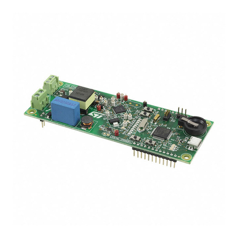
ST eMotion STEVAL-MKI109V1 User manual

March 2011 Doc ID 17768 Rev 1 1/32
UM0979
User manual
STEVAL-MKI109V1 - eMotion
motherboard for MEMS adapter board
Introduction
The STEVAL-MKI109V1 (eMotion) is a motherboard designed to provide the user with a
complete ready-to-use platform for demonstration of MEMS devices mounted on adapter
boards.
The eMotion board uses an STM32F102RB microcontroller which functions as a bridge
between the sensor on the adapter board and the PC, on which it is possible to use the
Unico graphical user interface (GUI) downloadable from the ST website or dedicated
software routines for customized applications.
This user manual describes the hardware included with the demonstration kit and provides
the information required to install and run the demonstration kit user interface.
For details regarding the features of each sensor, please refer to the datasheets available for
each individual device.
www.st.com

Contents UM0979
2/32 Doc ID 17768 Rev 1
Contents
1 Demonstration kit description . . . . . . . . . . . . . . . . . . . . . . . . . . . . . . . . . 5
2 eMotion board installation . . . . . . . . . . . . . . . . . . . . . . . . . . . . . . . . . . . . 9
2.1 Hardware installation . . . . . . . . . . . . . . . . . . . . . . . . . . . . . . . . . . . . . . . . . 9
2.2 DFU . . . . . . . . . . . . . . . . . . . . . . . . . . . . . . . . . . . . . . . . . . . . . . . . . . . . . 11
3 Supported MEMS adapter boards . . . . . . . . . . . . . . . . . . . . . . . . . . . . . 12
4 Supported commands . . . . . . . . . . . . . . . . . . . . . . . . . . . . . . . . . . . . . . 13
4.1 Getting started . . . . . . . . . . . . . . . . . . . . . . . . . . . . . . . . . . . . . . . . . . . . . 13
4.2 Supported commands . . . . . . . . . . . . . . . . . . . . . . . . . . . . . . . . . . . . . . . 13
4.2.1 Commands list and description . . . . . . . . . . . . . . . . . . . . . . . . . . . . . . . 14
4.2.2 Digital output accelerometers: supported commands . . . . . . . . . . . . . . 21
4.2.3 Analog output accelerometers: supported commands . . . . . . . . . . . . . 22
4.2.4 Digital output gyroscopes: supported commands . . . . . . . . . . . . . . . . . 23
4.2.5 Analog output gyroscopes: supported commands . . . . . . . . . . . . . . . . . 24
4.2.6 Digital output pressure sensor: supported commands . . . . . . . . . . . . . 25
4.3 Quick start . . . . . . . . . . . . . . . . . . . . . . . . . . . . . . . . . . . . . . . . . . . . . . . . 25
5 Schematic diagram . . . . . . . . . . . . . . . . . . . . . . . . . . . . . . . . . . . . . . . . . 26
6 Bill of materials . . . . . . . . . . . . . . . . . . . . . . . . . . . . . . . . . . . . . . . . . . . . 28
7 Revision history . . . . . . . . . . . . . . . . . . . . . . . . . . . . . . . . . . . . . . . . . . . 31

UM0979 List of tables
Doc ID 17768 Rev 1 3/32
List of tables
Table 1. Jumper configuration for power-down (PD), self test (ST) and high-pass filter reset (HP). . 8
Table 2. List of supported MEMS adapter boards . . . . . . . . . . . . . . . . . . . . . . . . . . . . . . . . . . . . . . 12
Table 3. Supported commands list . . . . . . . . . . . . . . . . . . . . . . . . . . . . . . . . . . . . . . . . . . . . . . . . . . 14
Table 4. Returned values for *start command . . . . . . . . . . . . . . . . . . . . . . . . . . . . . . . . . . . . . . . . . 16
Table 5. Returned values for *debug command . . . . . . . . . . . . . . . . . . . . . . . . . . . . . . . . . . . . . . . . 17
Table 6. Digital output accelerometers: supported commands list . . . . . . . . . . . . . . . . . . . . . . . . . . 21
Table 7. Analog Output Accelerometers: supported commands list . . . . . . . . . . . . . . . . . . . . . . . . . 22
Table 8. Digital output gyroscopes: supported commands list . . . . . . . . . . . . . . . . . . . . . . . . . . . . . 23
Table 9. Analog output gyroscopes: supported commands list . . . . . . . . . . . . . . . . . . . . . . . . . . . . 24
Table 10. Digital output pressure sensor: supported commands list . . . . . . . . . . . . . . . . . . . . . . . . . 25
Table 11. Bill of materials . . . . . . . . . . . . . . . . . . . . . . . . . . . . . . . . . . . . . . . . . . . . . . . . . . . . . . . . . . 28
Table 12. Document revision history . . . . . . . . . . . . . . . . . . . . . . . . . . . . . . . . . . . . . . . . . . . . . . . . . 31

List of figures UM0979
4/32 Doc ID 17768 Rev 1
List of figures
Figure 1. Demonstration board block diagram . . . . . . . . . . . . . . . . . . . . . . . . . . . . . . . . . . . . . . . . . . . 5
Figure 2. Top silk screen of the eMotion kit . . . . . . . . . . . . . . . . . . . . . . . . . . . . . . . . . . . . . . . . . . . . . 6
Figure 3. Board top view . . . . . . . . . . . . . . . . . . . . . . . . . . . . . . . . . . . . . . . . . . . . . . . . . . . . . . . . . . . 7
Figure 4. Notify icon . . . . . . . . . . . . . . . . . . . . . . . . . . . . . . . . . . . . . . . . . . . . . . . . . . . . . . . . . . . . . . . 9
Figure 5. Hardware update Wizard . . . . . . . . . . . . . . . . . . . . . . . . . . . . . . . . . . . . . . . . . . . . . . . . . . 10
Figure 6. Virtual COM driver port assignment . . . . . . . . . . . . . . . . . . . . . . . . . . . . . . . . . . . . . . . . . . 11
Figure 7. Schematic diagram of the eMotion board (power supply and USB) . . . . . . . . . . . . . . . . . . 26
Figure 8. Schematic diagram of the eMotion board (STM32 and connectors). . . . . . . . . . . . . . . . . . 27

UM0979 Demonstration kit description
Doc ID 17768 Rev 1 5/32
1 Demonstration kit description
The eMotion is a complete demonstration kit that allows demonstration of both digital and
analog MEMS sensors. Thanks to its DIL 24 connector, a wide range of MEMS adapter
boards can be used.
The block diagram of the demonstration kit is shown in Figure 1.
Figure 1. Demonstration board block diagram
As shown in the Figure 1, the eMotion demonstration kit is based on the STM32F102RB
microcontroller and can be connected to the PC through the USB bus. Data coming from the
MEMS sensor connected to the board can be read through the PC GUI provided with the kit.
The eMotion also implements the DFU (device firmware upgrade) feature, therefore, in the
case of a new firmware release, it can be reprogrammed without the need to use a
programmer. See www.st.com/mems for new firmware release.
The eMotion also integrates three general purpose LEDs, two LEDs connected directly to
the interrupt pins of digital adapters and the power/USB LED. Moreover, the eMotion
integrates three buttons: two are available to the user on a dedicated GPIO of the
microcontroller, while the other is used as reset for the microcontroller.
All the MEMS adapter pins are available on two connectors placed on the board (Figure 2
JP2 and JP3).
The top silk screen view and image of the full board are shown in Figure 2 and Figure 3
respectively.
!-V
#ONTROL3WITCHES
RESETLEFTRIGHT
34-&2"
U#
-%-3
DEVICE
53"
#ONNECTOR
30))#
53"
!NALOG
#ONTROLS
340$&3
0OWER/N,%$
)NTERRUPT,%$S
'ENERAL0URPOSE,%$S
7ITH$&5
&EATURE
$),
#ONNECTOR
!NALOG
!$#

Demonstration kit description UM0979
6/32 Doc ID 17768 Rev 1
Figure 2. Top silk screen of the eMotion kit
!-V

UM0979 Demonstration kit description
Doc ID 17768 Rev 1 7/32
Figure 3. Board top view
In order to use the eMotion demonstration kit, installation of a dedicated driver is required,
which is included in the installation pack, together with a GUI interface which allows simple
interaction with the sensor. The steps required for driver and software installation are
described in the following sections.
In Figure 3 some main components placed on the top layer of the eMotion kit are
highlighted.
●Jumpers JP9 and JP10 (Figure 3, ref 10, ref 11) are used to select the STM32 boot
mode. When the eMotion is used together with MEMS adapters, JP9 and J1P0 must be
fitted (see STM32 datasheet for more information).
●Jumper J2 (Figure 3, ref 7) can be used to directly supply the board (from 3.5 V to 6 V)
instead of using the USB connector.
●Jumper JP1 allows the user to measure the sensor current consumption by connecting
a multimeter in series with its terminals (Figure 3, ref 9).
●Jumpers JP4, JP5, and JP6 (Figure 3, ref 8) are used to manually set some features
which are available for just some of the analog MEMS adapters (see Ta b l e 1 for more
details). JP4 is used to set the self test feature, JP5 to handle the power-down pin, and
JP6 to reset the MEMS high-pass filter. When they are fitted on pins 2-3, these
functions are handled by the firmware itself.
!-V
UHI
UHI
UHI UHI
UHI
UHI UHIUHI
UHI
UHI
UHI
UHI
UHI

Demonstration kit description UM0979
8/32 Doc ID 17768 Rev 1
●J1 connector (Figure 3, ref 3) can be used to both reprogram the STM32 and to debug
the code through the JTAG or SWD protocols.
●Jumper JP7 (Figure 3, ref 4) is used to select either JTAG (JP7 unfitted) or SWD (JP7
fitted) mode.
eMotion also integrates six LEDs and three buttons:
●LED D1 (Figure 3, ref 6) is switched on when the board is power supplied.
●LEDs D2 and D3 (Figure 3, ref 13) are directly connected to the interrupt pins of the
MEMS digital adapters (if available on the sensor mounted on the adapter board).
●LEDs D4, D5, and D6 (Figure 3, ref 12) are general purpose LEDs and are used to
indicate some firmware state. For example, LED D6 is switched on when a specific
firmware is selected from those available. LED D5 on indicates that the microcontroller
is well configured for communication with the sensor. Finally the LED D4, blinks
according to the sensor data rate selected.
●Button SW3 (Figure 3, ref 1) is used to reset the STM32.
●Button SW1 and SW2 (Figure 3, ref 2 and ref 5) are connected to STM32 GPIOs and
are available to the user.
Table 1. Jumper configuration for power-down (PD), self test (ST) and high-pass
filter reset (HP)
Jumper on 1-2
position
Jumper on 2-3
position Jumper unfitted
JP4
ST
logic level 1: self test
ON
Self test is handled by
the firmware
logic level 0: self test
OFF, default
JP5
PD
logic level 1: power-
down mode
Power-down is handled
by the firmware
logic level 0: normal
mode, default
JP6
HP
logic level 1: external
high-pass filter reset
High-pass filter reset is
handled by the
firmware
logic level 0: normal
mode, default

UM0979 eMotion board installation
Doc ID 17768 Rev 1 9/32
2 eMotion board installation
The software package can be downloaded from the st.com website and includes the
following directory structure:
●DRIVER: it contains the installation package for the USB drivers needed to connect the
eMotion board to the PC
●DFU: it contains the installation package for the software needed to upgrade the
firmware of the eMotion board (DFU)
●FIRMWARE: it contains the source code of the firmware of the eMotion board together
with the corresponding binary file that can be flashed to the board using the DFU
software.
The sections below describe the procedure to install the driver for the eMotion board and the
DFU software.
2.1 Hardware installation
To install the STM32 virtual COM port driver, launch the “VCPDriver_V1.1_Setup.exe”
included in the package under the “DRIVER” folder and follow the instructions on the
screen. Once the driver is installed, insert the demonstration kit board into a free USB port.
The “Notify” icon should appear, as in Figure 4.
Figure 4. Notify icon
The “Hardware Update Wizard” window then appears (Figure 5), follow the instructions on
the screen to complete the procedure. When driver installations starts, the user is prompted
with the “Hardware Installation” dialog window, click the “Continue Anyway” button.

eMotion board installation UM0979
10/32 Doc ID 17768 Rev 1
Figure 5. Hardware update Wizard
Now the eMotion should be recognized by the PC as a virtual COM. In order to check which
COM port has been assigned to the board, right click on “My Computer” and select
“Manage”, select “Device Manager” and scroll through the list until “Ports(COM & LPT)”. In
the following example (Figure 6) the COM11 has been assigned to the board.

UM0979 eMotion board installation
Doc ID 17768 Rev 1 11/32
Figure 6. Virtual COM driver port assignment
2.2 DFU
To install the DFU software, launch the “DfuSe_Demo_V3.0_Setup.exe” included in the
software package under the “DFU” folder and follow the instructions on the screen. To
launch the software, select “Start > STMicroelectronics > DfuSe > DfuSe Demonstration”.
The MEMS DFU (Device Firmware Update) GUI is a graphical interface that allows the user
to download and replace the firmware of a MEMS product division demonstration board
directly from a PC through the USB port.
The MEMS MKI109V1 demonstration board has the capability of reprogramming an
application through the USB, in accordance with the DFU class specification defined by the
USB Implementers Forum. This capability is useful because it allows to reprogram the
microcontroller directly in the field and is particularly well suited to USB applications where
the same USB connector can be used both for the standard operating mode and for the
reprogramming process.
For more details regarding DFU and the microcontroller ST GUI, see the related user
manual located under “Start > STMicroelectronics > DfuSe > Docs > DfuSe Getting
Started”.

Supported MEMS adapter boards UM0979
12/32 Doc ID 17768 Rev 1
3 Supported MEMS adapter boards
Table 2 below provides the complete list of supported adapter boards.
Table 2. List of supported MEMS adapter boards
Adapter board Device
STEVAL-MKI009V1 LIS3LV02DL
STEVAL-MKI013V1 LIS302DL
STEVAL-MKI015V1 LIS344ALH
STEVAL-MKI082V1 LPY4150AL
STEVAL-MKI083V1 LPY450AL
STEVAL-MKI085V1 LPY410AL
STEVAL-MKI086V1 LPY403AL
STEVAL-MKI087V1 LIS331DL
STEVAL-MKI089V1 LIS331DLH
STEVAL-MKI090V1 LIS331DLF
STEVAL-MKI091V1 LIS331DLM
STEVAL-MKI092V1 LIS331HH
STEVAL-MKI095V1 LPR4150AL
STEVAL-MKI096V1 LPR450AL
STEVAL-MKI097V1 LPR430AL
STEVAL-MKI098V1 LPR410AL
STEVAL-MKI099V1 LPR403AL
STEVAL-MKI105V1 LIS3DH
STEVAL-MKI107V1 L3G4200D
STEVAL-MKI110V1 AIS328DQ
STEVAL-MKI112V1 LPS001WP

UM0979 Supported commands
Doc ID 17768 Rev 1 13/32
4 Supported commands
The microcontroller mounted on the eMotion board is equipped with dedicated firmware that
supports a set of commands which allow to control either the digital or the analog output
MEMS sensor and permits the acquisition of the measured data. The firmware also handles
the communication between the board and the PC through the USB bus. These features
allow the user to easily write their own applications to exploit the capabilities of the sensor
chosen.
This section describes the commands that are supported by the firmware for the
microcontroller of the eMotion demonstration kit.
4.1 Getting started
Before using the commands supported by the firmware, the following procedure must be
performed:
1. Connect the eMotion to the USB port
2. Launch an application which allows to send commands through the virtual serial port.
The remainder of this document assumes the use of “Microsoft© HyperTerminal”
program available with the Windows XP operating system
3. Create a new connection, enter a name (e.g. “STEVAL-MKI0109V1”), and click “OK”
4. In the “Connect Using” field, select the virtual COM port to which the USB port has
been mapped, and click “OK”
5. In port settings, set bits per second to 115200, data bits to 8, parity to none, stop bits to
1, and flow control to none. Click “OK”
6. On the “HyperTerminal” application window choose “files” > “properties” > “settings”,
then click on the “ASCII Setup” button
7. Select “Send line ends with line feeds” and “Echo typed characters locally”
8. Click the “OK” button to close the “ASCII Setup” window
9. Click the “OK” button to close the “Properties” window.
Once this procedure has been completed the user can utilize the commands described in
the following sections by typing them into the “HyperTerminal” window.
4.2 Supported commands
The firmware supports a wide range of MEMS adapters; the next section reports the
complete list of supported commands (see Ta b le 3 ) and their description.
Then, split into sections, the list of commands available for each sensor supported by the
eMotion firmware is reported.

Supported commands UM0979
14/32 Doc ID 17768 Rev 1
4.2.1 Commands list and description
Table 3. Supported commands list
Command Description Returned value
*setdbXXXVY Selects firmware according to the adapter
connected
*start Starts continuous data acquisition (see Ta b l e 4 )
*debug Returns the output data in readable text
format (see Ta b l e 5 )
*stop Stops data acquisition
*Zon Forces 3-state
*Zoff Exits from 3-state
*dev Device name e.g.: LIS3DH
*ver Firmware version e.g.: V1.0
*rAA Accelerometer register read e.g.: RAAhDDh
*wAADD Accelerometer register write
*grAA Gyroscope register read e.g.: GRAAhDDh
*gwAADD Gyroscope register write
*mrAA Magnetometer register read e.g.: MRAAhDDh
*mwAADD Magnetometer register write
*prAA Pressure sensor register read e.g.: PRAAhDDh
*pwAADD Pressure sensor register write
*single It gets a single X, Y, and Z data acquisition (see Ta b l e 5 )
*list Prints the list of MKIs supported e.g.: MKI105V1
*listdev Prints the list of devices supported e.g.: LIS3DH
*echoon Activates the write verbose mode e.g.: RAAhDDh
*echooff Deactivates the write verbose mode
*fifostr Accelerometer “FIFO stream” mode enable st 0 0 0 0 0 0 IR FC FS
*fifomde Accelerometer “FIFO mode” mode enable st 0 0 0 0 0 0 IR FC FS
*fifotrg Accelerometer “stream to FIFO” mode
enable st 0 0 0 0 0 0 IR FC FS
*fiforst Accelerometer “reset” mode enable st 0 0 0 0 0 0 IR FC FS
*gfifostr Gyroscope “FIFO stream” mode enable st 0 0 0 0 0 0 IR FC FS
*gfifomde Gyroscope “FIFO mode” mode enable st 0 0 0 0 0 0 IR FC FS
*gfifotrg Gyroscope “stream to FIFO” mode enable st 0 0 0 0 0 0 IR FC FS
*gfiforst Gyroscope “reset” mode enable st 0 0 0 0 0 0 IR FC FS
*gfifobts Gyroscope “Bypass to FIFO” enable st 0 0 0 0 0 0 IR FC FS
*PDON Set power-down pin

UM0979 Supported commands
Doc ID 17768 Rev 1 15/32
Note: IR: interrupt byte; FC: FIFO control register; FS: FIFO source register.
Set demonstration board
The command *setdbxxxvy selects the part of the firmware able to handle the adapter board
sensor connected to the board. e.g., in order to select the firmware for the LIS3DH the
command must be: setdb105V1. The D6 LED (green) is automatically switched on.
Start command
The *start command initiates the continuous data acquisition. When this command is sent to
the device, it returns a string of bytes (plus carriage return and line feed) similar to “st OUT1
OUT2 OUT3 IR BT”.
The first two bytes are always the ASCII char “s” and “t” which correspond to the
hexadecimal values {73h 74h}.
OUT1, OUT2, and OUT3 are the bytes that contain the values measured at device outputs;
if the output data is represented on more than 8 bits, OUT1, OUT2, and OUT3 are split into
two bytes: high byte (e.g.: “XH”) and low byte (e.g.: “XL”).
IR contains the interrupt bytes and BT contains the bytes that describe the state of the
buttons integrated on the board.
Specifically, bit#0 of the “BT” data corresponds to the status of the SW1 button on the
demonstration kit board: it is set to 1 when the SW1 is pressed (otherwise 0). Bit#1 has the
same behavior but is dedicated to the SW2.
Before sending the *start command, the device must be out from 3-state and some registers
must be configured according to user needs, therefore, *start must be preceded by a *zoff
and some “Register Write” commands.
Table 4 shows the format of the string returned for each device when a *start command is
sent.
*PDOFF Clears power-down pin
*STON Sets self test pin
*STOFF Clears self test pin
*HPON Sets high-pass filter pin
*HPOFF Clears high-pass filter pin
*FSON Sets full scale pin
*FSOFF Clears full scale pin
Table 3. Supported commands list (continued)
Command Description Returned value

Supported commands UM0979
16/32 Doc ID 17768 Rev 1
Note: 1 XH: X axis output high byte (same for Y axis, Z axis, P pressure, and TEMP temperature)
2 XL: X axis output low byte (same for Y axis, Z axis, P pressure, and TEMP temperature)
Debug command
The *debug command starts the continuous data acquisition in debug mode. When this
command is sent to the board, it returns the output values measured by the device
formatted in a readable text format. The values shown on the screen correspond to the LSB
data shown as a decimal number.
Table 5 shows the format of the string returned for each device when a *debug command is
sent.
Table 4. Returned values for *start command
STEVAL # (Device) Returned value
STEVAL-MKI009V1 (LIS3LV02DL)
STEVAL-MKI089V1 (LIS331DLH)
STEVAL-MKI090V1 (LIS331DLF)
STEVAL-MKI091V1 (LIS331DLM)
STEVAL-MKI092V1 (LIS331HH)
STEVAL-MKI105V1 (LIS3DH)
STEVAL-MKI107V1 (L3G4200D)
STEVAL-MKI110V1 (AIS328DQ)
s t XH XL YH YL ZH ZL int1 int2 sw1|sw2 \r \n
STEVAL-MKI013V1 (LIS302DL)
STEVAL-MKI087V1 (LIS331DL) s t X Y Z int1 int2 sw1|sw2 \r \n
STEVAL-MKI015V1 (LIS344ALH) s t XH XL YH YL ZH ZL sw1 sw2 \r \n
STEVAL-MKI082V1 (LPY4150AL)
STEVAL-MKI083V1 (LPY450AL)
STEVAL-MKI085V1 (LPY410AL)
STEVAL-MKI086V1 (LPY403AL)
STEVAL-MKI095V1 (LPR4150AL)
STEVAL-MKI096V1 (LPR450AL)
STEVAL-MKI097V1 (LPR430AL)
STEVAL-MKI098V1 (LPR410AL)
STEVAL-MKI099V1 (LPR403AL)
s t vrefH vrefL o1H o1L out1H out1L out4H out4L o2H o2L
out2H out2L out5H out5L o3H o3L out3H out3L out6H
out6L sw1|sw2 \r \n
STEVAL-MKI112V1 (LPS001WP) s t PH PL TEMPH TEMPL DH DL int1 sw1 sw2 \r \n

UM0979 Supported commands
Doc ID 17768 Rev 1 17/32
Stop command
The *stop command interrupts any acquisition session that has been started with either the
*start or *debug commands.
Zon and Zoff
The *Zon and *Zoff commands are employed, respectively, to put into 3-state the
STM32F102RB microcontroller mounted on the demonstration kit. These commands allow
the isolation of the sensor from the microprocessor and let the user to interact with the
sensor in a pure analog way.
By default, when the kit is first turned on, the lines are in 3-state mode and the user is
required to send the *Zoff command to allow communication between the sensor and the
microcontroller. If Zoff has not been launched, the firmware ignores any other command.
Device name
The *dev command retrieves the name of the adapter connected to the demonstration kit.
The returned value is, for example, “LIS3DH”.
Firmware version
The *ver command queries the demonstration kit and returns the version of the firmware
loaded in the microprocessor, for example, “V1.0”.
Table 5. Returned values for *debug command
STEVAL # (Device) Returned value
STEVAL-MKI009V1 (LIS3LV02DL)
STEVAL-MKI013V1 (LIS302DL)
STEVAL-MKI015V1 (LIS344ALH)
STEVAL-MKI087V1 (LIS331DL)
STEVAL-MKI089V1 (LIS331DLH)
STEVAL-MKI090V1 (LIS331DLF)
STEVAL-MKI091V1 (LIS331DLM)
STEVAL-MKI092V1 (LIS331HH)
STEVAL-MKI105V1 (LIS3DH)
STEVAL-MKI110V1 (AIS328DQ)
X=XXXXX Y=YYYYY Z=ZZZZZ
STEVAL-MKI082V1 (LPY4150AL)
STEVAL-MKI083V1 (LPY450AL)
STEVAL-MKI085V1 (LPY410AL)
STEVAL-MKI086V1 (LPY403AL)
STEVAL-MKI095V1 (LPR4150AL)
STEVAL-MKI096V1 (LPR450AL)
STEVAL-MKI097V1 (LPR430AL)
STEVAL-MKI098V1 (LPR410AL)
STEVAL-MKI099V1 (LPR403AL)
VREF=VVVVV OUT1=XXXXX 4OUT1=XXXXX
OUT3=YYYYY OUT6=YYYYY
STEVAL-MKI107V1 (L3G4200D) P=PPPPP R=RRRRR Y=YYYYY
STEVAL-MKI112V1 (LPS001WP) P=PPPPP T=TTTTT D=DDDDD

Supported commands UM0979
18/32 Doc ID 17768 Rev 1
Accelerometer register read
The *rAA command allows the contents of the accelerometer registers in the demonstration
kit board to be read. AA, expressed as a hexadecimal value and written in upper case,
represents the address of the register to be read.
Once the read command is issued, the board returns RAAhDDh, where AA is the address
sent by the user and DD is the data present in the register.
For example, to read the register at address 0x20, the user issues the command *r20, which
returns, e.g., R20hC7h.
Accelerometer register write
The *wAADD command allows writing to the contents of the accelerometer registers in the
demonstration kit board. AA and DD, expressed as hexadecimal values and written in upper
case, represent, respectively, the address of the register and the data to be written. For
example, to write 0xC7 to the register at address 0x20, the user issues the command
*w20C7.
Gyroscope register read
The *grAA command allows the contents of the gyroscope registers in the demonstration kit
board to be read. AA, expressed as hexadecimal value and written in upper case,
represents the address of the register to be read.
Once the read command is issued, the board returns GRAAhDDh, where AA is the address
sent by the user and DD is the data present in the register.
For example, to read the register at address 0x20, the user issues the command *gr20,
which returns, e.g., GR20hC7h.
Gyroscope register write
The *gwAADD command allows writing to the contents of the gyroscope registers in the
demonstration kit board. AA and DD, expressed as hexadecimal values and written in upper
case, represent, respectively, the address of the register and the data to be written. To write
0xC7 to the register at address 0x20, for example, the user issues the command *gw20C7.
Magnetometer register read
The *mrAA command allows the contents of the magnetometer registers in the
demonstration kit board to be read. AA, expressed as a hexadecimal value and written in
upper case, represents the address of the register to be read.
Once the read command is issued, the board returns MRAAhDDh, where AA is the address
sent by the user and DD is the data present in the register.
For example, to read the register at address 0x00, the user issues the command *mr00,
which returns, e.g., MR00h10h.
Magnetometer register write
The *mwAADD command allows writing to the contents of the magnetometer registers in
the demonstration kit board. AA and DD, expressed as hexadecimal values and written in
upper case, represent, respectively, the address of the register and the data to be written. To
write 0x20 to the register at address 0x01, for example, the user issues the command
*mw0120.

UM0979 Supported commands
Doc ID 17768 Rev 1 19/32
Pressure sensor Register read
The *prAA command allows the contents of the pressure sensor registers in the
demonstration kit board to be read. AA, expressed as a hexadecimal value and written in
upper case, represents the address of the register to be read.
Once the read command is issued, the board returns PRAAhDDh, where AA is the address
sent by the user and DD is the data present in the register.
For example, to read the register at address 0x20, the user issues the command *pr20,
which returns, e.g., PR20h10h.
Pressure sensor Register write
The *pwAADD command allows writing to the contents of the pressure sensor registers in
the demonstration kit board. AA and DD, expressed as hexadecimal values and written in
upper case, represent, respectively, the address of the register and the data to be written. To
write 0xC7 to the register at address 0x20, for example, the user issues the command
*pw20C7.
Single acquisition
The *single command may be used to read just one set of data. It requires the sensor to be
well configured and once invoked, returns the read values of one data sample.
The format of the returned value is exactly the same as the *debug command (Ta b l e 5 ), in
fact, the *debug command is used for continuous data acquisition purposes whereas a
*single command returns just one set of data.
List
The *list command returns the list of MKI adapters supported by the firmware, printed in
ASCII format.
Listdev
The *listdev command returns the list of devices supported by the firmware, printed in ASCII
format.
Echo on
The *echoon command is used to activate the write command verbose mode. Once this
command is launched, after every write command the firmware automatically performs also
a read of the register just written. This function is useful to check if the write has succeeded.
For instance, if the *echoon command is launched, after a *w2027 it results R2027.
Echo off
The *echooff command stops the write command verbose mode.
Accelerometer FIFO stream mode enable
The *fifostr command is used to enable the accelerometer FIFO stream mode. For more
details see the AN3308 application note.

Supported commands UM0979
20/32 Doc ID 17768 Rev 1
Accelerometer FIFO mode enable
The *fifomde command is used to enable the accelerometer FIFO mode. For more details
see the AN3308 application note.
Accelerometer Stream to FIFO mode enable
The *fifotrg command enables the accelerometer stream to FIFO mode. For more details
see the AN3308 application note.
Accelerometer FIFO reset enable
The *fiforst command enables the accelerometer FIFO reset mode. For more details see the
AN3308 application note.
Gyroscope FIFO stream mode enable
The *fifostr command is used to enable the gyroscope FIFO stream mode.
Gyroscope FIFO mode enable
The *gfifomde command is used to enable the gyroscope FIFO mode.
Gyroscope Stream to FIFO mode enable
The *gfifotrg command enables the gyroscope stream to FIFO mode.
Gyroscope FIFO reset enable
The *gfiforst command enables the gyroscope FIFO reset mode.
Gyroscope FIFO bypass to stream enable
The *gfifobts command enables the gyroscope bypass to stream mode.
PDON and PDOFF
The *PDON and *PDOFF commands are employed respectively to set to 1, and to clear to
0, the “power-down” pin in analog devices.
STON and STOFF
The *STON and *STOFF commands are employed respectively to set to 1, and to clear to 0,
the “self test” pin in analog devices.
HPON and HPOFF
The *HPON and *HPOFF commands are employed respectively to set to 1, and to clear to
0, the “high-pass filter” pin in analog devices.
FSON and FSOFF
The *FSON and *FSOFF commands are employed respectively to set to 1 and to clear to 0
the “full scale” pin in analog devices.
Other manuals for eMotion STEVAL-MKI109V1
2
Table of contents
Other ST Motherboard manuals

ST
ST STEVAL-BTDP2 User manual

ST
ST STEVAL-IHM022V1 User manual

ST
ST STEVAL-ILL009V1 Installation and operating instructions

ST
ST STEVAL-IFS001V1 User manual

ST
ST L9679E-EVB User manual

ST
ST STEVAL-DIGAFEV1 User manual

ST
ST STEVAL-SP1ML915 User manual

ST
ST STEVAL-IDB011V1 User manual

ST
ST PractiSPIN UM0696 User manual

ST
ST STM32G474E-EVAL User manual

ST
ST STEVAL-MKI005V1 User manual

ST
ST SPC582B-DIS User manual

ST
ST B-L4S5I-IOT01A User manual

ST
ST NUCLEO-F411RE Manual

ST
ST STM32100B-EVAL User manual

ST
ST FDA803S User manual

ST
ST EVAL-TDA7803A User manual

ST
ST STEVAL-STRKT01 Administrator Guide

ST
ST STEVAL-IPP003V1 Quick start guide

ST
ST STEVAL-USBPD45H Administrator Guide