FIC 1stMainboard VG33 User manual

VG33
MAINBOARD
MANUAL
DOCNo.: M02A04
Rev. |:A0
Date |:1, 2003
Part No. |: 25-10630-00

Handling Precautions
Warning:
1. Static electricity may cause damage to the integrated circuits on
the motherboard. Before handling any motherboard outside of its
protective packaging, ensure that there is no static electric charge
in your body.
2. There is a danger of explosion if the battery is incorrectly
replaced. Replace only with the same or an equivalent type
recommended by the manufacturer.
3. Discard used batteries according to the manufacturer’s
instructions.
4. Never run the processor without the heatsink properly and firmly
attached. PERMANENTDAMAGE WILLRESULT!
Observe the following basic precautions when handling the motherboard
or other computer components:
Wear a static wrist strap which fits around your wrist and is
connected to a natural earth ground.
Touch a grounded or anti-static surface or a metal fixture such as a
water pipe.
Avoid contacting the components on add-on cards, motherboards,
and modules with the golden fingers connectors plugged into the
expansion slot. It is best to handle system components by their
mounting brackets.
The above methods prevent static build-up and cause it to be discharged
properly.
Trademark
All trademarks mentioned in this manual are registered properly of
the respective owners.
Handling Precautions
Thismanual maynot, inwhole orin part,be photocopied,reproduced,
transcribed, translated, or transmitted in whatever form without the
written consent of the manufacturer, except for copies retained by the
purchaser for personal archival purposes.
Notice

i
Table of Contents
Table of Contents
Chapter 1 Overview
Package Checklist .......................................................................... 1-2
TheVG33Mainboard ................................................................ 1-3
Main Features................................................................................ 1-4
Chapter 2 Installation Procedures
QuickReference (fromPage2-2 to 2-4) .......................................... 2-2
Mainboard Layout .................................................................... 2-2
(1).ClearCMOS ................................................................ 2-3
(2). Front Panel Block Cable Connection ........................... 2-3
(3).CPU Fan Installation.................................................... 2-4
1).SetSystem Jumper .................................................................... 2-4
ClearCMOS:JP3 ............................................................... 2-4
2). Install Memory Modules .......................................................... 2-5
3). Install the CPU .......................................................................... 2-5
4). Install Expansion Cards ............................................................. 2-7
5). ConnectDevices ....................................................................... 2-8
FloppyDisketteDrive Connector ...................................... 2-8
IDEDevice Connectors ..................................................... 2-9
Power Connectors ............................................................. 2-9
CDAudio-In Connectors................................................... 2-10
FrontPanel Block,Power LED, IR,andSpeaker Connector
.......................................................................................... 2-10
Fan Connectors ................................................................. 2-12
Wake-On-Lan Connector................................................... 2-12
Wake-On-Ring Connector ................................................. 2-13
SPDIF Out Connector ....................................................... 2-13
SerialIRQ Connector......................................................... 2-14
Quick Reference (German) G-1
Quick Reference (French) F-1
Quick Reference (Spanish) S-1
Quick Reference (Japanese) J-1
Quick Reference (Chinese) C-1
Quick Reference (Simplified Chinese) |||||||||||||SC-1

ii
VG33MainboardManual
PS/2 Keyboard and Mouse Connector.............................. 2-14
Universal Serial Bus Connectors....................................... 2-14
Serial Port Connectors....................................................... 2-15
Printer Connector .............................................................. 2-16
Audio I/O Jacks ................................................................ 2-16
VideoGraphicsAccelerator Connector .............................. 2-17
LAN Connector ................................................................. 2-17
IEEE1394 Connectors (mfg.optional) ............................... 2-18
Chapter 3 BIOS Setup
Main Features Setup...................................................................... 3-1
Advanced Features Setup ............................................................. 3-3
Onboard device Configuration.................................................. 3-5
I/O device Configuration ........................................................... 3-6
Hardware Monitor ..................................................................... 3-7
Power Features Setup .................................................................... 3-8
Boot Features Setup ...................................................................... 3-9
Exit Features Setup ........................................................................ 3-10

1 - 1
Overview
Overview
Chapter 1
The new microATX 1stMainboard®VG33 supports a full range of the latest
generation Intel®Pentium®4 CPUs. The leading edge chipset Intel®845GE
MCH was designed for coworking with Pentium®4 in the mPGA478 CPU
socket based on VRM 9.X spec. and 533 MHz FSB. Being built by the leading
edge technology, the Intel Pentium®4 processors provide a significant perfor-
mance over previous Pentium®III processors. Onboard two DDR SDRAM
sockets supportDDR333 SDRAM for up to 2GB memory capacity.The ICH4
brings the ATA100 IDE performance and its high-speed interface further en-
sures that data transfer speeds are improved, especially for six USB 2.0 periph-
eral devices. The board also features onboard audio with either 2-channel or
5.1-channel.
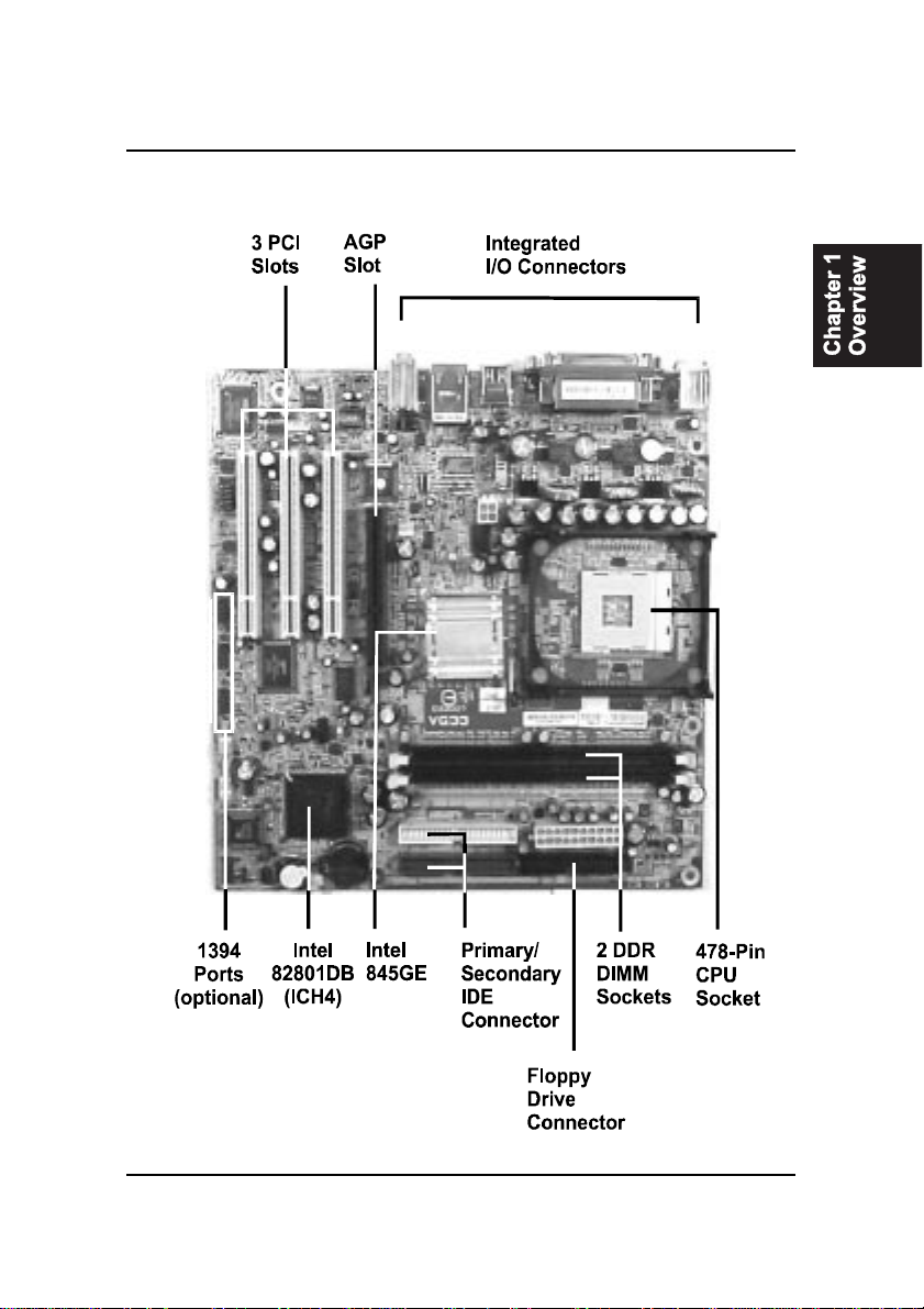
The board comes with a versatile range of I/O features such as 2 serial ports,
three optional 1394 ports (pinheaders onboard), 1 parallel port, 1 LAN, 1 IR, 1
PS/2 mouse and keyboard connector, 6 USB 2.0 ports (two of them are in one
pinheader), 1 media connector (front audio pinheader, Line-in, Line-out and
Mic-in).Ample expansion is available through 3 PCI, 1AGP slot to meet the
requirementfor fully makinguseof theP4CPU benefits ininternetapplicatons,
video/3D graphics performance, and so forth.
Other key features are Remote On/Off, Auto Power Failure Recovery, inte-
grated temperature monitoring and system fan control. Included also is a CD,
1st Utilities, with enhanced drivers.

1 - 2
VG33MainboardManual
NOTE: lst Utilities CD that contains patch files, onboard video/au-
dio chip drivers, related online help and other useful information
can be found in your mainboard package.
Please install it right after your Windows operating system installa-
tion is done.Place your lst Utilities CD in the drive, an operating
menu will appears in your monitor. Please select Auto Installation.
It will automatically detect which software tools (patch files, drivers)
that the mainboard needs. Press OK button to go through the whole
installation procedure in a very straight forward and easy way. It
also provides you with a custom way to select wanted patch files
and software drivers that for onboard chips use. The top menu of
thelst Utilities CDlistsallthefunctions that allowedbythisboard.
NOTE: Aboutthe USB2.0 driver.
if you use-
Windows XP + Sevice Pack 1: it offers the driver.
Windows XP: download it from Microsoft web site.
Windows 2000/98SE/ME:
driver in lst Utilities CD, please manually installed it.
Package Checklist
If you discover any item below was damaged or lost, please contact your
vendor.
;The mainboard ;This user manual
;OneFDDcable ;|SoftwareCD
;OneATA/100 cable ;|I/O shilding
1 - 3
Overview
The VG33 Mainboard

1 - 4
VG33MainboardManual
Main Features
Easy Installation
||BIOS with support for Plug and Play, auto detection of IDE hard drives,
||LS-120|drives, IDE ZIPdrives,Windows 98SE,Windows ME, Windows
||NT,Windows 2000, Windows XP, and OS/2.
Leading Edge Chipset
Intel®845GE supports integrated graphic (UMA only) features that of 32
bpp true color and flat panel monitors. The ICH4 provides SMBus 2.0
support,20-bitAC97 audio, 6USB2.0ports,andUltraATA100 IDEperfor-
mance between mainboard and peripheral devices.
Versatile Main Memory Support
Acceptsupto 2GBDDRSDRAMusing two memory socketsforallowing
thatfrom64, 128,256,512MB,1GBwith support forlightenning-fastDDR
SDRAM(DDR200/266/333MHz).
Super Multi Input/Output (I/O) Support
Integrated Plug and Play multi-I/O chipset features two high-speed UART
16550 compatible serial ports, one parallel port and one FDDconnector.
AGPand PCI Expansion Slots
One AGP Bus that supportsAGP (only 1.5VAGP 4X card allowed) and
three PCI Bus expansion slots provided the room to install a full range of
add-on cards.
Intel P4 Processors Support
1.4Gto2.5GHzandup*(FSB400) /Celeron1.7-2.0GHzandup*(FSB400)
2.0Gto3.06GHz andup* (FSB 533)
(*: not tested yet)

1 - 5
Overview
Integrated Audio Subsystem
Enhanced PCI BusMaster IDEController with UltraDMA33/66/100
Support
Integrated Enhanced PCI Bus Master IDE controller features two dual-
channel connectors that up to four Enhanced IDE devices, including CD-
ROM and Tape Backup Drives, as well as Hard Disk Drives supporting
thenew UltraATA100protocol. Standard PIOMode 3,PIOMode 4,DMA
Mode 2, DMA Mode 4, UltraDMA-100 Mode 5 devices are also sup-
ported.
Convenient Rear Panel USB Connection Support
Four USB ports integrated in the rear I/O panel and one USB pinheader for
two USB ports to allow the connecting with either front or rear panel jacks
in a convenient way and high-speed Plug and Play connection to the USB
2.0 compliant peripheral devices on the market.
Onboard audio features included one SPDIF pinheader for digital audio
resource output use. The onboard AC97 Codec chip has two options:
either supports 2-channel or optional 5.1-channel audio feature. If the
latter one onbaord, the Microphone/Line_In/Line_Out can be used as
audio output.
LAN Support
Onboard optional LAN controller with one optional RJ45 jack integrated
with other rear panel I/O connectors pvovides users with a convenient
connection with network environment.
1394 Support (optional)
One optional 1394 controller with three optional 2x5 pinheaders of 1394
ports (Intel spec.) for more efficient peripheral device connection and
data transaction.

1 - 6
VG33MainboardManual
The Page Left Blank for Note

2 - 1
Installation Procedures
Chapter 2
Installation Procedures
The mainboard has several user-adjustable jumpers on the board that allow you to
configure your system to suit your requirements. This chapter contains information
on the various jumper settings on your mainboard.
To set up your computer, you must complete the following steps:
Step 1 - Set system jumpers
Step 2 - Install memory modules
Step 3 - Install the Central Processing Unit (CPU)
Step 4 - Install expansion cards
Step 5 - Connect ribbon cables, cabinet wires, and power supply
Step 6 - Set up BIOS software
Step 7 - Install supporting software tools
WARNING: Excessive torque may damage the mainboard. When
using an electric screwdriver on the mainboard, make sure that
the torque is set to the allowable range of 5.0 ~ 8.0kg/cm.
Mainboard components contain very delicate Integrated Circuit
(IC) chips. To prevent static electricity from harming any of the
sensitive components, you should follow the following precau-
tions whenever working on the computer:
1. Unplug the computer when working on the inside.
2. Hold components by the edges and try not to touch the IC
||||chips, leads, or circuitry.
3. Wear an anti-static wrist strap which fits around the wrist.
4. Place components on a grounded anti-static pad or on the bag
that came with the component whenever the components are
separated from the system.

2 - 2
VG33MainboardManual
Quick Reference (from Page 2-2 to 2-4)
Mainboard Layout
*When linktoLine_Outjack,pleaseuse aspeakerthatwith amplifier.
*Connector SerialIRQ isfor systemintegrationuse.
2 - 3
Installation Procedures
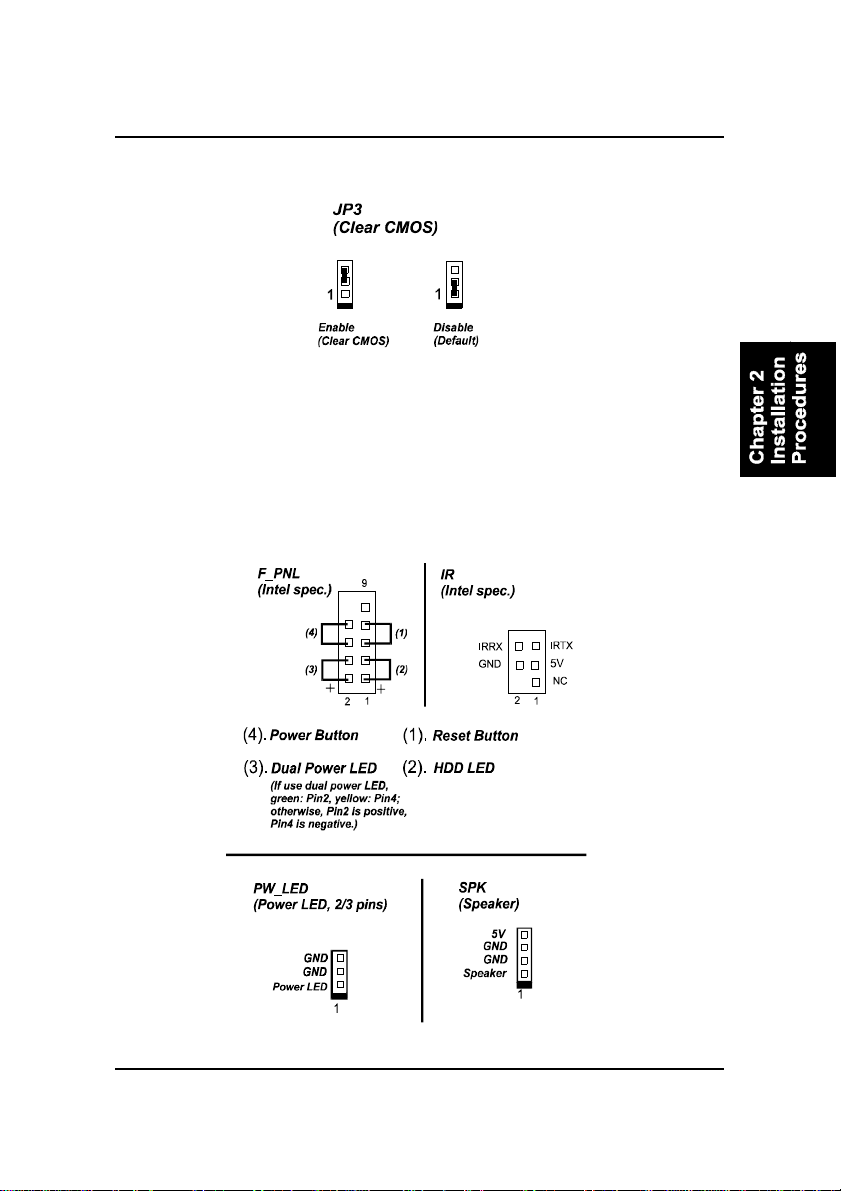
(1). ClearCMOS
(2). FrontPanel Block CableConnection

2 - 4
VG33MainboardManual
1). Set System Jumper
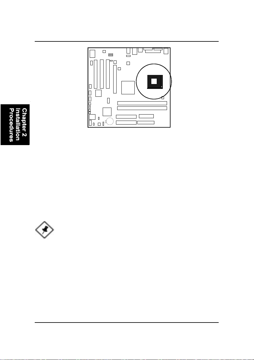
(3). CPUFanInstallation
This connector is linked to the CPU fan. When the system is in some power saving
mode, the CPU fan will turn off; when it reverts back to full on mode, the fan will turn
back on. Without sufficient air circulation, the CPU may overheat resulting in
damage to both the CPU and the mainboard.
Damage may occur to the mainboard and/or the CPU fan if these pins are
usedincorrectly. Theseare notjumpers, donotplace jumpercaps overthese
pins.
Clear CMOS: JP3
The CMOS RAM is powered by the onboard button cell battery. To clear the
RTC data: (1) Turn off your computer (2) Place the jumper cap onto the pinpair
2-3 at least 6 seconds to enable CMOS clearance (3) Place the jumper cap onto
the pinpair 1-2 to disable the effect of CMOS clearance (4) Turn on your com-
puter until CMOS checksum error appears (5) Hold down the Deletekey when
boots (6) Enter the BIOS Setup to re-enter user preferences.

2 - 5
Installation Procedures
Press the clips with both hands to remove the DIMM.
2). Install Memory Modules
1. Locate the DIMM slots on the mainboard.
2. Install the DIMM straight down into the DIMM slot using both hands.
3. The clip on both ends of the DIMM slot will close up to hold the DIMM
in place when the DIMM reaches the slot bottom.
3). Install the CPU
The mainboardhasbuilt-in SwitchingVoltage Regulator tosupport CPUVcore
autodetection. That is, it has the ability to detect and recognize the CPU volt-
age, clock and ratio.
2 - 6
VG33MainboardManual
To install the CPU, do the following:
1. Lift the lever on the side of the CPU socket.
2. Handle the chip by its edges and try not to touch any of the pins.
3. Place the CPU in the socket. Do not force the chip. The CPU should slide
easily into the socket.
4. Swing the lever to the down position to lock the CPU in place.
5. Place the cooling fan with heatsink on top of the installed CPU.
When you install your CPU on this mainboard, please use a power supply that
designed and manufactured only for CPU use. Your CPU fansink combined
with its retention module must be completely closed and firmly attached on the
top of the processor.
NOTE: Users The CPU installing procedures should be:
1. Insert the CPU (with its fansink and retention module) on the
socket.
2. Connect the 4-pin plug of the power supply.
3. Connect the 20-pin plug of the power supply
To remove the processor, please do it in reverse order.

2 - 7
Installation Procedures
4). Install Expansion Cards
This section describes how to connect an expansion card to one of your
system expansion slots. Expansion cards are printed circuit boards that, when
connected to the mainboard, increase the capabilities of your system. For
example, expansion cards can provide video and sound capabilities. The
mainboard features oneAGP and three PCI bus expansion slots.
CAUTION: Make sure to unplug the power supply when adding or
removing expansion cards or other system components. Failure to
do so may cause severe damage to both the mainboard and
expansioncards.
Always observe static electricity precautions.
Please read Handling Precautions at the start of this manual.
To install an expansion card, follow the steps below:
1. Remove the computer chassis cover and select an empty expansion
slot.
2. Remove the corresponding slot cover from the computer chassis.
Unscrew the mounting screw that secures the slot cover and pull
the slot cover out from the computer chassis. Keep the slot cover
mounting screw nearby.
2 - 8
VG33MainboardManual
5. Secure the board with the mounting screw removed in Step 2. Make
sure that the card has been placed evenly and completely into the
expansion slot.
6. Replace the computer system cover.
7. Setup the BIOS if necessary.
8. Install the necessary software drivers for the expansion card.
3. Holding the edge of the peripheral card, carefully align the edge
connector with the expansion slot.
4. Push the card firmly into the slot. Push down on one end of the
expansion card, then the other. Use this rocking” motion until the add
on card is firmly seated inside the expansion slot.
5). Connect Devices
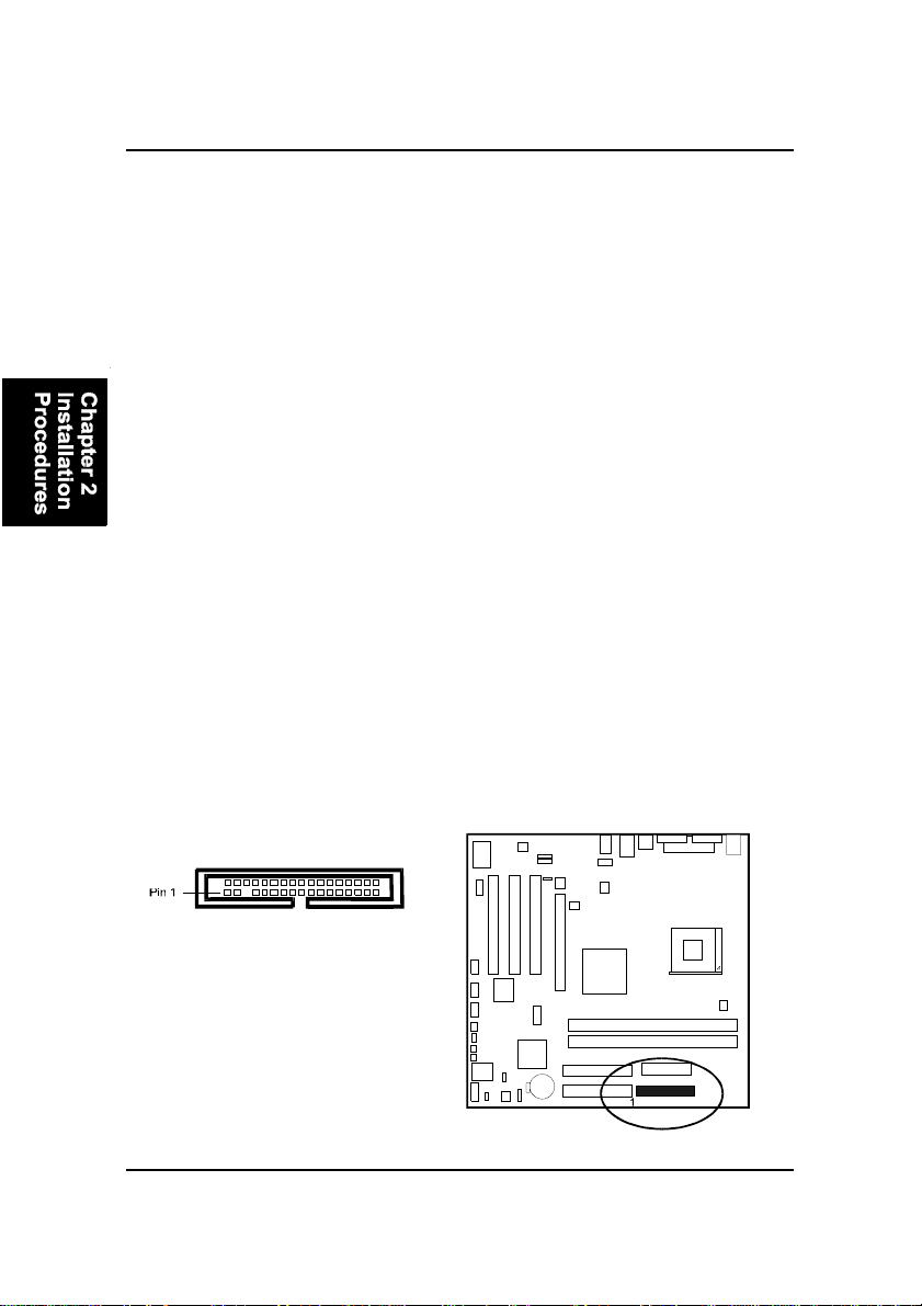
Floppy Diskette Drive Connector
This connector provides the connection with your floppy disk drive.
The red stripe of the ribbon cable must be the same side with the Pin 1.

2 - 9
Installation Procedures
Power Connectors
The 20-pin male block connector is connected to theATX power supply. The
4-pinmale blockconnector isfor the 12Vpower use. Theconnectors are linked
with yourATX power supply. The plug from the power supply will only insert
in one orientation because of the different hole sizes. Find the proper orienta-
tion and push down firmly making sure that the pins are aligned.
IDE Device Connectors
These two connectors are used for your IDE hard disk drives, CD drives, LS-
120|drives, or IDE ZIP drives. The red stripe of the ribbon cable must be the
same side with the Pin 1.
2 - 10
VG33MainboardManual
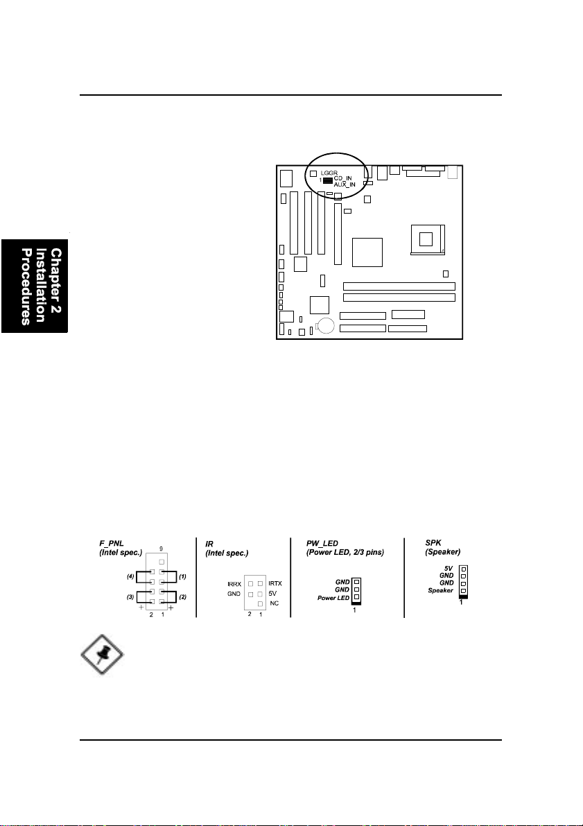
Front Panel Block, Power LED, IR, and Speaker Connector
This block connector includes the connectors for linking with Power LED (3-
pin), HDD LED, power button, power/sleep/message waiting button, reset
buttonon the front panel of the system case. Please identify polarities of plug
wires for the case speaker and LEDs. Please ask vendor about this information
when you buy themand install the system by yourself. The plug wires polari-
ties of these buttons will not affect the function.
CD Audio-In Connectors
The connectors, CD_IN and AUX_IN, are for CD-ROM drive audio analog
input use.
NOTE: Users that want to use IR port must set BIOS feature UART
Mode Select to set COM2 at IrDA or ASKIR mode depending re-
quest.
Table of contents
Other FIC Motherboard manuals


