Trac About IRV2000 User manual

TRAC ABOUT, INC.
IRV2000
OWNERS MANUAL
Trac About, Inc.
Newton, Kansas
316-283-5660

An open letter to the owner of
THE TRAC ABOUT
MODEL IRV2000
PLEASE READ THE OPERATORS PART OF THIS MANUAL
BEFORE OPERATING THE IRV2000
Thank you for choosing the Trac About IRV2000. We sincerely hope it
will allow you much more freedom to go where you would like to go. The
IRV2000 was made for safety and ease of going where you would like to go. It
operates quite well inside a home, school, shopping mall, church or any building
that will accept motorized chairs. It’s construction and low center of gravity make
the machine extremely safe.
Outdoors the IRV2000 is unsurpassed for its ability to take you over rough
terrain, through mud, snow, and seaside sand. It can cross curbs and other
obstructions up to 4-5 inches if you cross them at a slight angle. THE IRV2000
WILL NOT GO UP A STAIRWAY.
To get the most enjoyment and use of your IRV2000, you really should
read the manual before operating. We have tried to make it brief and to the point.
We hope you enjoy.
If for any reason you have a problem with the IRV2000, please call Trac
About Inc. at 1-800-458-8616 or e-mail from the web site, www.tracabout.com.
Sincerely at your service,
The gang at Trac About Inc.

TRAC ABOUT, INC.
1801 SE 9th ST., PO BOX 502, NEWTON, KS.67114-0502
316-283-5660*800-458-8616*FAX316-283-0693
www.tracabout.com
A PERSONAL AGREEMENT
BETWEEN THE OWNER AND TRAC ABOUT INC.
I do hereby agree that this IRV2000 (serial number_________________) has been
demonstrated to the best of my understanding. I will ask an authorized
representative of TRAC ABOUT INC. if I should have any questions in the future
about operation or maintenance. I will first go the Web page of
www.tracabout.com to find my answer by directly reading or by E-mail. I will call
1-800-458-8616 if I don’t have access to the INTERNET or if I need more help.
I understand this IRV2000 has been setup for me and only me. Any other person
that operates it will do so at their own risk. TRAC ABOUT INC. nor any person
associated will not be held accountable for any damage or injury done by the
operation of this machine.
Signed _______________________________ Date________________
(check one or both)
Owner
Operator
I agree to allow TRAC ABOUT, INC. to use my name, comments and or photos
for promotional uses in demonstrating the abilities of the IRV 2000. I understand
that there will be no monetary gain now or in the future from TRAC ABOUT’S
use of my name, comments and or photos.
I give permission __________ I do not give my permission _________
(Initial) (Initial)
w
ord/tracbout/manual\ownagre.doc

Table of Contents Table of Contents
Trac About IRV2000 Trac About IRV2000
BY TOPIC BY PAGE NUMBER
Battery charge Indicator lights................ Page 3,5 Safety Tips............................................. Page 1
Battery charging...................................... Page 6 Introduction to the IRV2000....................Page 1
Battery replacement................................ Page 6 Speed selection....................................... Page 2,4
Bearing replacement............................... Page 12 Unlocking the Joystick (80 amp Controller). Page 2
Changing the Batteries.............................Page 6 Locking the Joystick (80 amp Controller).Page2
Charging the battery.................................Page 6 Joystick panel explanation.......................Page 2,4
Cleaning and Washing.............................Page 13 INSTRUCTIONS OF OPERATION.......Page 2,4
Drive pin replacement..............................Page 9 Battery charge Indicator lights..................Page 3,5
Lights flashing...................................... Page 10 Track and Wheel positions........................Page 3,5,8
INSTRUCTIONS OF OPERATION.......Page 2,4 Battery charging......................................Page 6
Introduction to the IRV2000....................Page 1 Charging the battery.................................Page 6
Jack operation......................................... Page 7, 7a Changing the Batteries.............................Page 6
Joystick panel explanation.......................Page 2,4 Battery replacement.................................Page 6
Lights flashing, what do they mean...........Page 10 Jack operation......................................... Page 7, 7a
Locking the Joystick (80 amp Controller). Page 2 Track adjustment.......................................Page 7, 7a
Safety Tips............................................. Page 1 Unlocking the drive pins..........................Page 9
Speed selection....................................... Page 2,4 Stalling or Power out problem..................Page 11
Stalling or Power out problem..................Page 11 Lights flashing.................................. Page 10
Track adjustment.......................................Page 7, 7a Trouble shooting section.........................Page 10,11
Track and Wheel positions........................Page 3,5,8 Lights flashing, what do they mean...........Page 10
Track replacement.....................................Page 7, 7a Track replacement.....................................Page 7, 7a
Trouble shooting section…......................Page10,11 Bearing replacement…..............................Page 12
Unlocking the drive pins….......................Page 9 Drive pin replacement…...........................Page 9
Unlocking the Joystick (80 amp Controller) Page 2 Cleaning and Washing…..........................Page 13
Warranty…............................Appendices
Radio and Interference….......Appendices
Parts list and parts location ..Appendices
Circuit Breaker (if equipped)…. Appendices Battery Replacement for Elevating Seating System
(if equipped)................................................................. Appendices
Inserted pages for Penny Giles 120 Amp
Controller (No page numbers)

OWNERS MANUAL
THE TRAC ABOUT
MODEL IRV2000
YOU MUST READ THIS MANUAL BEFORE FIRST OPERATING THE IRV2000.
Thank you for purchasing the TRAC ABOUT IRV2000.Please read at least the
first 3 pages before operating the machine.
We would like to hear from you with any comments or suggestions about the IRV2000.
Please call 1-800-458-8616. Any changes or new information can be found on our web
site at www.tracabout.com.
OPERATION SAFETY
The IRV2000 has been built and tested to allow you more freedom and safety then most
other vehicles on the market. The safety suggestions listed below, are to help you enjoy
as much pleasure as possible.
Always wear your seat belt. The IRV2000 is designed for your safety and
pleasure out of doors. Sometimes the going could get a little rough.
If the battery lights show two red and one amber, you need to return and charge the
batteries. Do not charge the batteries if the battery charger is wet.
Do not drive the IRV2000 in vehicle areas. It is not a legal street vehicle.
It is not recommended to drive parallel on an incline greater than 15 degrees.
Do not drive up a slop of more than 20 degrees. BACK THE MACHINE UP A
STEEP GRADE, going forward may cause it to go over backwards.
Do not ride the IRV2000 on a ramp that is not rated for at least 1000 pounds.
Do not unlatch the drive pins and let it coast down hill. You will not have control.
Do not drive in water deeper than the top of the track.
If you drive the IRV2000 on an ocean beach, wash off all salt each day.
Do not high pressure wash under the seat mount. (This is where all the electronics
for the IRV2000 resides. After washing let the machine set until all water is gone.
Do not operate the IRV2000 if the controls are wet.)
Lock the Joystick controller when leaving the IRV2000 unattended.
WARNING: Allow only one person at a time on the IRV2000. Violation of the machine
could result in personal injury or property damage.
Page 1
12-05-00

INSTRUCTIONS TO OPERATE THE IRV2000
The Instructions of Operation are intended for you to have the most fun and the least
amount of frustrations while you operate the IRV2000. Please read the first 3 pages AND
page 11 of this manual before attempting to operate your new machine.
Keep in mind that the IRV2000 weights about 400 pounds without an operator. It can
cause damage to persons and property if not operated properly.
You can mount the IRV2000 from either side of the seat simply by raising the arm of the
seat. Sit down, spin in the seat and lower the arm rest. FASTEN YOUR SEAT BELT.
YOU ARE READY TO GO WHERE YOU WOULD LIKE TO GO!! The following
topics will explain the operation of each element of the Joystick controller.
GETTING STARTED USING THE 80 AMP
CONTROLLER
(If you have the100 amp controller, please see pages 4,5)
The following is an explanation of the Joystick
control.
Press the long I|O button. If the Joystick will not
work, you will see a little red light flashing on the
Key Location. Touch the magnetic key on the Key
Location red light.This will allow the Joystick to
activate. (If you want to re-lock the Joystick, have
power on and touch the magnetic key on the Key
Location red light.)
You will also see the Battery Lights come on. If
the battery is fully charged, you will see two red
lights, two yellow lights and two green lights. You
will see in the Speed Indicator window the speed number or actuator letter. “A” or “b”
SELECTING SPEEDS
Press the Speed Selector until you see a “1” appear in the Speed
Indicator window. If you press the Speed Selector again, you will
see a “2” appear in the window.
The Joystick has a total of five speeds. The higher the number the faster the IRV 2000
will go. To change to a lower speed you must continue to press the button through the
speeds and letters to obtain the desired speed. You will see a letter appear after speed “5”.
Refer to the section WHEEL POSITIONS for an explanation. ( NOTE: beginning
operation in speed is advisable “1” or “2” until you are familiar with the operation of the
Joystick.)
Speeds are the result of power levels. If you need more power you need to select a higher
speed setting and then adjust the ground speed by moving the lever slightly.
Page 2 03-29-02
Selector
Speed
Battery Charger
Plug-in
Battery Lights
System
Status
LED
Speed Indicator
Key Location
Joy Stick
Speed
Selector
1/0
Off-On
Horn
Power Plug-in

DRIVING THE IRV 2000 WITH THE JOYSTICK
Moving the Joystick forward will drive the IRV 2000 forward. If you push the stick just a
little, you will go slow. If you push it a lot, you will go as fast as the Speed Indicator is
set. If you move the stick a little to the left or right, you will turn in that direction in a
large circle. If you move it a lot, you will turn very short. If you pull back on the stick,
you will go backwards. If you release the Joystick you will stop abruptly. Try to move
the Joystick very smoothly to avoid sudden jerks.
WHEEL POSITIONS
SEE PAGE 8 FOR DIAGRAM
If you continue to press the Speed Selector again and again, you will see an “A” or a “b”
in the Speed Indicator window. These letters are used to raise and lower the tail wheel
“A” or the large center wheels “b”. Move the lever sideways to change the letter. Now if
you push forward or pull back on the Joystick, the wheel will go down or up. Try to
cross obstacles at an angle. You can cross a 5" curb safely if you cross at an angle.
Cross small logs and ditches the same way.
NOTE: If you run the center wheels all the way down and the caster all the way down,
you now have a three-point setup that allows tight turns on hard surfaces as well as on
carpet and throw rugs.
BATTERY LIGHTS
The Joystick controller has six battery lights. They will show how much charge is left in
the batteries. When the batteries are fully charged, all six lights will light. As the batteries
loose their charge, the green light will be the first to quit. If both of the green and yellow
lights go out, you have approximately 15 minutes before the machine quits. You can run
the batteries down to the point that the left (red) light will begin to
flash. When that happens, you do not have much time left. The
battery charge life will depend on the load and the terrain. You
should never leave the battery with a low charge. It will damage the
batteries over time.
Battery Lights
If the IRV2000 has a problem, normally the little red light on the I\O begins to flash.
Turn to the section titled, TROUBLE SHOOTING and follow the instructions.
NOTE: IF THE IRV2000 IS LEFT OUTDOORS OR IF YOU WANT HIGH
SECURITY, UNPLUG THE JOYSTICK AND REMOVE IT FROM THE ARMREST.
Page 3 03-29-02

GETTING STARTED USING THE 100 AMP CONTROLLER
(If you have the 80 amp controller, please see pages 2,3)
The following is an explanation of the Joystick
control. Press the round OFF/ON Button. If
the Joystick will not work, you will see the
Battery Lights flashing. Refer to the flash code
section.
Battery Charger
Plug-in Location Off/On
Otherwise, you should see the Battery Lights
and the Speed Indicator Lights come on
without flashing. If the battery is fully charged,
you will see three red lights, four yellow lights
and three green lights. Also notice the Speed
Indicator Lights (1-5), indicating what speed
range the unit is in, one light being the slowest
speed available.
SELECTING SPEEDS
Press the Speed/Mode Selector button. You should see the
Speed Indicator Lights flash. Move the Joystick Lever to the
right to increase speed, and to the left to decrease speed. To
operate in that speed, simply move the Lever forward or back. You can also
change speed while moving by pressing the Speed/Mode Selector button. The
Joystick has a total of five speeds.
( NOTE: beginning operation in speed “1” or “2” lights is advisable until you are
familiar with the operation of the Joystick.)
DRIVING THE IRV 2000 WITH THE JOYSTICK
Moving the Joystick forward will drive the IRV 2000 forward. If you push the
stick just a little, you will go slow. If you push it a lot, you will go as fast as the
Speed Indicator is set. If you move the stick a little to the left or right, you will
turn in that direction in a large circle. If you move it a lot, you will turn very short.
If you pull back on the stick, you will go backwards. If you release the Joystick
you will stop abruptly.
Try to move the Joystick very smoothly to avoid sudden jerks.
Page 4 03-29-02
Battery
Lights
JoyStick
Lever
Wheel Location
Lights
Speed/Mode
Selector
MODE
Speed Indicator
Lights
Horn
Button

WHEEL POSITIONS
SEE PAGE 8 FOR DIAGRAM
If you press the Speed/Mode Selector twice, you will see one of the
two red Wheel Location Lights come on in the wheelchair picture. This
mode is used to raise and lower either the tail wheel or the large center
wheels, depending on which red light is lit. The light in the “seat
bottom” is for the center wheels. The light in the “seat back” is for the tail wheel.
Move the lever sideways to change the location. Now if you push forward or pull
back on the Joystick, the wheels will go down or up. Try to cross obstacles at an
angle. You can cross a 5" curb safely if you cross at an angle. Cross small logs
and ditches the same way.
NOTE: If you run the center wheels all the way down and the tail wheel all the way
down, you now have a three-point setup that allows tight turns on hard surfaces as
well as on carpet and throw rugs.
BATTERY LIGHTS
The Joystick controller has ten Battery Lights. They will show how much charge
is left in the batteries. When the batteries are fully charged, all ten lights will light.
As the batteries loose their charge, the green lights will be the first to quit. If all of
the green and yellow lights go out, you have approximately 15
minutes before the machine quits. You can run the batteries down
to the point that the last red light will begin to flash. When that
happens, you do not have much time left. The battery charge life
will depend on the load and the terrain. You should never leave the
battery with a low charge. It will damage the batteries over time.
If the IRV2000 has a problem, normally the Battery Lights begin to flash. Turn to
the section titled, TROUBLE SHOOTING and follow the instructions.
NOTE: IF THE IRV2000 IS LEFT OUTDOORS OR IF YOU WANT HIGH
SECURITY, UNPLUG THE JOYSTICK AND REMOVE IT FROM THE
ARMREST.
Page 5 03-29-02

PG DRIVES TECHNOLOGY R-NET TECHNICAL MANUAL- OPERATION
1 Introduction
The relevant contents of this chapter should be included in the wheelchair’s operating guide. Further copies are available from
PGDT in either written or disk (Adobe PDF) format. Copies should not be made without the express permission of PG Drives
Technology.
The operation of the R-net varies dependent on programming. This chapter covers all types of operation. It is the responsibility of
the wheelchair manufacturer to ensure that only the relevant sections of this chapter are included in the wheelchair’s operating
manual.
The operation of the R-net wheelchair control system is simple and easy to understand. The control system incorporates state-of-
the-art electronics, the result of many years of research, to provide you with ease of use and a very high level of safety. In
common with other electronic equipment, correct handling and operation of the unit will ensure maximum reliability.
Please read this chapter carefully - it will help you to keep your wheelchair reliable and safe.
2 General
An R-net control system comprises a minimum of two modules - Joystick Module and Power Module. Because of the modular
design, the depth of the control system can be greatly increased. The following diagram shows the basic set-up.
2.1 Handling
Avoid knocking your control system and especially the joystick. Be careful not to strike obstacles with the control system or joystick
when you drive. Never drop the control system.
When transporting your wheelchair, make sure that the control system is well protected. Avoid damage to cables.
2.2 Operating Conditions
Your control system uses industrial-grade components throughout, ensuring reliable operation in a wide range of conditions.
However, you will improve the reliability of the control system if you keep exposure to extreme conditions to a minimum.
SK77981/4 13

R-NET TECHNICAL MANUAL- OPERATION PGDRIVES TECHNOLOGY
Do not expose your control system or its components to damp for prolonged periods. If the control system becomes
contaminated with food or drink clean it off as soon as possible.
2.3 Cleaning
Clean the control system and the joystick with a cloth dampened with diluted detergent. Be careful when cleaning the joystick
and screen.
Never use abrasive or spirit-based cleaners.
3 Mating Connectors
To connect the Communication Cables:
• Holding the connector housing, firmly push the connector into its mate until you can no longer see the yellow
plastic.
The connectors are secured using a friction system.
To disconnect the Communication Cables:
• Holding the connector housing firmly, pull the connectors apart.
Do not hold or pull on the cable. Always grip the connector when connecting and disconnecting.
When the control system is first switched on after a connection, or system component change the
Timer will be displayed whilst the system checks itself and then the Re-start icon will be
displayed. Switch the control system off and on again to operate.
SK77981/414

PG DRIVES TECHNOLOGY R-NET TECHNICAL MANUAL- OPERATION
4 Controls
The R-net control system has two versions of Joystick Module – with and without lighting control. Most of the controls are common
to both however, the lighting buttons are only included on Joystick Module with lighting control. Each of the controls is explained
within this section.
SK77981/4 15

R-NET TECHNICAL MANUAL- OPERATION PGDRIVES TECHNOLOGY
4.1 Joystick
The primary function of the joystick is to control the speed and direction of the wheelchair. The further you push the joystick from
the center position the faster the wheelchair will move. When you release the joystick the brakes are automatically applied.
If the wheelchair is fitted with actuators, the joystick can also be used to move and select actuators, refer to section 3.8 for more
details.
4.2 Buttons
4.2.1 On/off Button
The on/off button applies power to the control system electronics, which in turn supply power to the wheelchair’s motors. Do not
use the on/off button to stop the wheelchair unless there is an emergency. (If you do, you may shorten the life of the wheelchair
drive components).
4.2.1 Horn Button
The Horn will sound while this button is depressed.
4.2.2 Speed Decrease Button
This button decreases the maximum speed setting.
Depending on the way the control system has been programmed a momentary screen may be displayed when the button is
pressed.
Refer to section 5 for details of the momentary screen
Refer to Chapter 3 - Programming for details.
SK77981/416

PG DRIVES TECHNOLOGY R-NET TECHNICAL MANUAL- OPERATION
4.2.3 Speed Increase Button
This button increases the maximum speed setting.
Depending on the way the control system has been programmed a momentary screen may be displayed when the button is
pressed.
Refer to section 5 for details of the momentary screen
Refer to Chapter 3 - Programming for details.
4.2.4 Mode Button
The Mode button allows the user to navigate through the available operating Modes for the control system. The available modes
are dependant on programming and the range of auxiliary output devices connected to the control system.
Refer to Chapter 3 - Programming for details.
4.2.5 Profile Button
The Profile button allows the user to navigate through the available Profiles for the control system. The number of available Profiles
is dependant on how the control system is programmed.
Depending on the way the control system has been programmed a momentary screen may be displayed when the button is
pressed.
Refer to section 5 for details of the momentary screen
Refer to Chapter 3 - Programming for details.
4.2.6 Hazard Warning Button and LED
This button activates and de-activates the wheelchairs hazard lights. Depress the button to turn the hazards on and depress the
button again to turn them off.
When activated the hazard LED and the indicator LED’s will flash in sync with the wheelchair’s indicators.
4.2.7 Lights Button and LED
This button activates and de-activates the wheelchairs lights. Depress the button to turn the lights on and depress the button
again to turn them off.
When activated the lights LED will illuminate.
4.2.8 Left Indicator Button and LED
This button activates and de-activates the wheelchair’s left indicator. Depress the button to turn the indicator on and depress the
button again to turn it off.
When activated the left indicator LED will flash in sync with the wheelchair’s indicator.
4.2.9 Right Indicator Button and LED
This button activates and de-activates the wheelchair’s right indicator. Depress the button to turn the indicator on and depress
the button again to turn it off.
When activated the right indicator LED will flash in sync with the wheelchair’s indicator.
4.2.10 External On/off Switch Jack
This allows the user to turn the control system on and off using an external device, such as a buddy button.
SK77981/4 17

R-NET TECHNICAL MANUAL- OPERATION PGDRIVES TECHNOLOGY
4.2.11 External Profile Switch Jack
This allows the user to select Profiles using an external device, such as a buddy button.
To change the Profile whilst driving simply press the button.
If the control system is set to latched drive or actuator control operation, then the polarity of the jack input is reversed to effect a
fail safe system; meaning this input will provide an External Profile Switch function and an Emergency Stop Switch function.
The Joystick Module is supplied with rubber bungs that must be inserted into the Jack Socket
when no external device is connected.
4.3 LCD Screen
The status of the control system can be understood by observing the LCD screen. The control system is on when the screen is
backlit.
Refer to section 5 for details on screen symbols.
4.5 Charger Socket
This socket should only be used for charging or locking the wheelchair. Do not connect any type of programming cable into this
socket.
Refer to section 10 for more details on charging.
This socket should not be used as a power supply for any other electrical device. Connection of other electrical devices may
damage the control system or affect the E.M.C. performance of the wheelchair.
The control system’s warranty will be voided if any device other than a battery charger supplied,
with the wheelchair, or the lock key is connected into this socket.
5 LCD Screen - Monochrome
The status of the control system can be understood by observing the LCD screen.
5.1 Screen Symbols
The Drive screen for the R-net has common components, which will always appear, and components that will only appear under
certain conditions. Below is a view of a typical Drive screen in Profile 1.
SK77981/418

PG DRIVES TECHNOLOGY R-NET TECHNICAL MANUAL- OPERATION
5.1.1 Battery Indicator
This displays the charge available in the battery and can be used to alert the user to the status of the battery.
Steady
This indicates that all is well.
Flashing Slowly
The control system is functioning correctly, but you should charge the battery as soon as possible.
Stepping Up
The wheelchair batteries are being charged. You will not be able to drive the wheelchair until the
charger is disconnected and you have switched the control system off and on again.
Refer to section 11 for a description of how to read the Battery Gauge.
5.1.2 Speed Indicator
This displays the current speed setting.
The speed setting is adjusted using the Speed Buttons.
5.1.3 Current Profile
The Profile Number describes which Profile the control system is currently operating in.
The Profile Text is the name or description of the Profile the control system is currently operating in.
5.1.4 In Focus
When the control system contains more than one method of direct control, such as a secondary
Joystick Module or a Dual Attendant Module, then the Module that has control of the wheelchair
will display the In Focus symbol.
5.1.5 Speed Limit
If the speed of the wheelchair is being limited, for example by a raised seat, then this symbol will
be displayed.
If the wheelchair is being inhibited from driving, then the symbol will flash.
5.1.6 Latched
When the control system is operating in a latched condition this symbol will be displayed.
SK77981/4 19

R-NET TECHNICAL MANUAL- OPERATION PGDRIVES TECHNOLOGY
5.1.7 Restart
When the control system requires a reboot; for example, after a module re-configuration, this
symbol will be flashed.
5.1.8 Fault
The control system can detect a wide variety of errors. When the system has detected an error
that is not severe enough to cause the system to trip, then this symbol will be displayed.
5.1.9 Motor Temperature
This symbol is displayed when the control system has intentionally reduced the power to the
motors, in order to protect them against heat damage.
5.1.10 Control System Temperature
This symbol is displayed when the control system has intentionally reduced its own power, in order
to protect itself against heat damage.
5.1.11 Timer
This symbol is displayed when the control system is changing between different states. An
example would be entering into Programming Mode. The symbol is animated to show the sands
falling.
5.1.12 E-Stop
If the control system is programmed for latched drive or actuator operation, then it is normal for
an Emergency Stop Switch to be connected into the External Profile Switch Jack.
If the Emergency Stop Switch is operated or disconnected, this symbol will flash.
5.1.13 Environmental
When Environmental Mode is entered the screen will display the following icon.
5.1.14 Bluetooth
SK77981/420
When Bluetooth Mode is entered the screen will display the following icon.

PG DRIVES TECHNOLOGY R-NET TECHNICAL MANUAL- OPERATION
5.2 Momentary Screens
If the momentary screens are programmed to be displayed then pressing the Speed or Profile Buttons will display screens such as
below.
Speed Momentary Screen Profile Momentary Screen
5.3 Diagnostic Screen
When the control system safety circuits have operated and the control system has been prevented from moving the wheelchair
a diagnostics screen will be displayed.
This indicates a system trip, i.e. the R-net has detected a problem somewhere in the wheelchair’s electrical system.
If the error is in a non-active module, for example in the ISM but with a drive Profile is selected, then drive will still be possible,
however, the diagnostic screen will appear intermittently.
5.3.1 Identified Module
This identifies which module of the control system has registered the problem.
PM Power Module
JSM Joystick Module
ISM Intelligent Seating/lighting Module
5.3.2 Trip Text
The Trip Text gives a brief description of the trip type.
5.3.3 Trip Code
The 4 digit code displayed gives the exact trip that has been recorded.
5.3.4 Diagnostic Procedure
Please follow this procedure:
• Read and note the Trip Text displayed, the identified Module and the Trip Code.
• Switch off the control system.
SK77981/4 21

R-NET TECHNICAL MANUAL- OPERATION PGDRIVES TECHNOLOGY
• Make sure that all connectors on the listed Module and the wheelchair are mated securely.
• Check the condition of the battery.
• Find the definition of the Trip Code in the Service Guide, and take the required action.
• Switch on the control system again and try to drive the wheelchair. If the safety circuits operate again, switch off
and do not try to use the wheelchair. Contact your service agent.
Example:
Identified Module Power Module Trip.
Trip Text Low Battery
Trip Code 2C00
This means the battery needs charging or there is a bad connection to the battery.
• Check the connections to the battery. If the connections are good, try charging the battery.
5.4 Locking the Control System
The Control System can be locked in one of two ways. Either using a button sequence on the keypad or with a physical Key. How
the Control System is locked depends on how the wheelchair manufacturer has programmed the system.
5.4.1 Keypad Locking
To lock the wheelchair using the keypad;
• While the control system is switched on, depress and hold the On/off button.
• After 1 second the control system will beep. Now release the On/off button
• Deflect the joystick forwards until the control system beeps.
• Deflect the joystick in reverse until the control system beeps.
• Release the joystick, there will be a long beep.
• The wheelchair is now locked.
The following screen will be displayed.
If an LED Joystick Module is fitted the Speed Indicator LED’s will ripple from left to right. Refer to Chapter 4.
SK77981/422

PG DRIVES TECHNOLOGY R-NET TECHNICAL MANUAL- OPERATION
To unlock the wheelchair;
• If the control system has switched off, press the On/off button.
• Deflect the joystick forwards until the control system beeps.
• Deflect the joystick in reverse until the control system beeps.
• Release the joystick, there will be a long beep.
• The wheelchair is now unlocked.
5.4.2 Key Locking
To lock the wheelchair with a key;
• Insert and remove a PGDT supplied key into the Charger Socket on the Joystick Module.
• The wheelchair is now locked.
The following screen will be displayed.
To unlock the wheelchair;
• If the control system has switched off, press the On/off button.
• Insert and remove a PGDT supplied key into the Charger Socket.
• The wheelchair is now unlocked.
•
5.5 Actuator Selection Screen
To adjust the seat position the actuator screen must be visible.
Depress the Mode Button to scroll through the Mode screens until you reach the actuator screen, displayed below.
Actuator adjustment is achieved as follows.
• Move the Joystick sideways to select the desired axis.
(This is indicated by the section of the wheelchair that is highlighted)
• Move the joystick forwards and backwards to move the actuator.
SK77981/4 23
Table of contents
Popular Wheelchair manuals by other brands

Vermeiren
Vermeiren Inovys II-E instruction manual

Care & Independence
Care & Independence COMFORT VALUE CVSC/ATT user guide

Ortopedia
Ortopedia ALLROUND 970 operating manual

Invacare
Invacare 9000 Topaz Owner's operator and maintenance manual

Pride Mobility
Pride Mobility LUXOR owner's manual
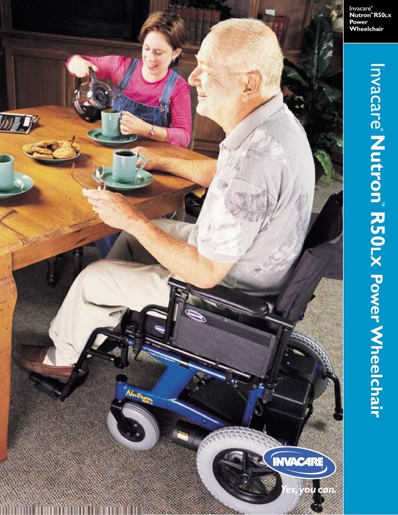
Invacare
Invacare Nutron R50LX Specifications


