Care & Independence COMFORT VALUE CVSC/ATT User manual

ISSUE DATE: 17/03/22
VERSION: UG/CVSC-EN02
STATUS: APPROVED
AUTHORISED BY: Technical Director
……………………………..
J. ASH
CVSC/ATT: COMFORT VALUETM Shower Chair
- Attendant
CVSC/ATT: COMFORT VALUETM Shower Chair
- Self Propel
THIS USER GUIDE IS APPLICABLE
FOR THE FOLLOWING
COMFORT VALUETM
SHOWER CHAIRS:
Chair Model:
Serial Number:
User Name:
The chair model and serial number
are located on the label on the chair frame.
CE EU93/42
Care & Independence Ltd is a UK manufacturer registered with
MHRA as a Class 1 Medical Device Manufacturer and meets the
essential requirements set out in Annex 1 of the Medical
Device Directive 93/42EEC.
VALUE
Comfort
TM
Declaration
Care & Independence Ltd, declares under its sole responsibility
that the aforementioned products to which this declaration
relates, and which bear the CE marking, are in conformity with
the applicable requirements of EC Directive 93/42/EEC
(Amended by 2007/47/EC) as transposed in the laws of the
Member States.
The COMFORT VALUETM Shower Chair is designed to
be used as a attendant-operated or self-propel
model. All the parts being interchangeable to
facilitate simple change of operation should this
be required.
The standard CVSC/ATT and the standard
CVSC/SP chair is only supplied in one
configuration, with the option of additional parts
being purchased separately. Please contact Care
& Independence concerning additional parts.

1. GENERAL
WARRANTY:
The COMFORT VALUETM bathing products covered in
this User Guide have been awarded a ONE YEAR
WARRANTY on the stainless steel frame and a
TWO YEAR WARRANTY on all other components.
Any manufacturing defect will be rectified free of
charge. Product damage through wear and tear,
neglect or accidental damage is not covered by
the warranty.
2 yr
2. BATHING CHAIR SAFETY
2.1 GENERAL:
2.1.1. Only competent persons should ever use
bathing equipment.
2.1.2 A risk assessment must be completed
before using the chair.
2.1.3 It is essential that the equipment is fit for
purpose; the correct size and type of chair
for an individual is essential to ensure the
safety and comfort of the user.
2.1.4 Product care and inspection instructions
should be followed at all times.
2.1.5. No bathing equipment must ever be used
to lift more than its rated load (see label).
2.1.6 We advise that vulnerable users are not left
unattended when using this equipment.
2.1.6 If there is any doubt about equipment
safety, remove the equipment from use
until checked and authorised for use by a
competent person.
2.2 BATHING EQUIPMENT INSPECTION:
Care & Independence recommend pre-use
equipment checks by a competent person to
ensure the equipment is free from defects.
4. PRODUCT CARE
4.1 GENERAL CARE:
4.1.1 Gas struts should be inspected and
lubricated where necessary - if in doubt,
please contact your supplier.
4.1.2. Discolouration to some materials or fading
labels may occur as a result of use over
time.
NOTE: It is a recommended that the
product label remain legible throughout
the product’s working lifetime but is not
currently a statutory requirement.
3. DAMAGED OR FAULTY BATHING PRODUCT
Care & Independence have a strict Returns &
Repair Procedure to ensure the safety of all
involved.
Please do not send bathing products back
without completing the Return/Repair form.
4.2 CLEANING THE EQUIPMENT:
·Clean seat, vinyl parts and frame with a damp
cloth together with a mild soap solution or
cleaning agent.
Do not use bleach or agents containing
bleach.
·Towel dry after use. Any materials should be
disposable and dealt with in an
environmentally-friendly manner.
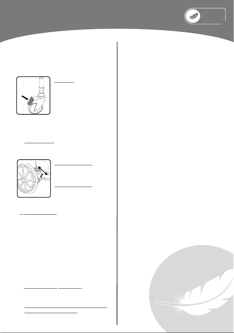
·Keep castors / wheels free from limescale,
soap, hairs and fibres.
4.3 DECONTAMINATION:
Please be aware of any infection control
policies that may in force locally or
appropriate to multi-user scenarios.
FURTHER INFORMATION:
Available to download from our website
i
UG/CVSC-EN02
·Returns & Repair Procedure

2
5. GETTING TO KNOW YOUR CHAIR
5.1 THE SHOWER CHAIR STYLE
5.2 PRODUCT LABELS EXPLAINED
There is one label associated with each product. Made from coated polyester for durability in wet
environments, it is located on the cross frame beneath the seat.
UG/CVSC-EN02
VALUE
Comfort
TM
Braked casters (4)
Chair handles (2)
Frame
Fold-up foot rest (2)
Moveable arm rest (2)
Backrest
Gap seat
Commode pan
ATTENDANT STYLE
SELF PROPEL STYLE
Braked casters (2)
Chair handles (2)
Handbrake
Backrest
Self Propel wheel (2)
Site of Commode pan
Frame
Moveable arm rest (2)
Gap seat
Fold-up foot rest (2)
MPC
SERIAL NUMBER
CONTACT DETAILS
PRODUCT CODE
MAXIMUM USER WEIGHT
DATE

6. OPERATIONAL INSTRUCTIONS
Please read this User Guide carefully before using the CVTIS chair.
Any person who is likely to use the equipment needs to familiarise themselves with the user instructions.
6.1 SEATING
6.1.1 Removal and Fitting.
The chair is fitted with a gap front / horseshoe seat
as standard, secured with grey snap-on clips.
To remove the seat: pull
seat upwards sharply.
To fit the seat: align the
snap-on clips and push
and/or press down firmly.
6.1.2 Adjusting the Seat Height (Attendant model only)
i. Remove the pin clip from the leg.
ii. Select the desired seat height by sliding out the
leg from the frame (This is a telescopic action).
iii. Refit pin clip.
iv. Repeat the adjustment for the other legs.
v. Ensure all legs are adjusted equally.
NOTE:Height adjustment can only be achieved when
the chair is not in use.
6.2 BACKREST
The backrest is not fixed to the main frame of the
chair.
To remove / fit the backrest:
Simply slide the backrest over the chair framework
6.3 ARMRESTS
The armrest is a self-supporting arm. The armrests
must not be used to help manoeuvre the chair, push
handles are supplied for this reason.
To raise the arm:
lift / fold upwards.
To lower the arm:
pull / fold downwards.
6.4 FOOTREST
Do not stand on the footrests as this may result in the
chair tipping. The footrests have been designed to be
removed or folded away to ease access to and from
the chair.
6.4.1 Removal
The footrest is designed to swing away. It is
detachable by a simple single-handed operation.
To lock: The footrest is locked in place by a V-groove
and a plastic clip.
To remove the footrest: lift upwards.
6.4.2 Adjustment
The footrests are adjustable in height:
i. Remove the footrest from the frame by pulling
upwards.
ii. Remove the black pin on the side footrest
socket.
iii. Refit pin in required hole.
iv. Refit footrest.

6.5.2 Self-Propel Model
A) Brake Operation
Self-propelling models are fitted with a hand
brake.
To operate the brake: push
forward on the brake lever
until it locks in place
To release the brake: pull back
on the brake lever.
6.5 BRAKED WHEELS & CASTORS
6.5.1 Attendant Model
Attendant chairs are fitted with brake castors
(identified by a red pedal). This is a foot-operated
brake.
Operation:
i. Press down with the toe of
the foot onto the front of the
pedal to operate the brake.
Ii. Push back on the pedal to
release.
UG/CVSC-EN02
VALUE
Comfort
TM
ii. Remove the locking nut & washer from
the axle bolt.
iii. Select the position for the wheel and
insert the axel bolt through the
mounting plate.
iv. Re-fit the washer and locking nut
(locking nut should be replaced by a new
nut)
v. Repeat the processes for the opposite
wheel, ensuring that the axle bolt is
positioned in the same hole on the
mounting plate.
Adjustment of the front castors to match the rear
wheels is also required. See 6.1.2 for instruction.
Where any accessories have been ordered, they will
be dispatched with the chair and when appropriate,
already fitted into place for your convenience.
A separate User Guide will accompany accessories.
B) Brake Adjustment
Required: suitably sized allen key wrench [not supplied]
i. Release the allen key bolt on the brake-
mounting block.
ii. With the brake in the fully released position
slide the brake to the required position
(leaving a gap of approx. 15mm between the
brake and the tyre).
iii. Re-tighten the allen key bolt.
Repeat operation for the opposite side.
C) Wheel Adjustment (Metal Plate)
(Required: a 19mm spanner, socket and ratchet are
required [not supplied]).
To change / adjust the size, height or position
of the self-propelling wheels:
i. Remove the covers from the axle bolts
and wheel centre.
7. ACCESSORIES

Free product training is also offered.
Please contact us for further
information.
www.careandindependence.com
Care & Independence Ltd,
Unit 3, Telford Business Centre,
Telford Road, Bicester, OX26 4LD
033 012 80808
Monday - Friday 08.30 -17.00
©2022 Care & Independence Ltd All Rights Reserved.
Contents of this publication are intended as a guide only. Although
due care and attention has been given to ensure that instructions
are accurate and correct, in case of doubt, please refer to your
prescribing clinician or contact the Care & Independence team on
033 012 80808. Care & Independence Ltd reserve the right to
modify, add or delete details and is under no obligation to notify
the user of amendment. All data is correct at time of printing.
SCAN QR CODE FOR;
·Product information
·User Guide
·Expert advice
·Full support
·Faded label replacement
·Chair repair
If a third party supplier has provided the equipment,
you may like to write their contact details here:
Table of contents
Other Care & Independence Wheelchair manuals

Care & Independence
Care & Independence Warwick Cradle User manual

Care & Independence
Care & Independence Adult TIS Shower Chair User manual

Care & Independence
Care & Independence Grasshopper User manual

Care & Independence
Care & Independence COMFORT VALUE Series User manual

Care & Independence
Care & Independence Bariatric 981 User manual

Care & Independence
Care & Independence COMFORT VALUE CVSC/ATT User manual