Ortopedia ALLROUND 970 User manual

1
OperatingManual
S T A Y M O B I L E
ElectricWheelchair
ALLROUND 970

32
4.9 Ramps and lifting platforms.............................................................................................24
4.9.1 Special safety information:................................................................................... 25
5. Components................................................................................................................. 26
5.1 Seat .................................................................................................................................. 26
5.1.1 Seat cushion ......................................................................................................... 26
5.1.2 Adjusting the seat depth ..................................................................................... 26
5.1.3 Swivelling up the seat ......................................................................................... 27
5.1.4 Swivelling down the seat..................................................................................... 28
5.2 Backrest ............................................................................................................................ 29
5.2.1 Attaching/detaching the ERGOpor backrest element ......................................... 29
5.2.1.1 Detaching the ERGOpor backrest element......................................... 29
5.2.1.2 Attaching the ERGOpor backrest element .........................................29
5.2.1.3 ERGOpor backrest cushion .................................................................. 29
5.2.2 Standard backrest................................................................................................ 30
5.2.2.1 Folding down the backrest ................................................................. 30
5.2.2.2 Folding upright the backrest .............................................................. 30
5.2.3 30° backrest ......................................................................................................... 31
5.2.3.1 Adjusting the backrest angle.............................................................. 31
5.2.3.2 Detaching the 30° backrest ................................................................ 32
5.2.3.3 Attaching the 30° backrest ................................................................. 32
5.2.4 Electrically height-adjustable backrest ................................................................ 32
5.2.4.1 Detaching the backrest element ........................................................ 32
5.2.4.2 Attaching the backrest element ......................................................... 33
5.2.4.3 Folding down the electric backrest .................................................... 33
5.2.4.4 Folding up the electric backrest ......................................................... 33
5.3 Armrests ........................................................................................................................... 34
5.3.1 Adjusting to suit the seat depth .......................................................................... 34
5.3.2 Height adjustment............................................................................................... 35
5.3.3 Detaching the armrest......................................................................................... 35
5.4 Clothing protector ........................................................................................................... 36
5.5 Legrests ............................................................................................................................ 36
5.5.1 Calf strap ............................................................................................................. 37
5.5.2 Detaching the legrests......................................................................................... 37
5.5.6 Hanging in the legrests ....................................................................................... 37
5.5.7 Adjusting the height of the foot plate ................................................................. 37
5.5.8 Height-adjustable legrests .................................................................................. 38
5.5.8.1 Detaching the legrests ....................................................................... 38
5.5.8.2 Hanging in the legrests ...................................................................... 38
5.5.8.3 Adjusting the height of the foot plate ................................................ 38
5.5.8.4 Adjusting the height of the legrests ................................................... 39
5.5.8.5 Positioning the calf pad...................................................................... 39
5.5.9 Electrically height-adjustable legrests ................................................................. 40
5.5.9.1 Detaching the legrests ....................................................................... 40
5.5.9.2 Hanging in the legrests ...................................................................... 40
5.5.9.3 Adjusting the height of the foot plate ................................................ 40
5.5.9.4 Positioning the calf plate .................................................................... 40
Table of contents
1. Foreword........................................................................................................................ 6
2. Legal requirements ....................................................................................................... 7
2.1 Legal requirements for Germany ....................................................................................... 7
2.1.1 Electric wheelchairs with a top speed of 6 km/h ................................................... 7
2.1.2 Electric wheelchairs with a top speed of 10 km/h ................................................. 7
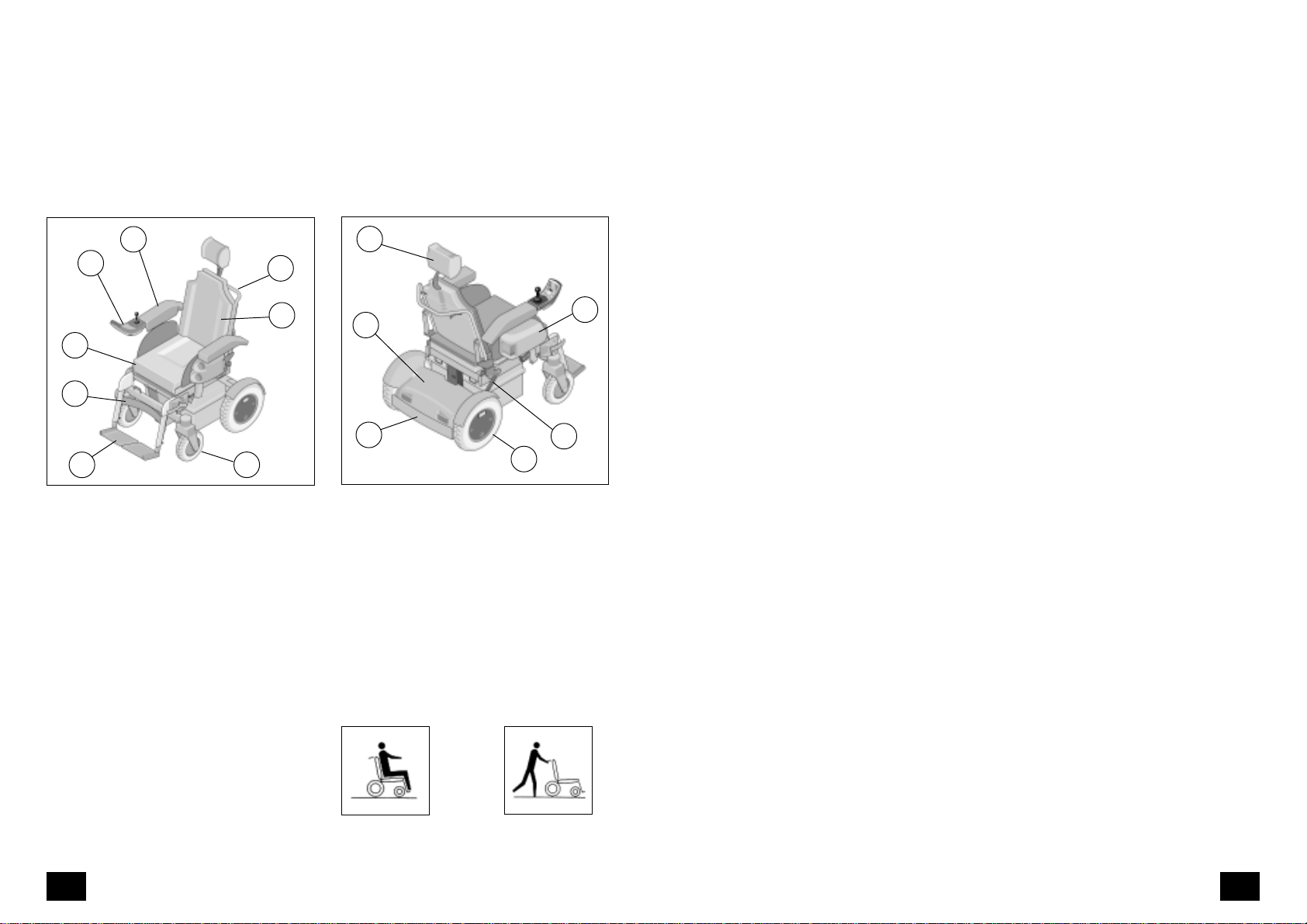
3. Overview ........................................................................................................................ 8
3.1 Model ALLROUND 970 ...................................................................................................... 8
3.1.1 Overview................................................................................................................ 8
4. Handling the wheelchair .............................................................................................. 9
4.1 Use ..................................................................................................................................... 9
4.2 Tips for accident prevention............................................................................................... 9
4.2.1 Initial driving practice ........................................................................................... 9
4.2.2 Driving on public highways ................................................................................. 10
4.2.3 Functional check ................................................................................................... 10
4.2.4 CE requirements .................................................................................................. 10
4.2.5 Safety information................................................................................................ 11
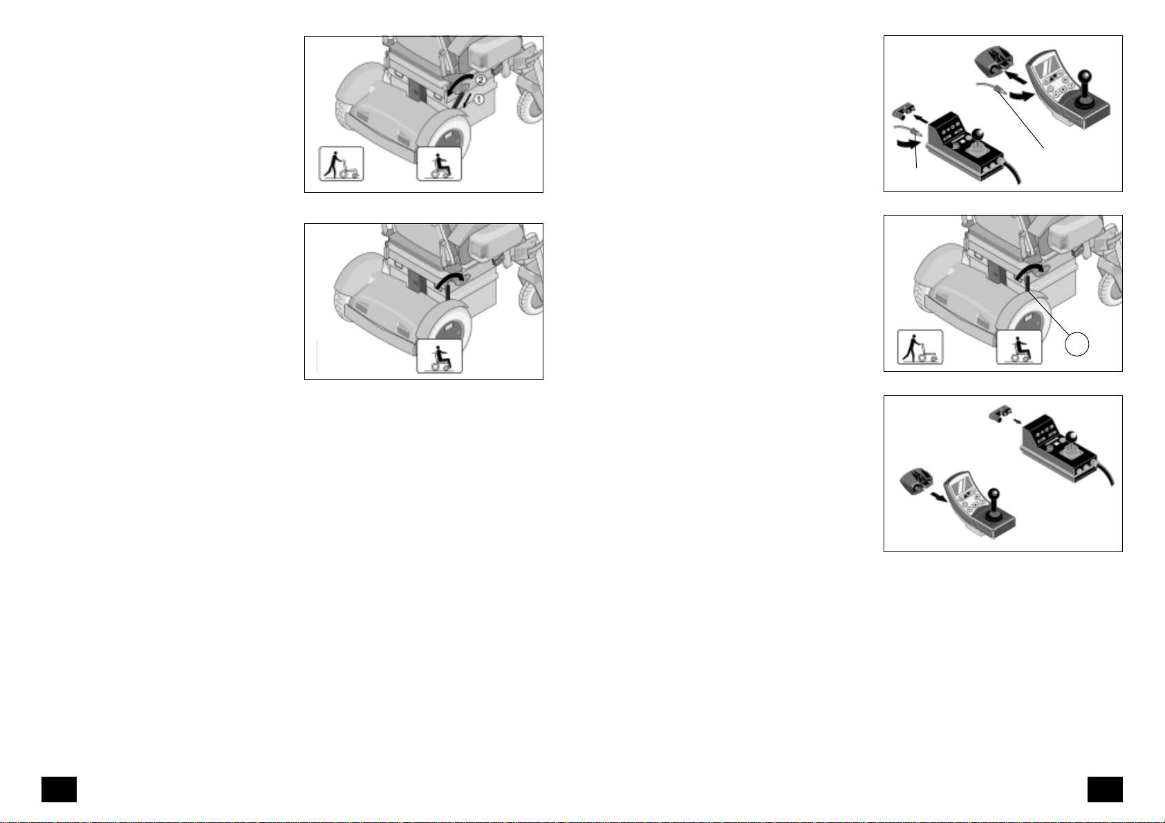
4.3 Drive/push mode..............................................................................................................12
4.3.1 Selecting the push mode ..................................................................................... 12
4.3.2 Selecting the drive mode .................................................................................... 12
4.4 Preparing for driving........................................................................................................ 13
4.4.1 Charging the battery........................................................................................... 14
4.4.2 Charging procedure ............................................................................................ 15
4.5 Driving behaviour............................................................................................................. 16
4.5.1 Safety information................................................................................................ 16
4.6 Brakes ............................................................................................................................... 17
4.6.1 Driving brake ....................................................................................................... 17
4.6.2 Parking brake....................................................................................................... 17
4.6.3 Decelerating/stopping the wheelchair................................................................ 18
4.6.4 Braking distance................................................................................................... 18
4.7 Handling the control unit ................................................................................................. 19
4.7.1 Functional description.......................................................................................... 19
4.7.2 Positioning of the control unit .............................................................................. 19
4.7.3 Detaching the control unit ................................................................................... 20
4.7.4 Attaching the control unit .................................................................................... 20
4.7.5 Swivelling the control unit to the side ................................................................. 21
4.8 Loading and transport ..................................................................................................... 21
4.8.1 Safety information................................................................................................ 21
4.8.2 Transport in vehicles............................................................................................. 22
4.8.3 Securing devices .................................................................................................. 23

54
7.7 Lighting............................................................................................................................... 61
7.7.1 Headlight............................................................................................................. 61
7.7.1.1 Removal: ............................................................................................. 61
7.7.1.2 Fitting: ................................................................................................ 61
7.7.2 Front indicator ..................................................................................................... 62
7.7.2.1 Removal: ............................................................................................. 62
7.7.2.2 Fitting: ................................................................................................ 62
7.7.3 Rear indicator ...................................................................................................... 63
7.7.3.1 Removal: ............................................................................................. 63
7.7.3.2 Fitting: ................................................................................................ 63
7.7.4 Rear light ............................................................................................................. 64
7.7.4.1 Removal: ............................................................................................. 64
7.7.4.2 Fitting: ................................................................................................ 64
7.8 Wheel change .................................................................................................................. 65
7.8.1 Disassembling the drive wheels .......................................................................... 65
7.8.1.1 Tyre change ........................................................................................ 65
7.8.2 Disassembling the swivel wheels ......................................................................... 66
7.8.2.1 Tyre change ........................................................................................ 66
7.9 Preventive maintenance (annual service) .......................................................................... 67
7.9.1 List of annual maintenance work ......................................................................... 68
7.9.2 Fault correction .................................................................................................... 69
8. Technical data ............................................................................................................. 70
8.1 Kilometric performance ................................................................................................... 70
8.1.1 Hill-climbing ability............................................................................................. 70
8.2 Fuses ................................................................................................................................. 71
8.3 Model Allround 970 ......................................................................................................... 72
8.4 Meaning of the labels on the wheelchair......................................................................... 74
9. Service record .............................................................................................................. 75
10.Guarantee .................................................................................................................... 77
Notes .................................................................................................................................. 78
6. Options .......................................................................................................................... 41
6.1 Seatbelt............................................................................................................................ 41
6.1.1 Putting on the seatbelt with Velcro fastener ....................................................... 41
6.1.2 Putting on the seatbelt with catch ...................................................................... 42
6.1.3 Opening the seatbelt .......................................................................................... 42
6.1.4 Adjusting the belt length..................................................................................... 42
6.2 Headrest........................................................................................................................... 43
6.2.1 Adjusting the headrest ........................................................................................ 43
6.3 Step climber .................................................................................................................... 44
6.3.1. Crossing an obstacle ............................................................................................ 44
6.3.1.1 Safety information .............................................................................. 45
6.3.1.2 Attaching/detaching the step climber ............................................... 45
6.4 Seat lifter.......................................................................................................................... 46
6.4.1 Safety information................................................................................................ 47
6.4.2 Operating ............................................................................................................ 47
6.4.3 User information applicable before the lifting movement.................................. 48
6.4.4 User information applicable after the lifting movement..................................... 49
6.5 Suspension, adjustable ..................................................................................................... 50
6.5.1 Adjusting the spring tension ................................................................................ 50
6.6 Anti-tip castors ................................................................................................................. 51
6.6.1 Assembly .............................................................................................................. 51
6.6.2 Disassembly ......................................................................................................... 51
7. Maintenance ................................................................................................................. 52
7.1 Cleaning........................................................................................................................... 52
7.2 Repairs.............................................................................................................................. 54
7.3 Customer service .............................................................................................................. 54
7.4 Spare parts....................................................................................................................... 54
7.4.1 Disposal................................................................................................................ 55
7.5 Batteries ........................................................................................................................... 55
7.5.1 Unsealed batteries............................................................................................... 55
7.5.2 Sealed batteries................................................................................................... 55
7.5.3 Battery charging .................................................................................................. 55
7.5.4 Battery replacement ............................................................................................ 56
7.5.5 Safety information................................................................................................ 56
7.5.6.1 Exposing the batteries........................................................................ 57
7.5.6.2 Checking the acid level: ..................................................................... 58
7.5.6.3 Measuring the acid density: ............................................................... 59
7.6 Fuses/connections ............................................................................................................. 60
7.6.1 Replacing fuses ........................................................................................................ 60
7.6.2 Fuses ..................................................................................................................... 60
7.6.3 Other connections ................................................................................................ 60

76
2. Legal require-
ments
Please comply with the legal require-
mentsofthecountryinwhichthewheel-
chair is used.
2.1 Legal requirements
for Germany
2.1.1 Electric wheelchairs with
a top speed of 6 km/h
A driving licence is not required for elec-
tric wheelchairs with a top speed of 6
km/h. Pavements may only be driven
onat walking speed. Aliability insurance
is not mandatory but recommendable.
The minimum age for driving this vehi-
cle is 15 years. An exemption certificate
for younger persons can be applied for
at the relevant administrative authority.
2.1.2 Electric wheelchairs with
a top speed of 10 km/h
Incontrasttothemodelwithatopspeed
of 6 km/h, the German traffic regula-
tions (StVZO) require the following for
the model with a top speed of 10 km/h:
▲A valid liability insurance.
▲The registration of the vehicle at the
local vehicle registration centre.
The type approval report required for
the vehicle registration is a part of the
documentationsuppliedwiththewheel-
chair. First contact your insurance com-
pany. They will provide you with an in-
surance plate that must be attached to
the rear cover of the vehicle with two
screws.
The electric wheelchair can then be tak-
en to the local vehicle registration cen-
tre. The vehicle registration centre will
checkthat the type approvalreport con-
forms with the vehicle and then stamp
it. The handling can vary from place to
place. Some registration centres do not
insist on seeing the vehicle. A telephone
call beforehand can save you an unnec-
essary journey. The vehicle can then be
drivenonpublichighwaysinaccordance
withthe German Highway Code(StVO).
You must have the type approval report
with you at all times when driving on
public highways.
☞Note:
All modifications of the vehicle inval-
idate the type approval.
1. Foreword
We thank you for the confidence you
have placed in our company by choos-
ing an electric wheelchair from the ALL-
ROUND 970 series.
The electric wheelchair can be adapted
to your individual needs by way of the
equipment variants and the accessories.
Theelectric wheelchair can beequipped
with, for example, an electrically-adjust-
able backrest and legrests.
Like every other vehicle, the electric
wheelchair is a technical aid. It needs
explanation, a small amount of mainte-
nance and can be a source of danger
when incorrectly used. The correct han-
dling must therefore be learned.
This operating manual in combination
withthe
'OperatingManualforControlUnits'
and the
'Safety Information for Electric Ve-
hicles'
brochure must be read before the
first use of the wheelchair, they are in-
tendedto help you inthe handling of the
wheelchair and to prevent accidents.
Childrenshouldreadthisoperatingman-
ual,the
'OperatingManualforControlUnits'
and the
'Safety Information for Electric Ve-
hicles'
brochuretogetherwiththeparents
or a supervising/accompanying person
before the first journey with the wheel-
chair.
☞Note:
Pleasenote that the illustratedequip-
ment variants can deviate from your
model.

98
4. Handling the
wheelchair
4.1 Use
The electric wheelchair, with attached
legrests and armrests, serves exclusive-
ly for the conveyance of one sitting per-
son. Other pulling or transporting uses
donotcomplywithitsintendedpurpose.
!Attention:
Comply with the contents of the
'Safety Information forElectricVehicles'
brochure!
The ALLROUND 970 wheelchair is in-
tended for use indoors and outdoors.
The model has been assigned the 'Use
Class B' as per the EN12184 standard.
Foroutdooron a firm surface, the wheel-
chair must be equippped with a light-
ing system.
Depending on the foot plate height
adjustment, the electric wheelchair can
cross obstacles with a max. height of 60
mm.
Higherobstaclesupto 110 mm high can
be crossed with a 'step climber'.
4.2 Tips for accident
prevention
4.2.1 Initial driving practice
A low maximum speed must be pre-se-
lected on the control unit for the initial
driving practice. Make yourself familiar
with the driving behaviour of the elec-
tric wheelchair in small steps. The elec-
tric wheelchair should not be used out-
side of the familiar environment or on
public highways before you have a safe
control of the vehicle.
3. Overview
3.1 Model ALLROUND 970
The overview (Fig. 1+2) shows the most important components and
control units.
3.1.1 Overview
➀Bumper
➁Rear cover
➂Headrest
➃Lighting unit
➄Selection lever for drive mode push
mode
➅Drive wheel
➀Foot plate
➁Calf strap
➂Seat upholstery
➃Control unit
➄Armrest
➅Push handle
➆Backrest
➇Swivel wheel
12
Push mode
Drive mode
2
1
3
4
5
6
7
8
2
3
4
5
1
6

1110
4.2.5 Safety information
▲Donotpulloutthesecurityplugwhilst
still in motion. Do not press the ON/
OFFkeywhilststillinmotion.Pressing
the key will then switch off the
electric wheelchair and cause it to
stop immediately.
▲A danger of tipping over always ex-
ists when driving with a backrest re-
clined to the rear or a seat raised at
the front: A danger of tipping over
always exists when driving with a
backrest reclined to the rear or a seat
raisedat the front.Bringthe seat into
its lower position and the backrest
into the upright position before the
start of the journey.
▲Do not adjust the seat or backrest
angle on rising/falling gradients.
– Danger of tipping over!
▲Lean the upper body forwards when
crossing an obstacle.
▲The attachment/detachment of ac-
cessories/componentsalters the driv-
ing behaviour.
▲Tyres are made of a rubber mixture
and can leave permanent or difficult-
to-remove marks on some surfaces
(e.g. plastic, wooden or parquet
flooring, carpets, mats).
▲An exposure to high temperatures
from lamps, the sun or other heat or
light sources can damage the uphol-
stery. Protect the upholstery with a
cover and/or park the wheelchair in
a protected area.
▲Never expose the electric wheelchair
to extreme weather conditions.
4.2.2 Driving on public high-
ways
The Highway Code must be complied
with when driving on public highways.
Check the functioning of the lighting
system before the start of each journey.
Carry out a short braking and steering
test at a very low speed immediately af-
ter the start of motion.
4.2.3 Functional check
The functions and safety of the electric
wheelchair must be checked before the
start of each journey.
!Attention:
Comply with the contents of
the
'Safety information for electric ve-
hicles'
brochure!
• The frame, cables and the batteries
should be checked for damage after
a collision with an obstacle. – Have
any visually identified damage re-
paired immediately by an authorised
workshop.
4.2.4 CE requirements
☞Note:
Thetechnologyof this electric wheel-
chaircomplies with the requirements
ofthe EEC 93/42 directive onelectro-
magneticcompatibility.However,the
possibility of interference from high-
frequency radiation from other elec-
trical equipment cannot be exclud-
ed.
High-frequency radiation exists in the
proximity of, for example, radar and
broadcasting stations, all types of radio
setsand radio telephones. Stopthe elec-
tric wheelchair immediately, switch off
thecontrol unit andpull out the security
plug at the front of the control unit if
the electric wheelchair reacts uncontrol-
lably due to interference or causes in-
terference to other electronic devices.
The connection of other electrical devic-
es can also cause malfunctions.
!Attention:
Never drive the electric vehicle in the
proximity of electronic medical
equipment with a high danger po-
tentialand/orlife-supportingfunction
or in the proximity of diagnostic
equipment.

1312
4.4 Preparing for driv-
ing
!Attention:
The functions and safety of the elec-
tric wheelchair must be checked be-
fore the start of each journey.
– Charge the batteries via the control
unit before the first journey (Fig. 5).
1. Switch the drive motors to the drive
mode. Do this by pushing the selec-
tionleverto the front (Fig. 6/ ➁)until
it audibly latches.
2. Plugthesecurityplug(Fig.7)intothe
control unit (at the front).
!Attention:
Do not insert any object other than
the security plug into the battery
charging socket.
– Danger of short-circuit!
– Always pull out the security plug af-
ter you have switched off the wheel-
chair with the ON/OFF key. This dis-
ables the wheelchair and prevents
an unauthorised use.
6
5
Charging plug
Charging plug
2
7
4
3
4.3 Drive/push mode
The lever (Fig. 3/ ➀) for switching the
drive motors between the drive mode
and push mode is located on the right
side of the wheelchair (optional: lever
on the left side.
!Caution:
The wheelchair should only be
switched into the push mode for
manoeuvring when it is standing on
a level surface.
Before selecting the push mode in an
emergency case and on slopes, a help-
er should hold the wheelchair in order
to stop an unwanted movement of the
wheelchair.
– The electric magnetic brakes are
switched off in the push mode. A
braking of the vehicle is then only
possible by switching back into the
drive mode.
▲Comply with the contents of the
'Safety information for electric
vehicles'
brochure.
4.3.1 Selecting the push mode
Switch off the control box because the
pushing will otherwise be made difficult
by the electric system.
1. Press down the selection lever to un-
lock the locking mechanism (Fig. 3/
➀) and then move the selection le-
ver to the rear (Fig. 3/ ➁).
Switch off the control box because the
pushing will otherwise be made difficult
by the electric system.
4.3.2 Selecting the drive mode
1. Push the selection lever to the front
(Fig. 4) uuntil it audibly latches.
2. Switch on the control box. The vehi-
cle is now ready for driving again.

1514
4.4.2 Charging procedure
The charging process for gel batteries
takes longer than that for batteries with
liquidelectrolyteduetophysicalreasons.
If the battery display indicates that the
batteryis fully charged, thiscorresponds
to 95% of nominal capacity.
1. Switch off the control unit. The se-
lection lever should be in the drive
mode position.
2. Pull out the security plug (Fig. 8).
3. Plugthebatterychargerplugintothe
battery charging socket on the con-
trol unit (Fig. 9).
4. Switch on the battery charger, re-
spectively, plug the mainsplugof the
battery charger into a convenient
mains socket. The battery is now
charging.
The charging process only runs with in-
tact main and battery fuses!
Charge preferably during the night. A
full charging of the batteries takes ap-
proximately 10 hours.
5. At the end of the charging, switch
off the battery charger, respectively
disconnect the charger from the
mains, and pull the charging plug
out of the control unit.
8
9
4.4.1 Charging the battery
The batteries should be charged imme-
diatelyaftertheuse of the electric wheel-
chair in order to have the full driving
range available at any time.
Every battery has a normal 'self-dis-
charge'. The batteries should be re-
charged once a month when the elec-
tric wheelchair is not used for a long
period of time. This keeps the electric
wheelchair ready for use.
Batteries should only be charged with a
battery charger that is suitable for the
type and rating of the batteries. The
guarantee is only preserved to its full
extent when the battery chargers sup-
pliedandrecommendedby ORTOPEDIA
are used. Your authorised dealer will be
pleased to help you choose the correct
battery charger.
Charge the batteries:
– before long tours
– before a long journey.
– whenever the use permits.
– immediately if the charge capacity
indicator is lit or blinks (see the
'Op-
eratingManualforControl Units'
).
▲Comply with the contents of the
'Safety information for electric
vehicles' brochure.
▲Observe the contents of the operat-
ing manual for the battery charger.

1716
4.6 Brakes
!Attention:
Have the brakes repaired immediate-
lybyanauthoriseddealeriftheywork
one-sided or if the braking effect is
reduced.
– Comply with the contents of the
'Safetyinformationfore electricvehicles'
brochure!
4.6.1 Driving brake
The motor works electrically as a driving
brake and decelerates the wheelchair
softly and jerk-free to a standstill.
4.6.2 Parking brake
The parking brakes only work when the
selection lever is in the drive mode posi-
tion.Theydisengageautomaticallywhen
the wheelchair starts off. They are dis-
engaged manually by moving the se-
lection lever to the push mode position.
See also section 4.3.
4.5 Driving behaviour
You determine the speed and the travel
direction through the movement of the
joystick (Fig. 10/ ➀). You can preset the
maximum speed of your wheelchair.
!Attention:
Drive especially carefully during the
first journeys!
Do this by setting the pre-selected
speed to the lowest level.
4.5.1 Safety information
!Attention:
Comply with the contents of the
op-
erating manual for CONTROL UNITS
and the
'Safety information for elec-
tric vehicles'
brochure!
– Donotpulloutthesecurityplugwhilst
still in motion. A switch-off will then
causeanabruptbrakingofthewheel-
chair.
– Comply with the max. permitted ris-
ing gradient value specified in the
'Technical data’ section.
– Startoffslowly.Carryoutashortbrak-
ing and steering test after starting
off.
10
1
– Lean the upper body forwards when
crossing an obstacle.
– Avoid jerky adjustments to driving
status when negotiating hills, trans-
verse slopes and obstacles.
– Donotget into/out of the wheelchair
unless it is switched off and the se-
lection lever has been set to drive
mode!
An unintentional contact with the
joystick can otherwise cause an un-
controlled movement of the wheel-
chair! – Danger of accidents!
– For safety reasons, use mobile tele-
phones or other radio devices only
with a switched-off wheelchair.

1918
4.7 Handling the con-
trol unit
The position of the control unit can be
adapted to the lower arm length of the
user. The control unit can also be de-
tached for transportation or storage and
can be laid on the seat or stored sepa-
rately.
!Attention:
Switch off the control unit and pull
out the security plug before adjust-
ing/detaching the control unit (Fig.
12).
4.7.1 Functional description
You will find adetaileddescription of the
keys and symbols in the
operating man-
ual for control units
.
4.7.2 Positioning of the control
unit
Slacken the clamping screw (Fig. 13/ ➀)
under the armrest by approx. one turn.
Move the control unit into the desired
position. Tighten the clamping screw
(Fig. 13/ ➀).
12
13
1
4.6.3 Decelerating/stopping the
wheelchair
The wheelchair stops when you let go
of the joystick (Fig. 11/ ➀).
Movethejoystickslowly back to the cen-
tre position (zero position) for a dosed
braking (Fig. 11/ ➀). Always ensure an
adequate braking distance when apply-
ing the wheelchair brakes.
4.6.4 Braking distance
The braking distance is dependent on
the driving surface condition and the
speed, the shortest braking distance is
approx. imately 1.0 m for the 6 km/h
version and
approx. imately 2m for the 10 km/h-
version.
!Attention:
Brake early enough when approach-
ing persons or obstacles.
11
1 2

2120
4.7.5 Swivelling the control unit
to the side
The control unit can be swivelled to the
side into a position where it is parallel to
the armrest (Fig. 16). This makes it pos-
sible to, for example, drive closer to a
table. For normal driving, swivel the
controlunit forward again overthepres-
sure point until it latches into place.
4.8 Loading and trans-
port
4.8.1 Safety information
For the transport in vehicles, you must
leave the wheelchair and sit in a suita-
ble seat in the vehicle. – The wheelchair
is not designed to withstand the forces
whichare generated inaccidents,which
exposes the user to considerable risks.
!Attention:
– Observe the
'Safety information for
electric vehicles'
.
16
4.7.3 Detaching the control
unit
Open the cable clip and slacken the
clamping screw (Fig. 15/ ➀). Push the
control unit to the rear. Slacken the
clamping screw (Fig. 15/ ➁) and pull
off the entire armrest unit in an upward
direction.
The control unit can now be pulled out
to the front. Carefully route the cable
when moving the control unit. Retight-
en the clamping screw.
4.7.4 Attaching the control unit
Insert the control unit into its clamping
device. Mount the entire armrest unit
and secure with the clamping screw.
Correctly route the connecting cable
again. Tighten the clamping screw (Fig.
15/ ➀) after having positioned the con-
trol unit.
14
15
2
1

2322
4.8.3 Securing devices
Use the front transverse tube (Fig. 21)
and the rear U-shaped securing tube for
securing the wheelchair.
▲Do not use the armrests, legrests or
push handle for lashing the wheel-
chair, use only approved an safety-
tested securing devices.
!Attention:
Switch off the control unit and then
pull out the security plug after the
loading. Move the selection lever for
the drive motors to the drive mode
position.
18
19
4.8.2 Transport in vehicles
The following items may be necessary
for the transport in vehicles (Fig. 17).
1. Taking off the legrests.
2. Detaching the control unit.
3. Detaching the armrest units.
4. Folding over or detaching the back-
rest.
The parts detached for the transport
must be carefully stowed and carefully
attached again before the next journey.
!Attention:
Do not use the wheelchair without
attached legrests and armrest units!
17

2524
4.9.1 Special safety informa-
tion:
▲For safety reasons, the wheelchair
mustbe unloaded (withoutbaggage
and without user) during its loading
into a car or when split ramps are
used.
▲Note that when driving on an in-
clined ramp the wheelchair can roll
back a short distance after coming
to a standstill and before the initial
motion (idle zone).
▲Park the car or van on level and firm
ground and engage the brake in
order to prevent the vehicle from
moving.
▲Ramps should be placed on the
groundandvehicleinsuchawaythat
they cannot slip.
▲Use only a dry, clean and undam-
aged ramp or lifting platform.
▲Position the ramps so that there is
sufficient space for steering correc-
tions with the wheelchair and no
wheel projects over the ramp edge.
▲Pre-select the lowest maximum
speed.
▲Only approved ramps or lifting plat-
forms may be used.
!Attention:
Theloading capacity perrampor lift-
ing platform must be greater than
190 kg without driver and greater
than290kgwithdriver(fixedramps)!
4.9 Ramps and lifting
platforms
The wheelchair can be loaded with the
aid of ramps or lifting platforms. The
following safety information must be
observed:
▲The
'Safetyinformationforelectricve-
hicles'.
▲The operating manual for the trans-
port vehicle.
▲The manufacturer's information for
the ramp or lifting platform.
!Attention:
The maximum bearing height spec-
ified for the ramp must be greater
than the height 'h' from the ground
to the loading surface, e.g. of the car
(Fig. 20).
20
h

2726
24
2
25
5.1.3 Swivelling up the seat
1. The seat must be swivelled up to the
rear for maintenance work and for
access to the batteries and the fuses.
!Attention:
– Park the wheelchair on a level sur-
face and move the selection lever
into the drive mode position.
– Drive down the electrically-operat-
ed seat-angle adjusting device.
– Bring the backrest into the upright
position.
–Switch off the controlunitandthen
pull out the security plug.
– Detach the legrests.
2. Lightly press down the lever under
the seat (Fig. 24/ ➀) and then swiv-
el up the seat until the locking mech-
anism latches!
☞With seat lifter and electrically-
adjustable seat angle
Detach the connecting elements
(Fig. 25/ ➁) and then swivel up the
seat until the locking mechanism
latches!
1
23
1
5. Components
5.1 Seat
5.1.1 Seat cushion
The standard seat cushion (Fig. 21) is
secured to the seat plate with Velcro fas-
teners and can be pulled off.
The ERGOpor seat cushion (Fig. 22/ ➀)
is secured to the seat shell with Velcro
fasteners and can be pulled off.
5.1.2 Adjusting the seat depth
The seat depth can be changed by
moving the backrest to a different posi-
tion.
☞Note:
The attaching must be carried out by
an authorised dealer.
The securing screws (Fig. 23/ ➀) must
be removed to reposition the backreast.
Then remove the spacer sleeves from
the holes and insert them into the holes
for the new position of the backrest
mount. Attach the backrest mount with
the securing screws.
21
22
2
1

2928
5.2 Backrest
5.2.1 Attaching/detaching the
ERGOpor backrest element
5.2.1.1 Detaching the ERGOpor
backrest element
Slacken the securing screws (Fig. 28/ ➀)
of the clamps and push them inwards.
Then push the backrest element for-
wards out of the backrest frame (Fig.
29).
5.2.1.2 Attaching the ERGOpor
backrest element
Press the backrest element, left and
right, onto the backrest frame (Fig. 29).
Push the securing screws (Fig. 28/ ➀)of
the clamps outwards and then tighten
them.
5.2.1.3 ERGOpor backrest cush-
ion
The ERGOpor backrest cushion (Fig. 30/
➁) is secured to the backrest shell with
Velcro fasteners and can be pulled off.
28
29
2
30
11
5.1.4 Swivelling down the seat
!Attention:
Carefully swivel down the seat.
– Danger of squashing between the
seat and the chassis/covers.
Open the locking device (Fig. 26/ ➁)
and press on the front edge of the seat
with one hand until the locking device
latches.
☞With seat lifter and electrically-
adjustable seat angle
Open the locking device (Fig. 26/ ➁)
and swivel down the front edge of
the seat with one hand. Attach the
connecting elements (Fig. 27/ ➂).
☞Note:
Check that the automatic locking
device has correctly latched by lift-
ing the seat unit. Danger of tipping
over!
26
2
3
27

3130
5.2.3 30° backrest
The angle of the 30° backrest (Fig. 59)
can be infinitely-adjusted between ap-
prox. -5° and 30°.
Theadjustablebackrestiscombinedwith
the sloped armrest (Fig. 33/➀) to pre-
vent a trapping between the backrest
and armrest.
5.2.3.1 Adjusting the backrest
angle
You unlock the backrest by simultane-
ously pulling both levers (Fig. 34/ ➀)on
the push bar. Then move the backrest
to the desired angle (Fig. 34/ ➁) and
release both levers. The backrest is then
locked in this position.
!Attention:
Only incline the backrest to the rear
when the wheelchair is standing on
a level surface. Danger of tipping
over when the backrest is inclined to
the rear.
33
1
34
5.2.2 Standard backrest
Tool:
1 x 13 mm open-end or ring spanner
1x hexagonal stud wrench WW 6
The angle of the standard backrest (Fig.
31/ ➀) can be infinitely adjusted be-
tween approx. 0° to 5° with the adjust-
ment screw and the lock nut.
5.2.2.1 Folding down the back-
rest
Screw far out the clamping screw (Fig.
31/ ➂) at both sides. Pull up the back-
rest and then fold it forwards.
5.2.2.2 Folding upright the back-
rest
Bring the backrest into the upright posi-
tion, then press it fully down and tight-
en the clamping screws (Fig. 31/ ➂).
31

3332
5.2.4.2 Attaching the backrest
element
Place the lateral guides onto the pins
(Fig. 38/ ➀) and then press the upper
holdersof the backrest elementontothe
frame at the left and right side.
5.2.4.3 Folding down the electric
backrest
The backrest can be folded down to the
front for storage or transport. Press
down the U-shaped bar (Fig. 39/ ➁)
and then fold down the backrest to the
front.
5.2.4.4 Folding up the electric
backrest
Pull on the push bar to bring the back-
rest into the upright position and then
pull to the rear with a jerk so that the
locking device audibly latches. - Check
for a correct locking of the locking de-
vice!
38
1
2
39
35
36
1
1
5.2.3.2 Detaching the 30° back-
rest
The 30° backrest can be detached for
transport or storage. Screw out the se-
curing screw (Fig. 35/ ➀) on both sides
and then pull off the backrest in an up-
ward direction.
5.2.3.3 Attaching the 30° back-
rest
Insert the tubes of the backrest, from
above, and then tighten the securing
screw (Fig. 36/ ➀) on both sides.
5.2.4 Electrically height-adjust-
able backrest
See the
'Operating Manual for Control
Units'
for information on how to adjust
the electrically-adjustable backrest.
5.2.4.1 Detaching the backrest
element
Pull the upper holders off the backrest
frame(Fig. 37) and thenlift off the back-
rest element in an upward direction.
37

3534
5.3.2 Height adjustment
Tool:
1 x 13 mm open-end or ring spanner
Slacken the securing screw (Fig. 42/ ➂),
bring the backrest into the desired
vertical position and then retighten the
securing screw.
!Attention:
The maximum armrest height has
been reached when the marking on
the square tube is visible.
5.3.3 Detaching the armrest
Slacken the clamping lever (Fig. 42/ ➂)
and pull off the armrest in an upward
direction.
☞Note:
The control unit must be detached
first if the armrest on the control side
is to be detached. To do this, open
the cable clip (Fig. 43/ ➃) and slack-
en the securing screw (Fig. 42/ ➀).
Pushthecontrolunitto therear.Slack-
en the clamping lever (Fig. 42/ ➂)
and pull off the entire armrest unit
in an upward direction.
42
1
43
4
3
2
The control unit can now be pulled out
to the front. Carefully route the cable
when moving the control unit. Retight-
en the clamping screw.
5.3 Armrests
The armrests can be adjusted in height
and depth to suit the needs of the user.
!Attention:
Do not use the armrests to lift or car-
ry the wheelchair.
Do not drive without the armrests!
5.3.1 Adjusting to suit the seat
depth
Tool:
1 x 13 mm open-end or ring spanner
Slacken the securing screw (Fig. 40/ ➀),
bring the armrest into the desired hori-
zontal position and then retighten the
securing screw.
☞Note:
Slacken the securing screw (Fig. 40/
➁) to adjust the depth of the control
unit. Retighten the securing screw
after the depth adjustment.
40
1 2

3736
5.5.1 Calf strap
The calf strap is hooked into the holders
of the legrests on the left and right side
(Fig. 45/ ➀).
5.5.2 Detaching the legrests
Detach the calf strap. Pull the locking
device (Fig. 46/ ➀) outwards.Swivelout
the legrest and then pull it off in an
upward direction.
5.5.6 Hanging in the legrests
With the legrest in a swivelled-out posi-
tion, hang-in the legrest (Fig. 47) and
then swivel it to the front until the lock-
ing device audibly latches. – Check for
the correct functioning of the locking
device! Attach the calf strap.
5.5.7 Adjusting the height of
the foot plate
Hold the foot plate and then unscrew
the clamping screw (Fig. 48/ ➁) by
about ½ a turn.
Movethefootplatetothedesiredheight
and then tighten the clamping screw.
!Attention:
The marking shows the maximum
extension.
45
1
46
1
47
48
2
5.4 Clothing protector
The clothing protector can be horizon-
tally displaced. You do this by slacken-
ing the securing screws (Fig 44/ ➄).
Bringing the clothing protector to the
desired position and then retightening
the securing screws.
5.5 Legrests
Various legrest models for the wheel-
chair are available. The foot plates can
be folded up to the side.
!Attention:
– Do not use the legrests to lift or
carry the wheelchair.
– Always place the feet on the foot
plates before a wheelchair motion!
44
5

3938
5.5.8.4 Adjusting the height of
the legrests
You raise the legrest to the desired height
by simply pulling it up. To lower the
legrest, hold the legrest and then press
down the lever (Fig. 52/ ➀).
5.5.8.5 Positioning the calf pad
To adjust the height, slacken the se-
curing screw (Fig. 53/ ➁), move the calf
pad up or down to the desired position
and then retighten the securing screw.
To adjust the depth,(thinor thick calf)
slackenthe securing screws (Fig.53/➂),
movethe calf padforwards or rearwards
to the desired position and then retight-
en the securing screws.
52
1
53
2
3
5.5.8 Height-adjustable legrests
774 and 774-2 AL-E
5.5.8.1 Detaching the legrests
Pull the locking device (Fig. 49/ ➀) out-
wards. Swivel out the legrest and then
pull it off in an upward direction. The
contacts will separate automatically.
5.5.8.2 Hanging in the legrests
With the legrest in a swivelled-out posi-
tion, hang-in the legrest (Fig. 50) and
then swivel it to the front until the lock-
ing device audibly latches. The contacts
make automatically. The contacts will
make automatically. – Check for the cor-
rect functioning of the locking device!
5.5.8.3 Adjusting the height of
the foot plate
Hold the foot plate and then unscrew
the clamping screw (Fig. 51/ ➁) by
about ½ a turn.
Movethefootplatetothedesiredheight
and then tighten the clamping screw.
!Attention:
The marking (crease) shows the
maximum extension.
49
1
50
51
2
Table of contents
Other Ortopedia Wheelchair manuals