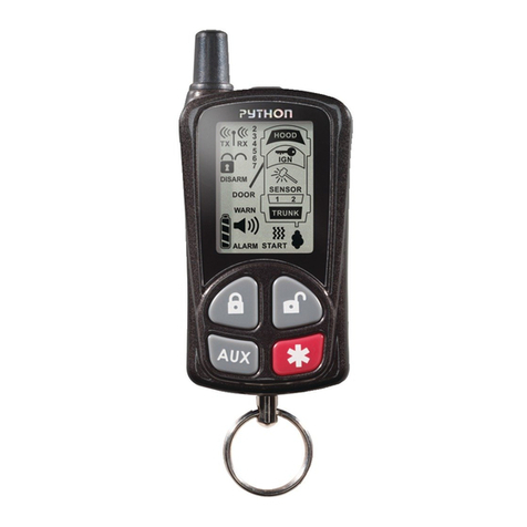
Tracker Plus User manual

RESTRICTED DOCUMENTATION
2013 Lexus IS TRACKER Plus Installation Guide
Procedure
:
MLI26A
Issue
:
1.0
Date
:
01/07/2013

TRACKER Plus for Lexus
Procedure:
MLI26A
Installation Instructions - Contents Issue: 1.0
TRACKER Network (UK) Ltd Date: 01/07/2013
TRACKER Technical Support
: 01895
455777
Contents Page
1. General Information 3
2. Installation Location 1 – TRACKER Plus 5
3. Installation Location 2 – TRACKER Plus 7

TRACKER Plus for Lexus
Procedure:
MLI26A
Installation Instructions - General Information Issue: 1.0
TRACKER Network (UK) Ltd Date: 01/07/2013
TRACKER Technical Support
: 01895
455777
General Information
(Read the following carefully before proceeding with installation)
1.1 Scope
This document describes the TRACKER Plus installation requirements of the specified vehicle.
This document MUST be used in conjunction with the other relevant TRACKER Operational
Procedures listed below.
1.2 Other References
TRACKER OP60 TRACKER SVR Installation Standards
TRACKER OP66 TRACKER Retrieve/Monitor Product Information
TRACKER OP67 TRACKER Locate Product Information
TRACKER OP68 TRACKER Locate/Plant VLU6R Commissioning
TRACKER OP85 TRACKER Dealer Portal Installer User Guide
TRACKER OP86 TRACKER Dealer Portal Sales Administrator User Guide
TRACKER TB TRACKER Technical Bulletins
1.3 Definitions
EWD Electrical Wiring Diagrams
GPS Global Positioning System
LED Light Emitting Diode
QA Quality Audit
TIS Technical Information Service
TRACKER TRACKER Network (UK) Ltd
VHF Very High Frequency
VLU Vehicle Location Unit
1.4 Holes drilled into the vehicle
Any holes drilled into the vehicle must be treated with anti-corrosion paint.
1.5 Lexus approved TRACKER units
Only approved Lexus supplied TRACKER units can be used
1.5 Airbag safety precautions
Ensure Airbag safety instructions are followed as per the Workshop Manual.
1.6 Hybrid safety precautions
Ensure Hybrid vehicle safety instructions are followed as per the Workshop Manual.
1.7 Connections to the vehicle
All connections to the vehicle MUST be made using the Lexus approved connection method as
described in TIS. Please check all connection points with the EWD for the latest wiring
information.

TRACKER Plus for Lexus
Procedure:
MLI26A
Installation Instructions - General Information Issue: 1.0
TRACKER Network (UK) Ltd Date: 01/07/2013
TRAC
KER Technical Support
: 01895
455777
1.8 Registration
Ensure the unit serial number and asset details have been correctly entered on the Dealer
Portal. (See OP85/86) Attach one VLU unit serial number barcode sticker to the vehicle job card.
1.9 Post installation
1. Ensure all wiring is free from any chafing / sharp edges. Disguise all wiring (inc. antenna) as
an existing wiring loom, using matching loom tape and/or cable ties.
2. Ensure the diagnostic LED is functioning and displays the correct sequence, If TRACKER Plus
has been installed Commission the unit. (See OP66/OP67)
3. Re-assemble vehicle.
4. Finally hand the welcome pack and remaining VLU unit serial number barcode stickers to
your Dealer Portal Sales Administrator so they can be passed on to the customer.
Kits must not be removed from the vehicle once the data has been entered onto the system and
submitted to TRACKER Network (UK) Ltd.
NOTE: Once the VLU has been connected to a permanent supply for a period of 2 hours or more, the
diagnostic LED will extinguish. The VLU will also send the network an “Out Of TEST Mode message” and
the network will respond by sending the VLU back an automatic QA.
The VLU can be reset by removing the end cap and disconnecting the internal battery for a period of
more than 30seconds, with the main 12v supply still connected. When the internal battery is
reconnected, the diagnostic LED will once again display its status for a period of 2 hours.
(See OP66/OP67)
TRACKER Plus
-
Pt No:
GBNGA
-
VU006
Qty. Description
1 Tracker
Plus Unit
(VLU6R)
1 RED 5A
Covert Fuse
1 BLUE 1A
Covert Fuse
4 Push rivets
1 Assorted
Fixing Kit
1 Welcome
Pack
Welcome Pack
Fixing Kit
TRACKER Plus unit
VLU6R

TRACKER Plus for Lexus
Procedure:
MLI26A
Installation Instructions – Lexus IS, July 2013 > Issue: 1.0
TRACKER Network (UK) Ltd Date: 01/07/2013
TRACKER Technical Support
: 01895
455777
Location 1
–
TRACKER Plus
BEFORE COMMENCING! Refer to Section:
‘General Information’
Panels to remove:
Fig. 1
Rear Seats.
Near Side rear sill trims.
Off Side rear sill trims.
Near Side “C” pillar trim.
Off Side “C” pillar trim.
Parcel Shelf.
In accordance with the Lexus Service Manual.
Mounting the TRACKER unit (VLU)
Fig. 2 – Mount the VLU in the location shown using
the supplied butyl tape or a suitable double sided
tape.
Routing the VHF antenna
Fig. 3 – Route the VHF antenna (BLACK/WHITE
wire) as shown by yellow line. Cover the wire with
looming tape, to match the vehicle’s existing
wiring harness, in order to disguise the antenna.
Ensure the VHF antenna is not secured directly to
the metal work by using a felt strip to separate
the antenna from the metalwork.
Fig. 1
Fig. 2
Fig. 3
Pull through
cable
TRACKER
Plus location
VHF Antenna
Route

TRACKER Plus for Lexus
Procedure:
MLI26A
Installation Instructions – Lexus IS, July 2013 > Issue: 1.0
TRACKER Network (UK) Ltd Date: 01/07/2013
TRACKER Technical
Support
: 01895
455777
PIN 7
Fig. 4
Fig. 5
Location 1
continued
-
Power Connections
Fig. 4 – TRACKER VLU +12v and Ignition live can
be taken from the 8 way O.E. connector plug
located at rear of Parcel Shelf, Connector plug
Q39 is for Rear Sunshade and not currently a UK
option.
Connect the BLACK wire (Earth) of the VLU, to a
local O.E. earth point using the ring terminal
supplied. Do not route the VLU Earth wire
(Black) with the VHF antenna wire (Black/White)
Fig. 5 –Connect the RED wire (+12v) of the VLU,
via the supplied RED 5A fuse assembly, to the
BLACK wire (Pin 8) of the O.E. Rear Sunshade Q39
Connector Plug.
Connect the ORANGE wire (Ign) of the VLU, via
the supplied BLUE 1A fuse assembly, to the
Black wire (Pin 7) of the rear O.E. Rear Sunshade
Q39 Connector Plug.
System testing
Complete the installation by following the
information given for ‘Post Installation’ in the
‘General Information’ on page 3 of this manual.
O.E. Plug
PIN 8

TRACKER Plus for Lexus
Procedure:
MLI26A
Installation Instructions – Lexus IS, July 2013 > Issue: 1.0
TRACKER Network (UK) Ltd Date: 01/07/2013
TRACKER Technical Support
: 01895
455777
Location
2
–
TRACKER Plus
BEFORE COMMENCING! Refer to Section:
‘General Information’
Panels to remove:
Fig. 1
Multi Display Assembly.
Glove box.
Near Side lower dash trim.
Near Side ‘A’ pillar trim.
Near Side sill trims
In accordance with the Lexus Service Manual.
Mounting the Tracker unit (VLU)
Fig. 2 – Insert the VLU towards the Near Side
through the dash where the Multi Display has been
removed, Secure the VLU using the supplied butyl
tape or a suitable double sided tape and a tie
wrap around the air vent.
Fig. 3 – When located correctly the VLU will sit
under the dash roughly in the location shown by
the yellow box. Secure the VLU using the supplied
butyl tape or a suitable double sided tape and a
tie wrap around the air vent.
Fig. 1
Fig. 2
Fig. 3

TRACKER Plus for Lexus
Procedure:
MLI26A
Installation Instructions – Lexus IS, July 2013 > Issue: 1.0
TRACKER Network (UK) Ltd Date: 01/07/2013
TRACKER Technical
Support
: 01895
455777
VHF antenna
route
Location
2 continued
-
Routing the VHF antenna
Fig. 4 – Route the VHF antenna (BLACK/WHITE
wire) as shown by yellow line, along the air vent
below the dash as indicated. Route the remainder
of the antenna wire along the Near Side “A” pillar
as indicated. Cover the wire with looming tape, to
match the vehicle’s existing wiring harness, in
order to disguise the antenna.
Ensure the VHF antenna is not secured directly to
the metal work by using a felt strip to separate
the antenna from the metalwork.
Power Connections
Fig. 5 - Connect the RED wire (+12v) of the VLU,
via the supplied RED 5A fuse assembly, to the
White wire Pin 1 of the Double Lock Door Control
K42 connector plug. (Module attached to back of
Multi Display Screen)
Connect the BLACK wire (Earth) of the VLU, to a
local O.E. earth point using the ring terminal
supplied. Do not route the VLU Earth wire
(Black) with the VHF antenna wire (Black/White)
Fig. 6 - Connect the ORANGE wire (Ign) of the
VLU, via the supplied BLUE 1A fuse assembly, to
the Beige wire PIN 24 of the Multi Display K61
connector plug.
System testing
Complete the installation by following the
information given for ‘Post Installation’ in the
‘General Information’ on page 3 of this manual.
VHF Antenna Route
Fig. 4
Fig. 6
Fig. 5
Pin 1 White wire
Pin 24 Beige wire
This manual suits for next models
1
Table of contents
