Magicar M9000 User manual

#
Installation GUIDE
M9000
By Youngshin Electronics Co., Ltd.
M9000 Controllers
Installation Guide
M9000
www.magicar.com

TABLE OF CONTENTS
2
1. Installation Tips & Recommendations
2. M-9000 Wiring Digram
3. CN 1
4.CN2
5. CN 3
6. CN 4
7. CN 5
8.CN6
9.CN7
10. CN 8
11. Transmitter Learning Routine
12. Option programming for Four Button Remotes
13. Option programming for Six Button(ONE WAY) Remotes
14. Diagnosing Problems with Auto-Start
3
5
7
9
11
16
16
16
17
17
18
19
21
23
M9000
Installation GUIDE
1

4
Installation Tips & Recommendations
3
1-1. Please be careful not to lock yourself out.
Pleaselower the glass windowsbefore you startingtheinstallationincasethe
doorlocks withthekeyinside.Also,learntheremotetothebrainmoduleafter
theinstallation hasbeencompleted.
1-2. Use Digital Multimeter for testing
Usea Digital Multimeter foralltestingofwiresinthevehicle.
Thisshould bedone onallwireseven ifyou feel thatyou know exactlywhat they
are and how they should test. Use of lamp tester may damage the electrical
circuitofthevehicle.
1-3. Find Good Ground
One of the most important wire connection is the connection to the ground.
Please findaspotthat does nothaveanyresistancetothebatteryground.
Improperground willresultinmalfunctionofthesystem.
1-4. Make sure your installation does not become a driving hazard
later to the driver.
During installation process, please try to foresee there are any potential
problemstothedriverlater.
ⓐPotential Driving Hazards
There should be no wiring around the brake.
ⓑConnection problem or Insulation problem
Please make sure all the connections are done by soldering and
properlyinsulatedbytheelectricaltapes.
ⓒWill any of your installation be affected by the vibration and
engine heat during driving?
Tiesecurely every componentsofyourinstallationby useofboltsor
cabletie.Becarefulnotto damageanywiringinsideofthe
engine compartment by the engine heat.
ⓓOrganizing wiring after the installation
Improper wiring organization will result in making noisy, connection
problems, safety hazards.
ⓔUser’s familiarity with operating manual
Installershouldexplaintheuserthoroughlyaboutthesystemoperation.
1-5. Vehicle check-up prior to and after the installation.
Foryourprotection,checkthevehicleinsideandoutincludingallofthe
vehicle operating conditions and various factory systems to make sure they
workproperlyafterinstallationinthesamemanneraspriortotheinstallation.

6
M9000 Wiring Diagram
5

8
CN1
7
No 1 (White) : (+12V)Accessory Output
Thiswirewillread
(using your digital multi-meter)
0Vwiththekeyoff,
and12Vwiththe key intheaccessoryor
‘ON’position.
TheAccessory wirewillusually dropout duringcranking.
Thiswiresupplies 12V toclimatecontrolandotheraccessoriesinthevehicle
andiscapableofsupplyingupto 30A.
Some vehicles do not have accessory wire - the ignition wire of such vehicles
supply power to the accessories.
Sodon’tconnectthisWireforsuch vehicles.
No 2 (Yellow) : (+12V)Start Motor Output
Thiswirewillread(usingyourdigitalmulti-meter)12Vwhenthekeyisinthe
crankposition.Thiswiresuppliespowertothestartermotor.
No 3 (Green) : (+12V)Ignition Output
This wirewilltest(usingyour digitalmulti-meter)0Vwiththekeyoff,and12V
withthekeyinthe‘O N or RUN ’position.
Theignitionwirewillnot dropoutduringcrankingofthevehicle.
This wire supplies 12V to the ignition coil and other electrical systems needed
forthevehicletorunproperly.
No 4 (Black) : Chassis Ground
Thiswillbetheoneofthemostimportantconnection.
Connectthiswiretobaremetalofthevehicle.
We do not recommend using the steering column for a grounding point.
Make sureyou stripback the paintoruseafactory groundingpoint.
Badgroundingonthiswirewillbethebeginningoffuturetroubles.
No 5 (Red) : (+)12V Constant
Solderthiswiretothevehicle’s12Vconstant.
This wire must be supplied power all of the time and must be able to with stand
highcurrentdraw.
No 6 (Violet) : (-)Ignition Output
1. Installation of the solenoid valve for Benz Engines
Benz Vehicle has a vacuum hose underneath of the key ignition harness.
The hose is vacuumed when engine starts with a key. To simulate this,
asolenoidhastobe installed tocreatevacuumforremotestart.
2. Propane Gas Powered Vehicles
Thereisa gasvalveswitch forsuchvehicles.Forremotestart,thisswitchhas
tobeturnedon.Therearetwodifferenttypesofswitch.

10
CN2
9
No 1, No 2 (Violet) : Positive Signal Light Output
Connectthiswiretothe(+)signallightwireonthevehicle. Thiswirewillread
(usingyourdigitalmulti-meter)eitheropenorgroundbeforethesignallight
circuit isturned onand then itwill read (+)12V after the signal light circuit is
turnedon.
No 3(Yellow) : Door Unlock Output
No 4(Green) : Door Lock Output
The following three door lock systems are the most common systems.
Relay
Diode
85
8630
87a
▼▼Method2 : SerialConnectionwiththeswitch
▼▼Method1 : ParallelConnectionwiththe switch
CN1-3
CN1-6
+12V power
Gas Valve SW
Gas Valve
87
Relay
85
8630
87a
CN1-3
CN1-6
Gas Valve SW
Cut
Gas Valve
▼▼Method1 : Negative Trigger Door Lock System (W/O Actuator)
Door Connection
CN2-3(-)
Ulock
CN2-4(-)
Lock
EXT. (Positive) INT. (Negative)
▼▼Method2 : Positive Trigger Door Lock System (W/O Actuator)
Door Switch
Factory Relay
Ulock Lock
▼▼Method3 : ExternalActuator
Door Connection
CN2-3
Ulock
CN2-4
Lock
External
Actuator
EXT. (Positive) INT. (Negative)
Door Switch
Door Connection
CN2-3(+)
Ulock
CN2-4(+)
Lock Factory Relay
Ulock
Diode
Lock
(+)12V

12
CN3
11
No 5 (White) : (+)12V Siren Output
TheBlackwire atthesirenis tobechassisgrounded.
The siren volume can be reduced by cutting the volume wire attached to the
siren.
No 6 (Black) : (+)12V Trunk Output
Ifthe vehicleisequippedwithelectricaltrunkrelease,thetrunkoutisconnected
totriggerthetrunksolenoid.
No 1 (Blue) : Negative Starter-Kill output
Pleaseusethepre-wiredstarterkillrelay.
.... Anti Grinding ...
trunk
Solenoid
trunk Release Switch
CN2-6
87
Relay
85
8630
87a
CN1-3
CN1-2
CN3-1
Cut
Start Motor
Key Holder
◀StartWire
OFF
ACC
ON
START
.... Anti Jacking ...
.... What is Noisy sensing ....
87
Relay
85
8630
87a
CN1-3 CN1-3
CN3-1
Cut
Engine
Key Holder
IgnitionWire▶
OFF
ACC
ON
START
No 2 (Yellow/Black) : Alternator sensing to monitor the engine running
Thiswireistomonitorengine running.Locate a small gauge wirefrom
the alternator. When tested with your meter, it should show you about 2V when
thekeyisonbutthevehicleisnotstarted.
When the vehicle is started using the key, the wire should read about 14V.
A. Noisy Sensing
When it is running, the engine generates sound and electrical noisy. Human
ears recognize the engine running by sound but Magicar can recognize by
electricalnoisy.Ifyouselectthenoisysetting,youdonothavetoconnectthe
alternatorsensingwire.ThefactorydefaultsettingisNoisySensing
withHighSensitivity- Switch1OffandSwitch2On.
(Starter-Kill)
(Ignition-Kill)

14
13
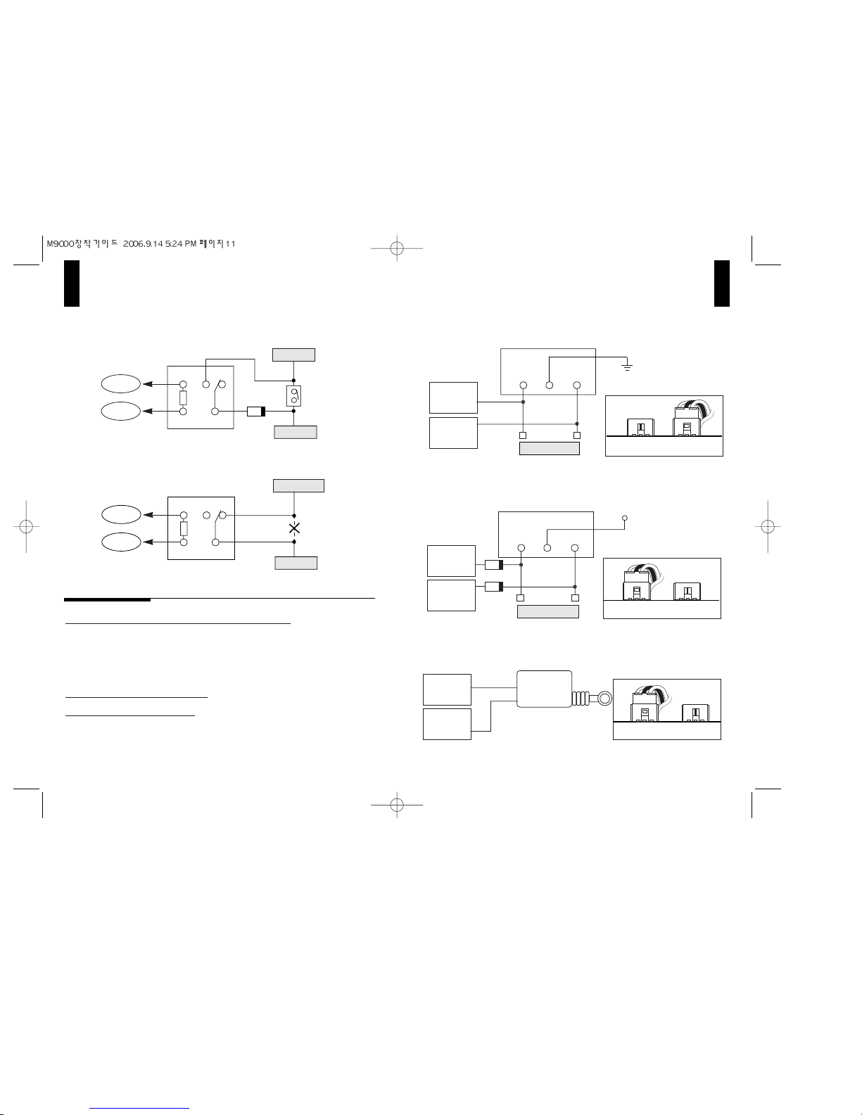
No 3 (Red/Black) : Negative Trigger Door Open Sense
No 4 (Red) : Positive Trigger Door Open Sense
Please make sure you have found a correct door sensing wire that monitors all
doors.
+12V
CN3-3(-) Door Trigger
Dome Light
Door
Trigger SW Door
Trigger SW
+12V
C N 3 -4(+) Door Trigger
Dome Light
B. Potential Problem with Noisy Sensing
Everyvehicle generatesdifferentlevelof electricalnoisy and a samevehicle
maygeneratesdifferentlevelofelectricalnoisyunderdifferentcircumstances.
Insomecases,therefore,itwillbepossiblethatMagicarthinkstheengineis
running even though only heaterfan isrunning.
C. Dip Switch Setting
●●Dip Switch #1
ON:Foravehiclethatgenerateshighlevelofelectricalnoisy.
ThissettingwillreducethesensitivityofMagicar.
OFF: For a vehicle thatgenerates low levelofelectricalnoisywhenengine
isrunning–FactorySetting.
●●Dip Switch #2
O N : Noisy Sensing –FactorySetting
OFF: AlternatorSensing
D. Noisy Sensing LED
Please find the LED inside of the cover. The LED will come on when it senses
electricalnoisybeyondpresetlevel.
E. Verifying Noisy Sensing
IfyouareselectingNoisySensing,pleaseverifyifitworksproperlyasfollows
●●Step1.Disconnect thesirenwire.
●●Step 2. Maximize the heater fan volume. Also, turn on radio and wind shield
wipers
●●Step 3. Leave the switch #1 Off, and #2 On.
●●Step4.Tryremotestarting.
a. The LED should stay off until the starter cranks and come on steady when
engine is running. Wait 2-3 minutes. If the LED stays on steady without any
blinking,youaredone.
b. If the LEDcomes on beforethe engineisrunning, shutoff theremote
starting,turnonheswitch #1and try remotestarting again.The LED should
stayoffuntilthe starter cranksandcome onsteady for the next2-3minutes
when engine is running. However, if the LED comes on again before the engine
isrunning,ortheLEDdoesnotcomeonatall,ortheLEDlightblinkstimeto
time while the engine is running, elect Alternator Sensing. Noisy Sensing does
notworkforthisvehicle.
Note 1 : For any diesel vehicles, we recommend you using Alternator
Sensing. In case you are using Noisy Sensing for a diesel vehicle, please
make sure you connect the glow plug wire.
Note 2 : Noisy Sensingwillnotworkforavehiclethathasan
alternatorproblem.

CN4
CN5
CN6
16
15
No 5 (White/Black) : Negative Glow Plug Input
No 6 (White) : Positive Glow Plug Input
If you doníftconnect one of these wires(negativeorpositiveGlowsensing),
thesystemwillactasgasolinevehicles.
Only when one of these wires are connected, your system will know the diesel
engine. The differences between gasoline and diesel engine are pre-heating
time and the running time (15minutes for gasoline engine, 25minutes for diesel
engines) when remote starting.
CN3-5
(-)Glow Plug Input
Glow Plug
Lamp
+
12V Engine
Control Module
CN3-6
(+)Glow Plug Input
Glow Plug
Lamp
Engine
Control Module
No 7 (Orange/Black) : Negative Parking Light Input
No 8 (Orange) : Positive Parking Light Input
CN 3 -7
(-)ParkingLightInput
CN 3 -8
(+)ParkingLightInput
Parking LightParkingLight
+12V Parking Light
control Relay
Parking Light
control Relay
CN 3 -9
(-)TrunkTrigger Input
Trunk Lamp
No 9 (Black) : (-)Trunk Trigger Input
Connect this wire to the trunk lamp wire as shown below.
+12V
No 1 (Black) : (-)
No 2 (Black/White) : (+)
No 1 (Black) : (-)
No 2 (Blue) : Sense
No 3 (Red) : (+)
No 1 (Black) : (-)
No 2 (White) : Sense
No 3 (Red) : (+)
No 4 (Yellow) : LED
}
Temperature Sensor
}
Shock sensor
}
Remote Pager sensor

Transmitter Learning Routine
18
17
CN7
CN8
No 1 (Yellow) : RX
No 2 (White) : TX
No 3 (Red) : (+)
No 4 (Net wire) : (-)
The antenna have been calibrated for
horizontalinstallationatthetopcornerof
thewindshield.Differentinstallationmay
affectthetransmittingdistancequiteseriously.
}
Antenna Ass y
▼Pager Location
Antenna Location▶
1 . Most vehicles
Step #1:
●Cycletheignitionkeyfromtheoff
positiontotheonpositionandback 3times
WITHIN 3 SECONDS thus giving the Green
wire(harness #1)12V 3 times.
Whenthisprocedureisdone thesignallightswillflash onetimetoconfirm
that you are in the valet/programming mode.
Step #2:
●Once in the valet/programming mode and within 6 seconds, press Button
I fora ½second.Theparkinglightswillflashonce(andtherelayinside
theControllerwillclickonce)toconfirmthatstep#2wascompleted.
Step #3:
●Pressbutton I onthenewremote toteachit totheunitwithin3seconds
of Step#2. Theunitwill accept up to 3 remotes.Each time when theunit
haslearnedaremote,the parkinglightswillflashonce(andtherelay
insidetheControllerwillclickonce)toconfirmtheprogrammingofthe
remotes.
●Ifyoulearnonly 1remote,Press button Iofoneremotefor three timesso
thatanyofthepreviouslearningisdeleted.
Ifyoulearn2remotes,pressbutton Iofthefirstremotetwotimesand
pressbutton Iof the second remote one time.
Theparkinglightswillflashtwice(andtherelayinsidewillclicktwice)to
confirm the completion of the programming.
No 1 (Yellow) : AUX 1
No 2 (Yellow/White) : AUX 2
}
AUX Output
The Various exterior devices are controlled by using of AUX output.
A selection of four output types is available with option 2-4 & 2-5.

20
19
2 . Benz types of vehicles that have vacuum hose underneath the
ignition key box.
●Follow the same steps of the above 1, except that you use button III instead
ofbutton I.
The vehicle has a programming of automatic self-unlock when you turn off the engine
with a key. So, in this case you have to choose this Bentz type option programmed
locks doors upon remote-running end. The controller generates a negative relay output
fortherelaythatcontrolsthevacuumhose.
3 . Propane Gas Powered Vehicles
●Follow the same steps of the above 1, except that you use button IV instead
ofbutton I.
Step1 :
For Programming menu 1: Key on,engine off, then Press Buttons
(I+II) for2seconds.
For Programming menu 2: Key on,engine off, then Press Buttons
(I+IV) for2seconds.Thecar will chirponceindicatingthatyou
are in programming mode.
Step2 : Within a 4 seconds afterpressing (I+II) or (I+IV),pressButton
IV the number of times to go to the option number you want to
change.
You have to hear a chirp and see the parking light
flash each time when you press Button IV.
Step3 :
Wait a few seconds. You will hear a number of chirps and see a
number of parking light flashes corresponding to the option number
youwantto change. Ifthenumber ofchirpsorflashes isnotwhat
youwant, go back to Step1.
Option Programming for Four Button Remotes
Step4 :
Press Button Iforthedefaultfactorysettingsandyourcarwill
respond by one chirp and one flash. Press Button II forthe
optional setting and yourcar willrespondbytwochirps and two
parkingflashes.
■
If you hear a long chirp, you are going out of programming mode,
please go back to Step1.
■
If you want to change more options, go back to Step1.
Resetting all of Menu #1 or Menu #2 of Programming Options to
the factory default settings - if you are not sure about current
programming, change everything to the factory settings and start
again.
1. Resetting all of Menu #1 to the factory setting
Step1:
Press buttons (I+II) simultaneouslyfor2seconds. Thiswillbe
confirmedby asirenchirpandaone-timeflashingoftheparkinglight.
Step2:
Pressbutton III once.This willbeconfirmedbyacarchirpand
parkinglightflash.Pressbutton III again. Youwill beconfirmedbya
carchirpandparkinglightflashagain. Pressbutton III thirdtime.
Youwillbeconfirmedbyacarchirpandparkinglightflashthirdtime.
Afewsecondlater,yourcarwillchirpandparkinglightflashthree
timesrapidlytoconfirmtheresetting.
2. Resetting all of Menu #2 to the factory setting.
Follow the same steps above except that you press buttons (I+
IV
)for2
seconds at the Step 1 instead of buttons (I+II).

22
21
Option Programming for Six Button(ONE WAY) Remotes
The procedures will be same as the 4 button remotes except
the use of the different buttons.
Programming
Programming Menu 1
Programming Menu 2
Option Selection
Factory Setting
Option Selection
Default Setting Selection
6 Button Remote
(Trunk+Start)-
(Trunk+Stop)-
(Stop)-
Lock
Unlock
(Start)-
4 Button Remote
(I+II)-
(I+IV)-
(IV)
( I )
( II )
( III )
Note :
1-2 Signal Light Flashing :
Withthisoption,thesignalwillflashif
any door remains open while the vehicle is disarmed.
1-4 Anti-Grinding (Starter-Kill) :
The #1 wire of CN3 can be
programmedtosendasignaltoarelay to disconnects thestarterwireof
the vehicle upon arming and upon remote-start to
prevents you from
recranking the starter on a remote - started vehicle.
Anti-Jacking (Ignition-Kill) :
The #1 wire of CN3 can be programmed
tosendasignaltoarelaytodisconnecttheignitionwireofthevehicle
upon anytimethe vehicleis armedsothat thevehicle cannotstart or run
by a remote orakey. Andtherunning of vehiclecanbe shut off by
remote’s panic command.
Programming Menu #1
Feature
Option
1
4sec
Starter Delay for Diesel vehicle
Signal-light flash when door
remains open
Duration of Door Lock Output
Application of Pre-wired
Kill Relay
Ignition Unlock
Remote Start Reservation
Cranking Time
N/A
0.8sec
Anti-Grinding
(Starter-Kill)
Anti-jacking
(Ignition-Kill)
ON
Automatic
Manual
Reservation is
not available
when any door
remains open
For Manual
only
Standard
Standard+ Min
Standard+ Max
OFF
10 sec
Activated
4sec
(Factory Default)
Button
I
Button
II
Button
III
1-1
1-2
1-3
1-4
1-5
1-6
1-7
Programming Menu #2
Feature
Option
2
Utilization
Turbo
Hour Timer Start
Remote Start Engine
Running Time
AUX 1
AUX 2
Utilization
N/U
N/U
25
Minutes
45
Minutes
5
Minutes
60 sec Latch
60 sec Latch
20 sec
0.5 sec
0.5 sec
15
Minutes
20 sec
(Factory Default)
Button I
Button II Button III Button IV
2-1
2-2
2-3
2-4
2-5
Note : 2-1, 2-2
If you want to utilize the Turbo mode and 24 Hr mode with your remote
control unit, you need to program the main module at the time of
installation.

Diagnosing Problems with Auto-Start
23
Ifthereisaprobleminauto-startingyourcar,youwillhearthreechirpswhen
youattempttoauto-startthecar.
Wait for2 secondsand thecausefor theerror willbe indicated by thenumber
of timesparkinglightsflash
Error Number
(# of times parking lights flash)
1
2
3
4
5
Error Reason
Engine On
Key On
Door Open
Trunk Open
Reservation Off
(Manual Transmission Only)
Table of contents
Other Magicar Car Alarm manuals

Magicar
Magicar M881A User manual

Magicar
Magicar FAI-440 User manual

Magicar
Magicar M871A User manual

Magicar
Magicar M870AS User manual

Magicar
Magicar M1090 User manual

Magicar
Magicar M880AS User manual

Magicar
Magicar M871A User manual

Magicar
Magicar M100AS User manual

Magicar
Magicar M881A User manual

Magicar
Magicar M902F User manual