Tracon Electric AKM1 User manual
HASZNÁLATI ÚTMUTATÓ | USER MANUAL | BEDIENUNGSANLEITUNG
INSTRUKCJA UŻYTKOWANIA | INSTRUCȚIUNI DE UTILIZARE |
KORISNIČKI PRIRUČNIK | NAVODILO ZA UPORABO | MANUALE
UTENTE | NÁVOD NA POUŽITIE | NÁVOD NA POUŽITÍ | KORISNIKI
PRIRUČNIK | MANUEL D’UTILISATION | MANUAL DE USUARIO
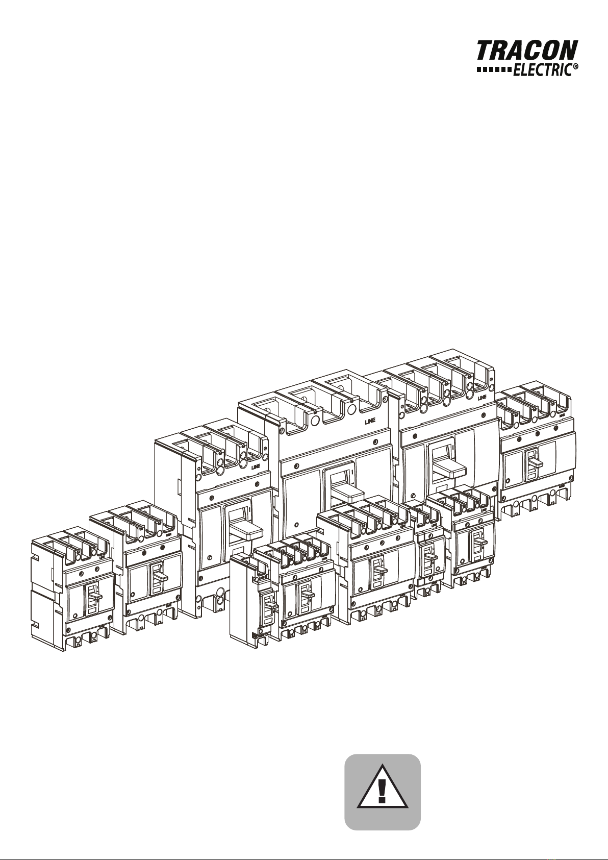
AKM
Moulded Case Circuit Breaker Product
usage manual
Only skilled or instructed persons may
carry out the following operations
Electric Current!
Danger to life!
Warning!
A K M4
-
1
1., Application
Moulded case circuit breaker is suitable for the circuit with AC 50/60HZ, rated voltage can be 690V and
below, the rated current up to 630A. Generally, if the rated current under 630A, the circuit breaker can
be used as motor protection. Normally the breakers can be used as circuit of infrequency conversion
and motor infrequently starting.
Rated current
Frame class
Fixed type
Thermomagnetic adjustable
Moulded Case Circuit Breaker
Company code
3., Circuit breaker model
2., The working environment
Temperature: -5~+40 centigrade, Average temperature cannot exceed +35 centigrade in 24 hours.
Relative humidity: the highest temperature is 40 centigrade, cannot be more than 50%, Relatively low
temperature allows relatively high humidity, such as: 20 centigrade, humidity is 80%
The altitude must not exceed 2000 meters.
Should use in a place where without explosion danger medium in the air, no corrosive action on metals
and damage insulation and without conductive dust.
Also cannot use in place where will be attacked by snow and rain, The pollution level is level 3.

UVR
UVR
2
TRIP OFF ON
TRIP -> OFF OFF -> ON ON Test button TRIPPED
A., Operation test
B., Internal accessories and installation
Auxiliary Contact
Alarm Contact
Shunt Release
Undervoltage Release

300
308
310
318
320
327
328
329
330
338
340
341
348
350
360
361
362
368
369
370
371
378
3
Accessories Table
Installation details of thermomagnetic internal accessories
Model
Undervoltage release
Shunt release (Mechanical)
Note:
Code 350, AKM2 requires customized left shunt
Alarm switch
Single auxiliary switch (1NO 1NC)
Double auxiliary switch (2NO 2NC)
Accessory
Pole
Nothing
Alarm switch
Single auxiliary switch
+ Alarm switch
Shunt release
+ Double auxiliaries switch
Two sets of double auxiliary switch
Shunt release
Double auxiliary switch
+ Alarm switch
Shunt release
+ Auxiliary alarm switch
Single auxiliary switch
+ Auxiliary alarm switch
Shunt relaease + Alarm switch
Undervoltage release
Shunt release
+ Undervoltage release
Double auxiliary switch
+ Auxiliary alarm switch
Single auxiliary switch
Undervoltage release
+ Alarm switch
Two sets of single auxiliary switch
Undervoltage release
+ Single auxiliary switch
Double auxiliary switch
Shunt release
+ Single auxiliaries switch
Single auxiliary switch
+ Double auxiliary switch
Undervoltage release
+ Double auxiliary switch
Undervoltage release
+ Auxiliary alarm switch
Left
installation
Handle
Right
installation
AKM1
3P
AKM2
3P
AKM3 / AKM4
3P

L
P1 P2
U
UC1 UC2
SHTa SHTc
ALa ALb ALc
Axc Axb Axa
ALa ALb ALc
L
P1 P2
U
UC1 UC2
SHTa SHTc
ALa ALb ALc
Axc Axb Axa
ALa ALb ALc
L
P1 P2
U
UC1 UC2
SHTa SHTc
ALa ALb ALc
Axc Axb Axa
ALa ALb ALc
4
Internal Accessories
Internal accessories of AKM1, AKM2, AKM3, and AKM4 series: undervoltage release, shunt release
and auxiliary alarm release, their main technical parameters and wiring diagram are as follows:
Undervoltage release
Rated voltage of power supply Main features
AC230
AC400
A., Undervoltage release should act
when voltage drops to within 70%
and 35% of the rated voltage.
B., The undervoltage release should not
be able to close to prevent the circuit
breaker from closing when voltage is
lower than 35% of the rated voltage.
C., The undervoltage release should en-
sure to be closed and ensure reliable
closing of the circuit breaker when
voltage is equal to or greater than
85% of the rated voltage.
Shunt release
Rated voltage of power supply Main features
DC24,
AC230, AC400
Shunt release can work reliably when the
rated voltage value is at 70% and 110%.
Auxiliary alarm contact
Rated voltage of power supply Main features
Auxiliary switch Provides distinctive signals for the circuit
breaker at „ON” and „OFF” positions.
Alarm switch
Provides distinctive signals for the circuit
breaker at „normal work” and „trip”
positions.
Auxiliary alarm switch
Provides distinctive signals for the circuit
breaker at „close”, „open” and „trip”
positions.
5
C., Internal accessories and installation
AKM1
AKM2
Attention:
(1) If an undervoltage release is used, then it
must be energized to circuit breaker can be
switched on.
(2) Undervoltage release cannot be installed with
shunt release at the same time.
(3) Shunt, undervoltage release needs to install
from the right side, auxiliaries and alarming
contact need to install from the left side.
AKM3
AKM4
(1) If an undervoltage release is used, then it must
be energized to circuit breaker can be swit-
ched on.
2) Alarming contact need to install from the left
side; auxiliaries shunt, under voltage device
can be installed both left and right.
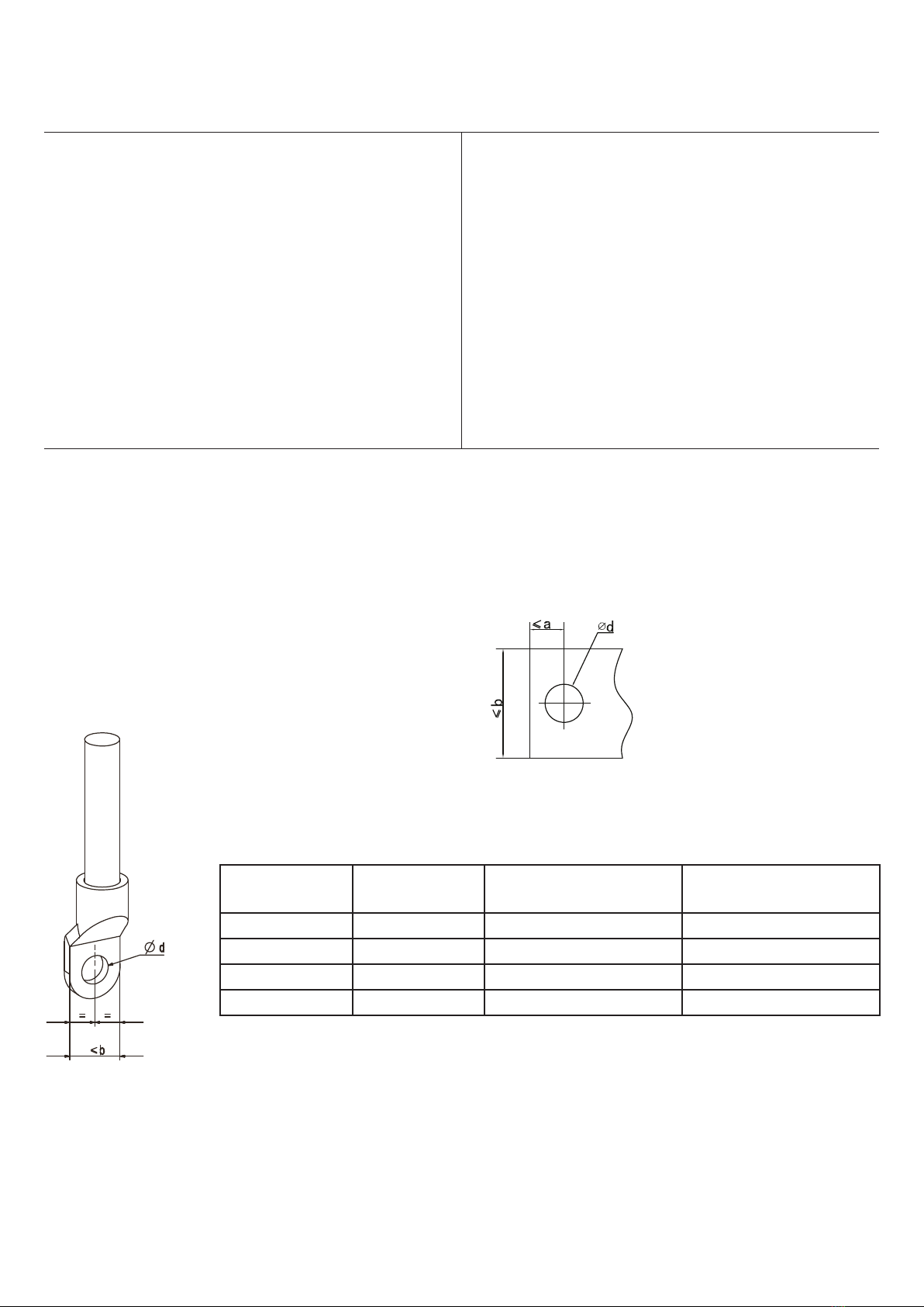
Type Width of Wiring
Terminal (mm)
Bore of Wiring
Terminal (mm)
1 AKM1 17 ∅9
2 AKM2 22 ∅9
3 AKM3 28 ∅11
4 AKM4 28 ∅11

6
D., Installation
E., Wiring
Normal-wiring

7
F., Wire connection
G., Arc shield mounting

8
CHARACTERISTICS CURVES
AKM series mechanically adjustable circuit breaker techinical description
AKM1, AKM2, AKM3, AKM4
Thermal Tripping Magnetic Tripping
Standard
IEC60947-2
No tripping
current
Tripping
current Time Holding current Trip current Time
Limits
10-63 A 1.05 ×In ≥1h 8 ×In ≥0.2 s
1.30 ×In <1h 12 ×In <0.2 s
80-630 A 1.05 ×In ≥2h 8 ×In ≥0.2 s
1.30 ×In <2h 12 ×In <0.2 s
No ln (A) Description Requirement
1
160-630
Overload long delay time release
setting current 0.8-1.0 ln Adjustable
2Short circuit instantanous release
setting current 5 In-10 In Adjustable
3
Short circuit protection
while 0.8*(5 In/10 ln),
In 0.2 s not release
4while 1.2*(5 In /10 ln),
ln 0.2 s release
Thermal
adjustable
Magnetical
adjustable

9
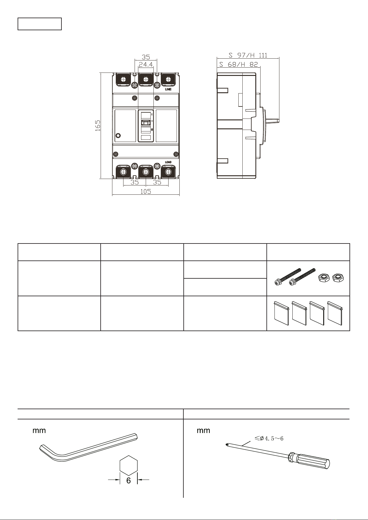
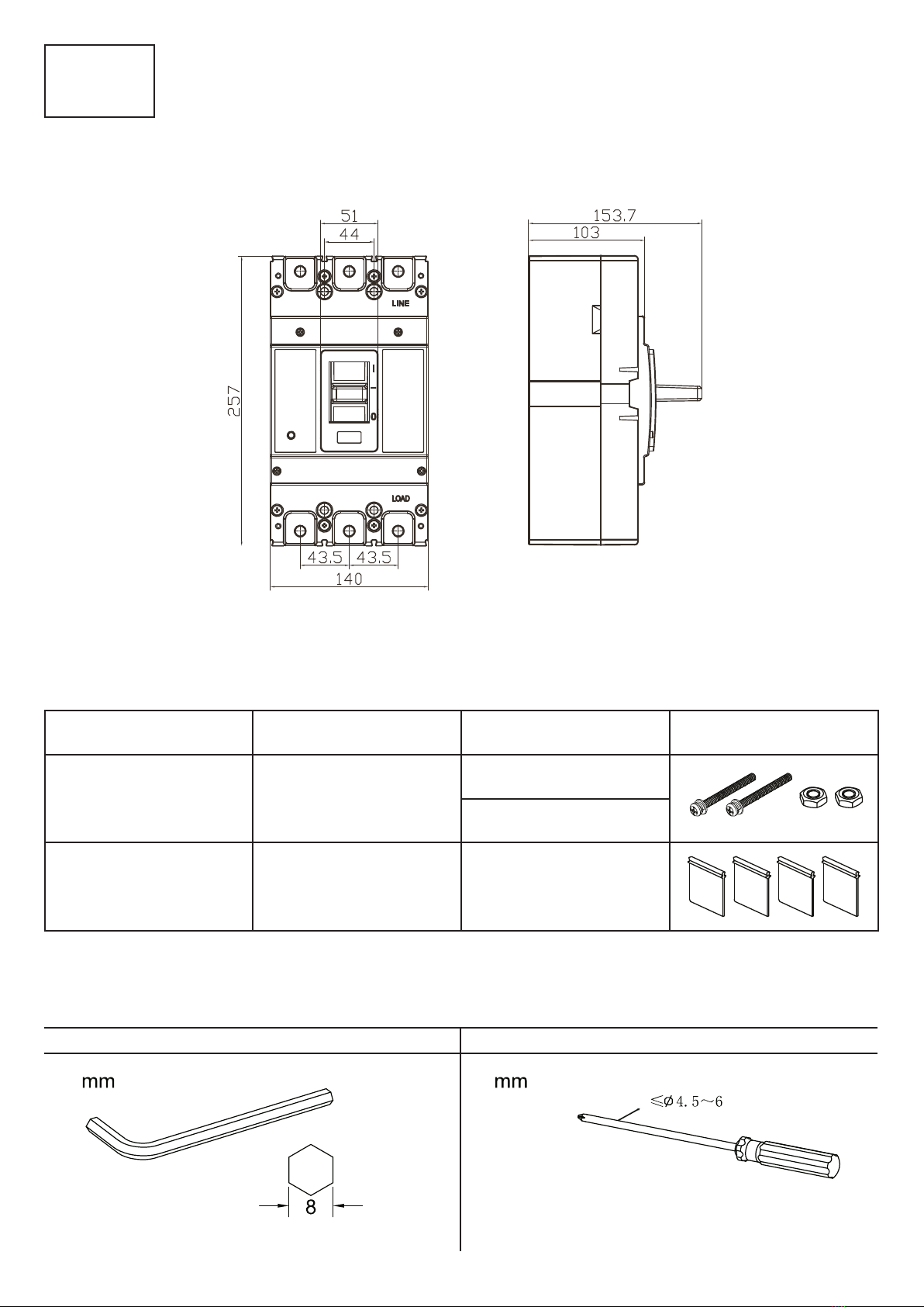
Name Size Quantity Diagram
Mounting screw M4 X 40
M4 nut bolt
3P
2
Arc shield 4
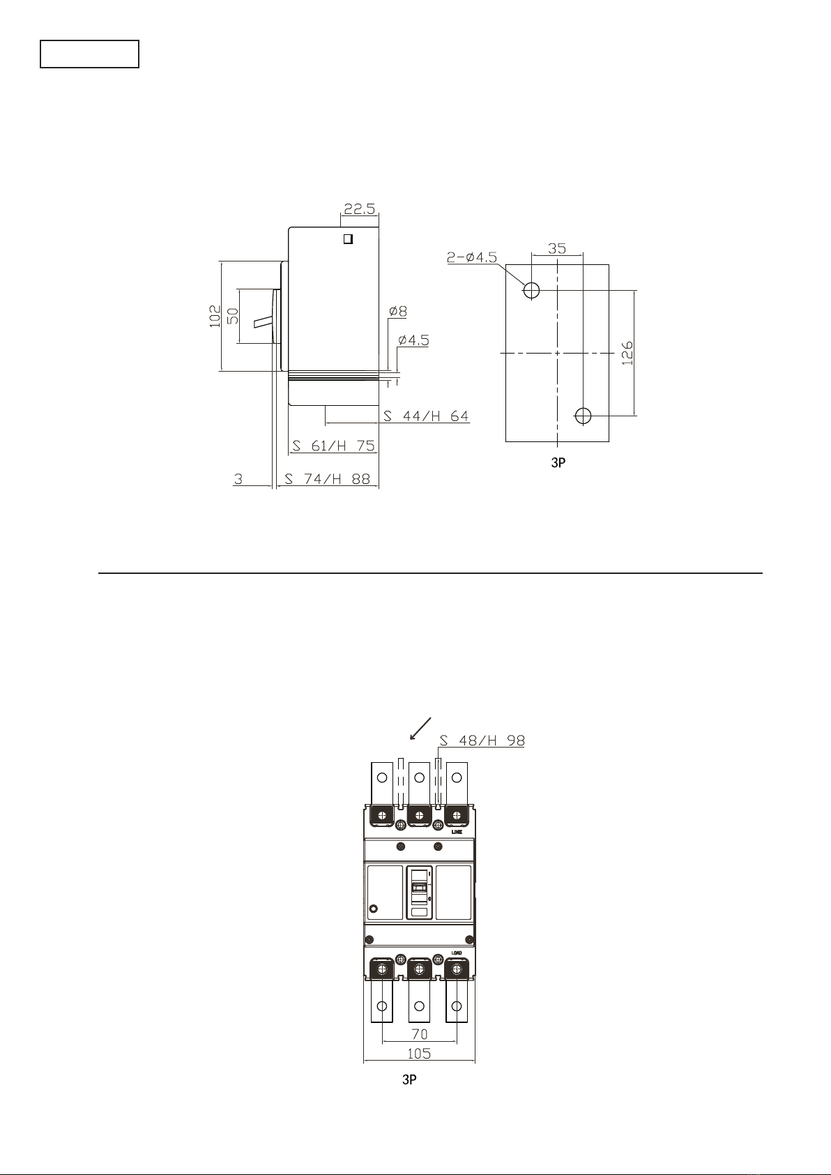
Dimensions (mm)
AKM1
Accessories
Necessary Tools
Hexagon wrench Screwdriver

10
Arc shield (removable)
Dimension of front-board wiring (mm)
Installation dimension (mm)
AKM1
11
Hexagon wrench Screwdriver
Name Size Quantity Diagram
Mounting screw
S M4 X 55
H M4 X 80
M4 nut bolt
3P
2
Arc shield 4
Dimensions (mm)
AKM2
Accessories
Necessary Tools
12
Installation dimension (mm)
AKM2
Arc shield (removable)
Dimension of front-board wiring (mm)
13
Hexagon wrench Screw driver
Name Size Quantity Diagram
Mounting screw M6 X 75
M4 nut bolt
3P
4
Arc shield 4
Dimensions (mm)
AKM3
AKM4
Accessories
Necessary tools

14
AKM3
AKM4
Installation Dimension (mm)
Arc shield (removable)
Dimension of front - board wiring (mm)

15
Installation
1. Check whether the nameplate of the circuit breaker meets the requirements before
installation. The cross section of the copper wire must match the rated rating of the
circuit breaker current.
2. All screws must be tightened during installation.
3. The cover of circuit breaker can not be opened, it’s parameters has been set and qu-
alified in the factory, please do not adjust it!
Moulded Case Circuit Breaker Standard Tripping Characteristics Test
Rated current and standard connecting wire.
Number Rated current
Standard
connecting wire
(mm
2
)
Rated current
Standard
connecting wire
(mm
2
)
1 0-8A 1.0 9-12A 1.5
2 13-15A 2.5 16-20A 2.5
3 21-25A 4.0 26-32A 6.0
4 33-50A 10.0 51-65A 16.0
5 66-85A 25.0 86-100A 35.0
6 101-115A 35.0 116-130A 50.0
7 131-150A 50.0 151-175A 70.0
8 176-200A 95.0 201-225A 95.0
9 226-250A 120.0 251-275A 150.0
10 276-300A 185.0 301-350A 185.0
11 351-400A 240.0 401-500A 2*150mm
2
12 501-630A 2*185mm
2
631-800A 2*240mm
2
13 801-1000A 2*300mm
2
1001-1250 2*400mm
2

Ez a dokumentum előzetes bejelentést nélkül megváltozhat! Naprakész információk a honlapon!
This document could be modified without notice. Updated Information on Website.
Änderungen am Dokument ohne Ankündigung möglich. Aktuelle Informationen finden Sie auf unserer Webseite.
Zastrzegamy możliwość zmiany niniejszego dokumentu bez uprzedzenia! Bieżące informacje można znaleźć na stronie internetowej!
Acest document poate fi modificat fără o notificare prealabilă! Informaţii actualizate pe pagina noastră de internet!
Ovaj dokument se može promeniti bez prethodne najave ! Aktuelne informacije možete naći na web-sajtu!
Ta dokument se lahko spremeni brez predhodnega obvestila! Posodobljene informacije najdete na spletni strani!
Questo documento può cambiare senza preavviso. Informazioni aggiornate si trovano sul sito internet.
Tento dokument sa môže zmeniť bez predchádzajúceho oznámenia! Aktuálne informácie na web-stránke!
Tento dokument může být změněn bez předchozího oznámení! Aktuální informace na web-stránce!
Ovaj dokument se može promijeniti bez prethodne najave. Važeće informacije su na web stranici.
Ce document pourrait être modifié sans préavis. Mise à jour de l’information sur le site Web
Este documento puede ser modificado sin previo aviso. Información actualizada en la página web
www.traconelectric.com
16
Use and maintenance
• Read the instruction carefully before installation and use!
• Must be used under normal working conditions!
• Before installation, make sure that the type meets the requirements or not!
• After all the wires are connected, check and then turn on the power switch!
• Circuit breakers must be properly installed and must not be abnormal mechanical
stress!
• Improper use, dropping, improper installation, external weather or natural disasters
are not warranty cases!
• Before commissioning, the circuit breaker handle must be moved up and down several
times. The structure must operate flexibly and reliably.
• In case of a general fault in the operating circuit, the circuit breaker trips and the hand-
le is in the middle position.
• If users want to close breaker after release, firstly find cause and remove the fault, pull
the handle down, in „OFF” position, then pull the handle to the „ON” position.
• The outer surface of the circuit breaker must always be cleaned of dust in order to
maintain good insulation.
This manual suits for next models
3
Table of contents
Other Tracon Electric Circuit Breaker manuals


