manuals.online logo
Brands
  1. Home
  2. •
  3. Brands
  4. •
  5. Siemens
  6. •
  7. Circuit Breaker
  8. •
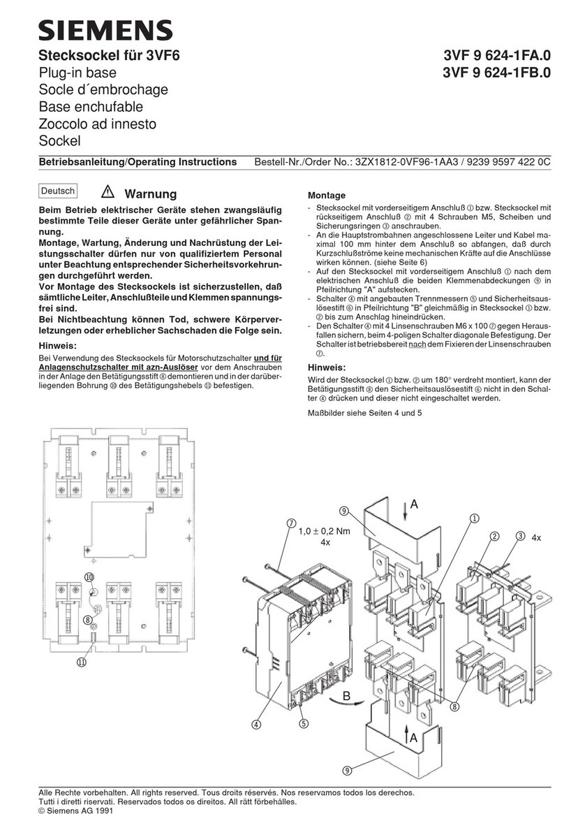
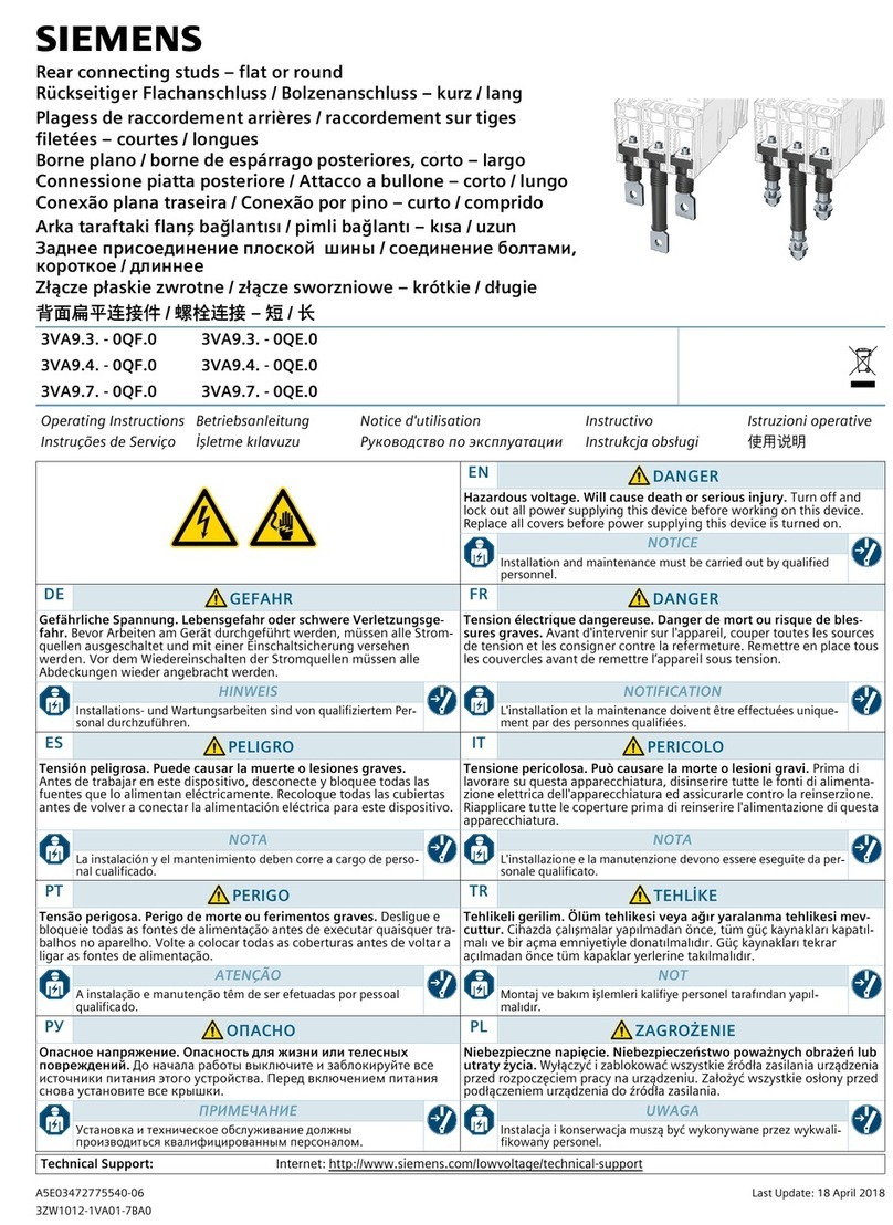
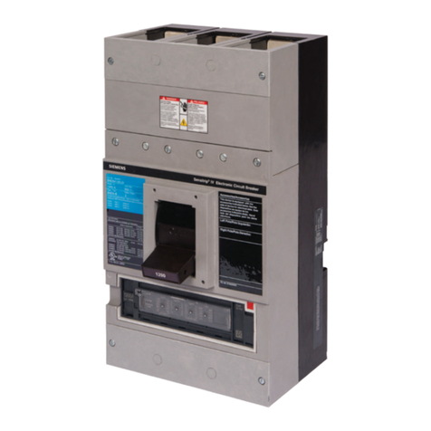
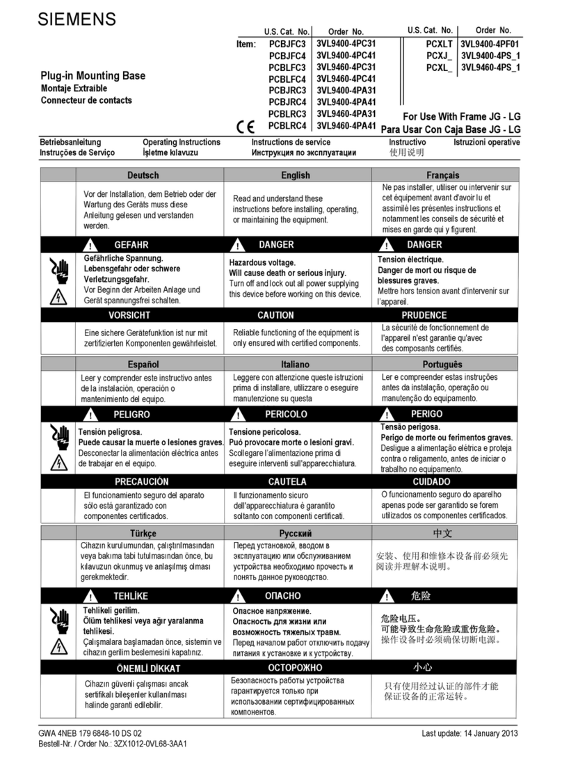
  9. Siemens Sentron WL User manual

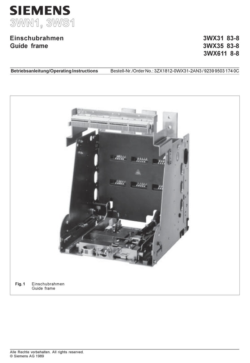
Siemens Sentron WL User manual

9239 9955 174
3ZX1812-0WL00-0AN4
Leistungsschalter
Siemens AG, Siemensstr. 10 D-93055 Regensburg
Bedienungsanleitung / Operating Instructions Bestell-Nr. / Order No.: 3ZX1812-0WL00-0AN4
GEFAHR DANGER
Gefährliche elektrische Spannung!
Kann Tod, schwere Personenschäden sowie Schäden
an Geräten und Ausrüstung bewirken.
Vor dem Arbeiten an diesem Gerät, Anlage unbedingt
spannungsfrei schalten.
Gefahr bei gespanntem Federspeicher!
Federspeicher entspannen.
Hazardous voltage!
Will cause death, serious personal injury, or equip-
ment damage.
Disconnect power before working on this equipment.
Danger if spring is charged!
Discharge spring.
s
Circuit breaker
0 – II 3ZX1812-0WL00-0AN4
0.1 Symbols0.1 Symbole
Warnhinweis Warning
Warnung vor gefährlicher, elektrischer Spannung Warning, electricity
elektrische Gefährdung Electrical Shock Hazard
Vor Arbeiten freischalten Switch off before beginning work
Warnung Kopfschutz tragen Warning, wear safety helmet
Warnung vor Handverletzungen Warning, crushing hazard: hand
autorisierte Elektrofachkraft authorized electrician
Elektrostatisch gefährdetes Gerät Electrostatic sensitive device
CE-Zeichen CE identification
Sichtprüfung Visual examination
Haken hook
Schrauben- /Steckschlüssel mit Schlüsselweite wrench with size in mm
Schlitzschraubendreher Slotted-type screwdriver
Kreuzschlitzschraubendreher
Philips (PH), PoziDriv (PZ)
Cruciform screwdriver
Philips (PH), PoziDriv (PZ)
Torx-Schraubendreher (T) Torx screwdriver (T)
Innensechskant-Schraubendreher Hexagon socket screwdriver
Anzugsdrehmoment Tightening torque 1 Nm = 0.74 ft lbf
Kabelbinder Cable tie
Handschriftlich ergänzen Add in writing
Erster Schritt einer Handlungsabfolge First step of action sequence
BK / BN / BU / GN / GY Farbcodierung nach DIN IEC 60757
Schwarz / Braun / Blau / Grün / Grau
Color code for wires according to DIN IEC 60757
Black / Brown / Blue / Green / Gray
10 Nm
1
3ZX1812-0WL00-0AN4 0 – III
0.2 Warnhinweise
%HWULHEVDQOHLWXQJ 2SHUDWLQJ,QVWUXFWLRQV ,QVWUXFWLRQVGHVHUYLFH ,QVWUXFWLYR ,VWUX]LRQLRSHUDWLYH
,QVWUXo}HVGH6HUYLoR ĮüOHWPHN×ODYX]X ǫȎȅȉǽȉǿȌȍǽȉȊȉȘȅȌȊȆȎǻȍǻȑȃȃ ,QVWUXNFMDREVãXJL ⩴倝曩䄃
'(
*()$+5
*HIlKUOLFKH6SDQQXQJ/HEHQVJHIDKURGHUVFKZHUH9HUOHW]XQJVJHIDKU
9RU%HJLQQGHU$UEHLWHQ$QODJHXQG*HUlWVSDQQXQJVIUHLVFKDOWHQ'LH,QVWDOODWLRQVXQG:DU-
WXQJVDUEHLWHQDQGLHVHP*HUlWGUIHQQXUYRQHLQHUDXWRULVLHUWHQ(OHNWURIDFKNUDIWDXVJHIKUW
ZHUGHQ
(1
'$1*(5
+D]DUGRXVYROWDJH:LOOFDXVHGHDWKRUVHULRXVLQMXU\
7XUQRIIDQGORFNRXWDOOSRZHUVXSSO\LQJWKLVGHYLFHEHIRUHZRUNLQJRQWKLVGHYLFH,QVWDOODWLRQ
DQGPDLQWHQDQFHZRUNRQWKLVGHYLFHPD\RQO\EHFDUULHGRXWE\DQDXWKRUL]HGHOHFWULFLDQ
)5
'$1*(5
7HQVLRQpOHFWULTXH'DQJHUGHPRUWRXULVTXHGHEOHVVXUHVJUDYHV
0HWWUHKRUVWHQVLRQDYDQWG·LQWHUYHQLUVXUO·DSSDUHLO/HVWUDYDX[GLQVWDOODWLRQHWGHQWUHWLHQGHFHW
DSSDUHLOGRLYHQWXQLTXHPHQWrWUHUpDOLVpVSDUXQHSHUVRQQHTXDOLILpHHQpOHFWULFLWp
(6
3(/,*52
7HQVLyQSHOLJURVD3XHGHFDXVDUODPXHUWHROHVLRQHVJUDYHV
'HVFRQHFWDUODDOLPHQWDFLyQHOpFWULFDDQWHVGHWUDEDMDUHQHOHTXLSR/DVWDUHDVGHLQVWDODFLyQ\
PDQWHQLPLHQWRGHHVWHHTXLSRVRORSXHGHOOHYDUODVDFDERXQXQHOHFWULFLVWDDXWRUL]DGR
,7
3(5,&2/2
7HQVLRQHSHULFRORVD3XzSURYRFDUHPRUWHROHVLRQLJUDYL
6FROOHJDUHO·DOLPHQWD]LRQHSULPDGLHVHJXLUHLQWHUYHQWLVXOODSSDUHFFKLDWXUD/LQVWDOOD]LRQHHOD
PDQXWHQ]LRQHGLTXHVWRDSSDUHFFKLRGHYRQRHVVHUHHIIHWWXDWLVRORGDXQHOHWWURWHFQLFRDXWRUL]-
]DWR
37
3(5,*2
7HQVmRSHULJRVD3HULJRGHPRUWHRXIHULPHQWRVJUDYHV
'HVOLJXHDDOLPHQWDomRHOpWULFDHSURWHMDFRQWUDRUHOLJDPHQWRDQWHVGHLQLFLDURWUDEDOKRQRHTXL-
SDPHQWR2VWUDEDOKRVGHLQVWDODomRHPDQXWHQomRQHVWHHTXLSDPHQWRVRPHQWHSRGHPVHUUHDO-
L]DGRVIRUHOHWULFLVWDVDXWRUL]DGRV
75
7(+/Į.(
7HKOLNHOLJHULOLPgOPWHKOLNHVLYH\DDù×U\DUDODQPDWHKOLNHVL
dDO×üPDODUDEDüODPDGDQ|QFHVLVWHPLQYHFLKD]×QJHULOLPEHVOHPHVLQLNDSDW×Q×]%XFLKD]×QPRQ-
WDM×YHEDN×P×\DOQ×]\HWNLOLELUHOHNWULNWHNQLV\HQLWDUDI×QGDQ\DS×OPDO×G×U
ǫǮ
ǩǪǛǬǨǩ
ǩȊǻȌȈȉȀȈǻȊȋȚȁȀȈȃȀǩȊǻȌȈȉȌȍȗǿȆȚȁȃȂȈȃȃȆȃǽȉȂȇȉȁȈȉȌȍȗȍȚȁȀȆȖȐȍȋǻǽȇ
ǪȀȋȀǿȈǻȒǻȆȉȇȋǻǼȉȍȉȍȅȆșȒȃȍȗȊȉǿǻȒȎȊȃȍǻȈȃȚȅȎȌȍǻȈȉǽȅȀȃȅȎȌȍȋȉȄȌȍǽȎǫǻǼȉȍȖȊȉ
ȇȉȈȍǻȁȎȃȍȀȐȈȃȒȀȌȅȉȇȎȉǼȌȆȎȁȃǽǻȈȃșǿǻȈȈȉǾȉȎȌȍȋȉȄȌȍǽǻǿȉȆȁȈȖȊȋȉȃȂǽȉǿȃȍȗȌȚȎȊȉȆ-
ȈȉȇȉȒȀȈȈȖȇȌȊȀȑȃǻȆȃȌȍȉȇȊȉȘȆȀȅȍȋȉȍȀȐȈȃȅȀ
ǫ/
=$*52ů(-
1,(
1LHEH]SLHF]QHQDSLęFLH1LHEH]SLHF]HĿVWZRSRZDŰQ\FKREUDŰHĿOXEXWUDW\Ű\FLD
3U]HGUR]SRF]ęFLHPSUDFZ\ãĉF]\þ]DVLODQLHLQVWDODFMLLXU]ĉG]HQLDHQHUJLĉHOHNWU\F]Qĉ3UDFHLQVWD-
ODF\MQHLNRQVHUZDF\MQHQDW\PXU]ĉG]HQLXPRŰHSU]HSURZDG]DþZ\ãĉF]QLHSRVLDGDMĉF\RGSRZ-
LHGQLHNZDOLILNDFMHHOHNWU\N
⤢䁼
⹦煞
⹦煞倪⺀൅⻤寲㛱峩倔⽲⹦煞㴋泂⨙⹦煞൅
㿂⩑暳㏼䃫㪺獰卣⫒⳼䂢倪䦅൅曚暳㏼兹㙾掺⾁姩㶙㣚⩑⦺寲倦ⱬ㏼⤈⤏根䌱兹倪㣚㚁㴅൅
'$
)$5(
)DUOLJVSQGLQJ/LYVIDUHHOOHUULVLNRIRUVOHPPHNYVWHOVHU
,QGHQDUEHMGHWSnEHJ\QGHVVNDODQOJJHWRJHQKHGHQJ¡UHVVSQGLQJVIUL,QVWDOODWLRQHURJYHGOL-
JHKROGHOVHUSnGHWWHDSSDUDWPnNXQJHQQHPI¡UHVDIHQDXWRULVHUHWHOHNWULNHU
),
9$$5$
9DDUDOOLQHQMlQQLWH9DNDYDORXNNDDQWXPLVYDDUDWDLKHQJHQYDDUD
/DLWHMDODLWWHLVWRRQN\WNHWWlYlMlQQLWWHHWW|PLNVLHQQHQW|LGHQDORLWWDPLVWD7lPlQODLWWHHQDVHQ-
QXVMDKXROWRW|LWlVDDVXRULWWDDDLQRDVWDDQYDOWXXWHWWXVlKN|WHNQLNNR
(7
2+7
2KWOLNSLQJH2KWHOXOHY}LUDVNHWHYLJDVWXVWHRKW
(QQHW||GHDOJXVWWXOHEVVWHHPLMDVHDGPHSLQJHYlOMDOOLWDGD6HDGPHSDLJDOGXVMDKRROGX-
VW|LGY}LEWHKDDLQXOWDWHVWHHULWXGHOHNWULN
%*
ǩǪǛǬǨǩǬǭ
ǩȊǻȌȈȉȈǻȊȋȀȁȀȈȃȀǩȊǻȌȈȉȌȍȂǻȁȃǽȉȍǻȃȆȃȉȊǻȌȈȉȌȍȉȍȍȀȁȅȃȍȀȆȀȌȈȃȊȉǽȋȀǿȃ
ǪȋȀǿȃȂǻȊȉȒǽǻȈȀȈǻȋǻǼȉȍǻȃȂȅȆșȒȀȍȀȂǻȐȋǻȈǽǻȈȀȍȉȈǻȃȈȌȍǻȆǻȑȃȚȍǻȃȆȃȎȌȍȋȉȄȌȍǽȉȍȉ
ǧȉȈȍǻȁȕȍȃȍȀȐȈȃȒȀȌȅȉȍȉȉǼȌȆȎȁǽǻȈȀȈǻȍȉǽǻȎȌȍȋȉȄȌȍǽȉȌȀȃȂǽȕȋȓǽǻȍȀǿȃȈȌȍǽȀȈȉȉȍ
ȉȍȉȋȃȂȃȋǻȈȀȆȀȅȍȋȉȍȀȐȈȃȅ
+5
23$61267
2SDVQLQDSRQ2SDVQRVWSRçLYRWLOLRSDVQRVWRGWHåNLKR]OMHGD
3ULMHSRĀHWNDUDGRYDSRVWURMHQMHLXUHđDMVSRMLWLEH]QDSRQD5DGRYHLQVWDODFLMHLRGUçDYDQMDQDXUH-
đDMXVPLMHL]YRGLWLVDPRRYODåWHQRVWUXĀQRHOHNWURWHKQLĀNRRVREOMH
0.2 Safety instructions
0 – IV 3ZX1812-0WL00-0AN4
(/ ƘƗƛ¨ƢƛƝƠ ƓƶƷƬƺƱǁƺƴǀƩƿƴƘƬƺƱǁƺƼƾưƶƮǀƴƳDžƫƫƿƼƯƮƽƼljǀƽƮǁƹƮǀƶƿƹƼlj
ƞƽƶƺƮLjǀƴƺƪƺƮƽƻƴǀDžƺƲƽưƮƿƶNJƺƮƼƹƼƺNJƺƲǀƲǀƴƺƲưƷƮǀƩƿǀƮƿƴƷƮƶǀƴƿǁƿƷƲǁƫƮLjǀƴƺ
ƮƽƼǃƫǀƩƿƴƾƝƶƲƽưƮƿƬƲƾƲưƷƮǀƩƿǀƮƿƴƾƷƮƶƿǁƺǀƫƽƴƿƴƾƮǁǀƫƾǀƴƾƿǁƿƷƲǁƫƾƽƪƲƶƺƮ
ƽƮưƹƮǀƼƼƶƼljƺǀƮƶƹLjƺƼƮLjƲƻƼǁƿƶƼƱƼǀƴƹƪƺƼƴƸƲƷǀƽƼƸLjưƼ
*$ &217Ô,57 9ROWDVFRQW~LUWHDFK%DROJREKIDLJKIHDUEiVQyWURPJKRUW~
0~FKDJXVGtFKHDQJDLOJDFKIRLQVHFXPKDFKWDDVKROiWKUDtRQQDQJDLUHDVVHRVXODQGpDQIDUREDLU
DLU,VDJOHLFWUHRLU~GDUDLWKHDPKiLQDWiFHDGDQJOpDVDVKXLWHiLODJXVREDLUFKRWKDEKiODD
GKpDQDPKDLU
/9 %Ĩ67$0, %ĩVWDPVVSULHJXPV/HWąOXVHNXYDLVPDJXWUDXPXULVNL
3LUPVX]VąNWGDUEXDWVOēG]LHWLHNąUWXXQLHUĩFLQREDURåDQDVäĩVLHUĩFHVX]VWąGĩåDQXXQWHKQLVNąV
DSNRSHVGDUEXVGUĩNVWYHLNWYLHQĩJLSLOQYDURWVHOHNWULĴLV
/7 3$92-86 3DYRMLQJDĭWDPSD3DYRMXVJ\Y\EHLDUEDVXQNDXVVXVLçDORMLPRSDYRMXV
3ULHåGDUEŨSUDGçLĉDWMXQNLWHVLVWHPRVLUSULHWDLVRĭWDPSĉäLRĭUHQJLQLRĭUHQJLPRLUWHFKQLQėV
SULHçLŠURVGDUEXVOHLGçLDPDDWOLNWLWLNĭJDOLRWDPHOHNWULNXL
07 3(5,./8 9XOWDğğSHULNROXŰ5LVNMXWD·PHZWMHZNRUULPHQWVHUMX
,WILXVDNNDULOSURYYLVWDNROOKDWDGGDZOOLWNXQTHGWIRUQLGGDZOOLOGDQLWWDJĥPLUTDEHOPD
WDĥGHPIXTGDQLWWDJĥPLU,[[RJĥOLMLHWWDLQVWDOOD]]MRQLXPDQXWHQ]MRQLIXTGDQLWWDJĥPLUMLVW-
JĥXMLWZHWWTXELVVPLQQHOHWWULčLVWDDZWRUL]]DW
1/ *(9$$5 *HYDDUOLMNHVSDQQLQJ/HYHQVJHYDDURIJHYDDUYRRUHUQVWLJOHWVHO
6FKDNHOYyyUDDQYDQJYDQGHZHUN]DDPKHGHQLQVWDOODWLHHQDSSDUDDWVSDQQLQJVYULM'HLQVWDOODWLH
HQRQGHUKRXGVZHUNHQDDQGLWWRHVWHOPRJHQHQNHOGRRUHHQJHDXWRULVVHHUGHHOHNWULFLHQXLWJHYR-
HUGZRUGHQ
52 3(5,&2/ 7HQVLXQHSHULFXORDVć3HULFROGHPRDUWHVDXGHDFFLGHQWćULJUDYH
ÍQDLQWHDvQFHSHULLOXFUćULORUGHFRQHFWDŘLLQVWDODŘLDüLDSDUDWXOGHODWHQVLXQH/XFUćULOHGHLQVWDODUH
üLvQWUHŘLQHUHSHQWUXDFHVWGLVSR]LWLYSRWILHIHFWXDWHGRDUGHFćWUHXQHOHFWULFLDQDXWRUL]DW
69 )$5$ )DUOLJVSlQQLQJ/LYVIDUDHOOHUULVNI|UDOOYDUOLJDSHUVRQVNDGRU
.RSSODDQOlJJQLQJHQRFKDSSDUDWHQVSlQQLQJVIULLQQDQGXSnE|UMDUDUEHWHQD,QVWDOODWLRQRFK
XQGHUKnOODYGHQQDDSSDUDWInUHQGDVWXWI|UDVDYHQEHK|ULJHOHNWULNHU
6. 1(%(=-
3(ÿ(16792
1HEH]SHĀQpQDSlWLH1HEH]SHĀHQVWYRRKUR]HQLDçLYRWDDOHERY]QLNXŚDçNìFK]UDQHQt
3UHG]DĀDWtPSUiF]DULDGHQLHDSUtVWURMRGSRMWHRGQDSlWLD,QåWDODĀQpD~GUçEiUVNHSUiFHQDWRPWR
SUtVWURMLP{çHY\NRQiYDŚYìOXĀQHDXWRUL]RYDQìHOHNWULNiU
6/ 1(9$51-
267
1HYDUQDQDSHWRVW1HYDUQRVW]DçLYOMHQMHDOLQHYDUQRVWKXGLKSRåNRGE
3UHG]DĀHWNRPGHODMHWUHEDSULQDSUDYLLQDSDUDWXRGNORSLWLQDSDMDQMH,QåWDODFLMVNDLQY]GUçHYDOQD
GHODQDWHMQDSUDYLVPHL]YHVWLVDPRSRREODåĀHQHOHNWULĀDU´
&6 1(%(=3(ÿÌ 1HEH]SHĀQpQDSěWt1HEH]SHĀtVPUWHOQpKRQHERWěçNpKR~UD]X
3ŒHG]DKiMHQtPSUDFtRGSRMWH]DŒt]HQtDPRGXORGQDSěWt,QVWDODĀQtD~GUçEiŒVNpSUiFHVPtQD
WRPWRSŒtVWURMLSURYiGěWSRX]HNYDOLILNRYDQìHOHNWULNiŒ´
+8 9(6=e/< 9HV]pO\HVIHV]OWVpJeOHWYHV]pO\YDJ\V~O\RVVpUOpVYHV]pO\
$PXQNiNPHJNH]GpVHHOŌWWYpJH]]HHODEHUHQGH]pVYDJ\NpV]OpNIHV]OWVpJPHQWHVtWpVpW(]HQ
D]HV]N|]|QDWHOHStWpVVHOpVDNDUEDQWDUWiVVDONDSFVRODWRVIHODGDWRNDWNL]iUyODJPHJIHOHOŌIHOKD-
WDOPD]iVVDOUHQGHONH]ŌYLOODPRVViJLV]DNHPEHUYpJH]KHWL
3ZX1812-0WL00-0AN4 0 – V
0.3 Securityhinweise
Siemens bietet Produkte und Lösungen mit Industrial Security-
Funktionen an, die den sicheren Betrieb von Anlagen, Lösun-
gen, Maschinen, Geräten und/oder Netzwerken unterstützen.
Sie sind wichtige Komponenten in einem ganzheitlichen Indu-
strial Security-Konzept. Die Produkte und Lösungen von Sie-
mens werden unter diesem Gesichtspunkt ständig
weiterentwickelt. Siemens empfiehlt, sich unbedingt regelmä-
ßig über Produkt-Updates zu informieren.
Für den sicheren Betrieb von Produkten und Lösungen von
Siemens ist es erforderlich, geeignete Schutzmaßnahmen (z.
B. Zellenschutzkonzept) zu ergreifen und jede Komponente in
ein ganzheitliches Industrial Security-Konzept zu integrieren,
das dem aktuellen Stand der Technik entspricht. Dabei sind
auch eingesetzte Produkte von anderen Herstellern zu berück-
sichtigen. Weitergehende Informationen über Industrial Secu-
rity finden Sie unter:
http://www.siemens.com/industrialsecurity
Um stets über Produkt-Updates informiert zu sein, melden Sie
sich für unseren produktspezifischen Newsletter an. Weitere
Informationen hierzu finden Sie unter
https://support.industry.siemens.com
0.4 Hinweis zum Umfang der Anleitung
Diese Bedienungsanleitung enthält aus Gründen der Übersicht-
lichkeit nicht sämtliche Detailinformationen zu allen Produktva-
rianten und kann auch nicht jeden denkbaren Fall der Aufstel-
lung, des Betriebes oder der Instandhaltung berücksichtigen.
Sollten Sie weitere Informationen wünschen, oder sollten
besondere Probleme auftreten, die in der Bedienungsanleitung
nicht ausführlich genug behandelt werden, können Sie die
erforderliche Auskunft über die örtliche Siemens-Niederlassung
anfordern.
Außerdem weisen wir darauf hin, dass der Inhalt dieser Bedie-
nungsanleitung nicht Teil einer früheren oder bestehenden Ver-
einbarung, Zusage oder eines Rechtsverhältnisses ist oder
dieses abändern soll. Sämtliche Verpflichtungen von Siemens
ergeben sich aus dem jeweiligen Kaufvertrag, der auch die voll-
ständige und alleingültige Gewährleistungsregelung enthält.
Diese vertraglichen Gewährleistungsbestimmungen werden
durch die Ausführung dieser Bedienungsanleitung weder erwei-
tert noch beschränkt.
SENTRON® ist eine eingetragene Marke der Siemens AG. Die übri-
gen Bezeichnungen in dieser Dokumentation können Marken sein,
deren Benutzung durch Dritte für deren Zwecke die Rechte der
Inhaber verletzt.
VORSICHT CAUTION
Zum Schutz der elektrostatisch gefährdeten Bauele-
mente (EGB) ist der Schalter, anzuschließende Geräte
und das Bedienpersonal auf das gleiche Potenzial zu
bringen.
To protect the electrostatic sensitive devices (ESD) the
circuit breaker, equipment to be connected, and also
operating personnel, need to be at the same potential.
0.3 Security information
Siemens provides products and solutions with industrial secu-
rity functions that support the secure operation of plants, soluti-
ons, machines, equipment and/or networks. They are important
components in a holistic industrial security concept. With this
in mind, Siemens’ products and solutions undergo continuous
development. Siemens recommends strongly that you regularly
check for product updates.
For the secure operation of Siemens products and solutions, it
is necessary to take suitable preventive action (e.g. cell protec-
tion concept) and integrate each component into a holistic,
state-of-the-art industrial security concept. Third-party pro-
ducts that may be in use should also be considered. For more
information about industrial security, visit:
http://www.siemens.com/industrialsecurity
To stay informed about product updates as they occur, sign up
for a product-specific newsletter. For more information, visit
https://support.industry.siemens.com
0.4 Note regarding the manuals scope
For reasons of clarity, these instructions do not cover all details
or variations in equipment, nor do they provide for every pos-
sible contingency to be met in connection with installation, ope-
ration or maintenance.
Should further information be desired or should particular pro-
blems arise which are not covered sufficiently for the Purcha-
ser’s purposes, the matter should be referred to the local
Siemens Sales Office.
The contents of this instruction manual shall not became part or
modify any prior or existing agreement, commitment or relati-
onship. The sales contract contains the entire obligations of
Siemens. The warranty contained in the contract between the
parties in the sole warranty of Siemens. Any statements contai-
ned herein do not create new warranties or modify the existing
warranty.
SENTRON® is a trade-mark of Siemens AG. The other designati-
ons in this documentation can be trademarks. Use by third parties
for their own purposes violates the owner's rights.
0 – VI 3ZX1812-0WL00-0AN4
0.5 Inhaltsverzeichnis
Symbole 0- II
Warnhinweise 0- III
Securityhinweise 0- V
Hinweis zum Umfang der Anleitung 0- V
Inhaltsverzeichnis 0- VI
1Aufbau 1-1
Leistungsschalter 1- 1
Einschubrahmen 1- 2
2Schilder 2-1
Ausstattungsschild Leistungsschalter 2- 1
Schild Bemessungsnennstrommodul 2- 1
Typschild Leistungsschalter 2- 2
Typschild Einschubrahmen 2- 2
3 Normen, Bestimmungen 3- 1
Normen 3- 1
4 Transport 4- 1
Überseeverpackung 4- 1
Auspacken 4- 1
Transport mit Kran 4- 2
5Montage 5-1
Einbau 5- 1
Einbaulage 5- 1
Einbau auf waagerechter Ebene 5- 2
Einbau an senkrechter Ebene mit Tragwinkel 5- 2
Anschluss-Schienen 5- 4
Horizontalanschluss 5- 4
Flanschanschluss (nur Einschubrahmen) 5- 4
Frontanschluss 5- 5
Festeinbauschalter 5- 5
Einschubrahmen 5- 6
Vertikalanschluss 5- 7
Festeinbauschalter 5- 7
Einschubrahmen 5- 8
Zulässige Anschluss-Schienenvarianten für
Baugröße I 1000 V DC Leistungstrennschalter 5- 10
Zulässige Verschaltungen, Schaltpläne für
Baugröße I 1000 V DC Leistungstrennschalter 5- 10
Bestellnummern 5- 11
Hauptleiter anschließen 5- 13
Hauptleiteranschluss säubern 5- 13
Kupfer-Anlagenschienen säubern 5- 13
Anlagenseitige Schienen festschrauben 5- 13
Hauptleiter abstützen 5- 14
Hilfsleiteranschlüsse 5- 15
Querschnitte 5- 15
Messerleiste 5- 16
Anordnung 5- 16
Nachrüsten 5- 16
Leitungen anschließen 5- 17
Schleifkontaktmodul 5- 17
Nachrüsten 5- 17
Hilfsstromstecker 5- 18
Ausführungen 5- 18
Nur Festeinbauschalter:
Führungszungen anbringen 5- 18
Nur Festeinbauschalter
Kodierung Hilfsstromstecker - Messerleiste 5- 19
Hilfsstromstecker aufsetzen 5- 19
0.5 Table of contents
Symbols 0- II
Safety instructions 0- III
Security information 0- V
Note regarding the manuals scope 0- V
Table of contents 0- VI
1 Design 1- 1
Circuit breaker 1- 1
Guide frame 1- 2
2 Labels 2- 1
Circuit breaker options label 2- 1
Rating plug label 2- 1
Type label circuit breaker 2- 2
Type label guide frame 2- 2
3 Standard specifications 3- 1
Standards 3- 1
4 Transport 4- 1
Overseas packing 4- 1
Unpacking 4- 1
Lifting by crane 4- 2
5 Installation 5- 1
Mounting 5- 1
Mounting position 5- 1
Mounting on horizontal surface 5- 2
Mounting to vertical surface with mounting angles 5- 2
Connecting bars 5- 4
Horizontal connection 5- 4
Flange connection (guide frame only) 5- 4
Front connection 5- 5
Fixed-mounted breaker 5- 5
Guide frame 5- 6
Vertical connection 5- 7
Fixed-mounted breaker 5- 7
Guide frame 5- 8
Permissible connection bar versions for frame
size I 1000 V DC non-automatic air circuit breaker 5- 10
Permissible connections, connection schemes for frame
size I 1000 V DC non-automatic air circuit breaker 5- 10
Order numbers 5- 11
Connecting the main conductors 5- 13
Cleaning the main conductor connection 5- 13
Cleaning the copper bars 5- 13
Bolt tight line-side bars 5- 13
Bracing the main conductors 5- 14
Auxiliary conductors 5- 15
Cross sections 5- 15
Receptacle 5- 16
Arrangement 5- 16
Retrofitting 5- 16
Connecting secondary wiring 5- 17
Sliding contact module 5- 17
Retrofitting 5- 17
Auxiliary connectors 5- 18
Versions 5- 18
Fixed-mounted breaker only:
mounting of guide tongues 5- 18
Fixed-mounted breaker only
Coding auxiliary connectors 5- 19
Mounting secondary disconnects 5- 19
3ZX1812-0WL00-0AN4 0 – VII
Impermissible area for wires 5- 20
Wiring in guide frame 5- 20
Arrangement of secondary disconnects 5- 21
Order numbers 5- 21
Connecting the grounding conductor 5- 22
Fixed-mounted breaker 5- 22
Guide frame 5- 22
Ground protection between guide frame and
draw-out circuit breaker 5- 23
Retrofitting 5- 23
Lubrication of contact 5- 24
Order numbers / Z-option 5- 24
Converting fixed-mounted circuit breakers
into draw-out circuit breakers 5- 25
Conversion 5- 25
Updating the labels 5- 27
Order numbers / Z-option 5- 28
6 Commissioning 6- 1
Preparation of draw-out circuit breaker 6- 1
Inserting the circuit breaker in the guide frame 6- 1
Positions of the breaker in the guide frame 6- 2
Unlocking the racking handle /
Withdrawing racking handle 6- 3
Racking circuit breaker into the connected position 6- 3
Push in the racking handle 6- 3
Charging the spring storage 6- 4
Charging manually 6- 4
Charging with a motor operating mechanism 6- 4
Checklist for commissioning 6- 5
Closing 6- 6
Switching off 6- 6
Tripping by overcurrent release 6- 7
Reclosing a circuit breaker tripped by the
trip unit 6- 7
Putting out of service 6- 9
Troubleshooting 6- 12
7 Frame sizes and dimension drawings
for 3WL1 7- 1
Frame size I, fixed-mounted version,
3-pole and 4-pole 7- 1
Standard version, horizontal connection 7- 1
Vertical connection 7- 1
Front connection (single hole) 7- 2
Front connection (double hole) 7- 2
Terminal dimensions 7- 2
Safety distances 7- 2
Frame size I, withdrawable version,
3-pole and 4-pole 7- 3
Standard version, horizontal connection 7- 3
Flange connection 7- 3
Vertical connection 7- 3
Front connection (single hole) 7- 4
Front connection (double hole) 7- 4
Terminal dimensions 7- 4
Safety distances 7- 4
Frame size II, fixed-mounted version,
3-pole and 4-pole 7- 5
Standard version, horizontal connection 7- 5
Vertical connection up to 3200 A AC and 4000 A DC 7- 5
Vertical connection up to 4000 A AC 7- 5
Front connection (single hole) 7- 6
Front connection (double hole) 7- 6
Terminal dimensions 7- 6
Safety distances 7- 6
Unzulässige Bereiche für Leitungen 5- 20
Leitungsverlegung am Einschubrahmen 5- 20
Bestückung mit Hilfsleiteranschlüssen 5- 21
Bestellnummern 5- 21
Schutzleiter anschließen 5- 22
Festeinbauschalter 5- 22
Einschubrahmen 5- 22
Erdschutz zwischen Einschubrahmen und
Einschubschalter 5- 23
Nachrüsten 5- 23
Kontakt fetten 5- 24
Bestellnummern / Z-Zusatz 5- 24
Umrüsten Festeinbauschalter in
Einschubschalter 5- 25
Umrüsten 5- 25
Schilder aktualisieren 5- 27
Bestellnummern / Z-Zusatz 5- 28
6 Inbetriebnahme 6- 1
Vorbereitung des Einschubschalters 6- 1
Schalter in Einschubrahmen einsetzen 6- 1
Positionen des Schalters im Einschubrahmen 6- 2
Handkurbelsperre lösen /
Handkurbel herausziehen 6- 3
Schalter in Betriebsstellung verfahren 6- 3
Handkurbel einschieben 6- 3
Federspeicher spannen 6- 4
Spannen per Hand 6- 4
Spannen durch Motorantrieb 6- 4
Checkliste für Inbetriebnahme 6- 5
Einschalten 6- 6
Ausschalten 6- 6
Auslösen durch Überstromauslöser 6- 7
Wiederinbetriebnahme nach Auslösung
durch Überstromauslöser 6- 7
Außerbetriebnahme 6- 9
Störungsbeseitigung 6- 10
7 Baugrößen und Maßbilder
für 3WL1 7- 1
Baugröße I, Festeinbau,
3- und 4-polig 7- 1
Standardausführung Horizontalanschluss 7- 1
Vertikalanschluss 7- 1
Frontanschluss (einfach) 7- 2
Frontanschluss (Doppelloch) 7- 2
Anschlussmaße 7- 2
Sicherheitsabstände 7- 2
Baugröße I, Einschubausführung,
3- und 4-polig 7- 3
Standardausführung Horizontalanschluss 7- 3
Flanschanschluss 7- 3
Vertikalanschluss 7- 3
Frontanschluss (einfach) 7- 4
Frontanschluss (Doppelloch) 7- 4
Anschlussmaße 7- 4
Sicherheitsabstände 7- 4
Baugröße II, Festeinbau,
3- und 4-polig 7- 5
Standardausführung Horizontalanschluss 7- 5
Vertikalanschluss bis 3200 A AC und 4000 A DC 7- 5
Vertikalanschluss bis 4000 A AC 7- 5
Frontanschluss (einfach) 7- 6
Frontanschluss (Doppelloch) 7- 6
Anschlussmaße 7- 6
Sicherheitsabstände 7- 6
0 – VIII 3ZX1812-0WL00-0AN4
Baugröße II, Einschubausführung,
3- und 4-polig 7- 7
Standardausführung Horizontalanschluss 7- 7
Vertikalanschluss bis 3200 A AC und 4000 A DC 7- 7
Vertikalanschluss bis 4000 A AC 7- 7
Frontanschluss (einfach) 7- 8
Frontanschluss (Doppelloch) 7- 8
Flanschanschluss 7- 8
Anschlussmaße 7- 8
Sicherheitsabstände 7-
8
Baugröße III, Festeinbau,
3- und 4-polig 7- 9
Standardausführung Horizontalanschluss 7- 9
Vertikalanschluss 7- 9
Frontanschluss (einfach) 7- 10
Frontanschluss (Doppelloch) 7- 10
Anschlussmaße 7- 10
Sicherheitsabstände
7- 10
Baugröße III, Einschubausführung,
3- und 4-polig 7- 11
Standardausführung Horizontalanschluss 7- 11
Vertikalanschluss, bis 6300 A 7- 11
Flanschanschluss, bis 4000 A 7- 11
Frontanschluss (einfach) 7- 12
Frontanschluss (Doppelloch) 7- 12
Anschlussmaße 7- 12
Sicherheitsabstände 7- 12
Externer Wandler für Neutralleiter 7- 13
Baugröße I 7- 13
Baugröße II 7- 13
Baugröße III 7- 13
Spannungswandler 7- 13
Weitere Maßbilder 7- 13
8 Schaltpläne 8- 1
Klemmenbelegung Zubehör 8- 1
Hilfsstromschalter 8- 3
Meldeschalter
8- 4
Hilfsauslöser / Elektrische Einschaltsperre 8- 5
Einschaltmagnet / Elektrisch EIN 8- 5
Motorantrieb 8- 6
Fernrücksetzmagnet 8- 6
Schutzkreise für ETU45B - ETU76B 8- 7
Mit Breaker Status Sensor (BSS)
und Messmodul 8- 7
Nur mit Messmodul 8- 8
Nur mit Breaker Status Sensor (BSS) 8- 8
9 Elektronische Ausrüstung 9- 1
Überstromauslöser 9- 1
Funktionsübersicht 9- 1
Überstromauslöser ETU15B 9- 3
Ansicht 9- 3
Einstellen des Überstromschutzes 9- 4
Schutzfunktionen 9- 4
Kennlinien 9- 5
Überstromauslöser ETU25B 9- 6
Ansicht 9- 6
Einstellen des Überstromschutzes 9- 7
Schutzfunktionen 9- 7
Kennlinien 9- 8
Überstromauslöser ETU27B 9- 9
Ansicht 9- 9
Einstellen des Überstromschutzes 9- 10
Schutzfunktionen 9- 10
Kennlinien 9- 11
Frame size II, withdrawable version,
3-pole and 4-pole 7- 7
Standard version, horizontal connection 7- 7
Vertical connection up to 3200 A AC and 4000 A DC 7- 7
Vertical connection up to 4000 A AC 7- 7
Front connection (single hole) 7- 8
Front connection (double hole) 7- 8
Flange connection 7- 8
Terminal dimensions 7- 8
Safety distances 7- 8
Frame size III, fixed-mounted version,
3-pole and 4-pole 7- 9
Standard version, horizontal connection 7- 9
Vertical connection 7- 9
Front connection (single hole) 7- 10
Front connection (double hole) 7- 10
Terminal dimensions 7- 10
Safety distances 7- 10
Frame size III, withdrawable version,
3-pole and 4-pole 7- 11
Standard version, horizontal connection 7- 11
Vertical connection, up to 6300 A 7- 11
Flange connection, up to 4000 A 7- 11
Front connection (single hole) 7- 12
Front connection (double hole) 7- 12
Terminal dimensions 7- 12
Safety distances 7- 12
External transformer for neutral 7- 13
Frame size I 7- 13
Frame size II 7- 13
Frame size III 7- 13
Voltage transformer 7- 13
Further dimension drawings 7- 13
8 Circuit diagrams 8- 1
Terminal assignment accessory 8- 1
Auxiliary switches 8- 3
Signaling switches 8- 4
Auxiliary releases / Electrical closing lockout 8- 5
Closing coil / Electrical ON 8- 5
Motor operating mechanism 8- 6
Remote reset coil 8- 6
Trip unit circuitry for ETU45B - ETU76B 8- 7
With Breaker Status Sensor (BSS)
and metering module 8- 7
With Metering module only 8- 8
With Breaker Status Sensor (BSS) only 8- 8
9 Electronic components 9- 1
Overcurrent releases 9- 1
Overview of functions 9- 1
Overcurrent release ETU15B 9- 3
Design 9- 3
Overcurrent protection settings 9- 4
Protective functions 9- 4
Characteristics 9- 5
Overcurrent release ETU25B 9- 6
Design 9- 6
Overcurrent protection settings 9- 7
Protective functions 9- 7
Characteristics 9- 8
Overcurrent release ETU27B 9- 9
Design 9- 9
Overcurrent protection settings 9- 10
Protective functions 9- 10
Characteristics 9- 11
3ZX1812-0WL00-0AN4 0 – IX
Overcurrent release ETU45B 9- 12
Design 9- 12
Overcurrent protection settings 9- 13
Protective functions 9- 14
Characteristics 9- 14
Overcurrent release ETU76B 9- 17
Design 9- 17
Overcurrent protection settings 9- 18
Protective functions 9- 18
Characteristics 9- 19
Order numbers 9- 19
Indications 9- 20
Protective functions 9- 22
Basic protective functions 9- 22
Additional functions 9- 25
Displays 9- 30
Alphanumeric display of ETU45B 9- 30
Menu structure ETU45B 9- 34
Graphical display of ETU76B 9- 42
Rating plug 9- 66
Order numbers 9- 67
Exchange of rating plug 9- 67
Ground-fault protection module 9- 68
Replacing the overcurrent release 9- 72
Internal self-test of the overcurrent tripping function 9- 76
Sealing and locking device 9- 78
CubicleBUS
-modules 9- 79
System architecture 9- 79
Internal modules 9- 81
Breaker Status Sensor (BSS) 9- 81
COM15 module 9- 85
COM16 module 9- 89
Metering function PLUS 9- 90
Retrofitting of the
PROFIBUS - communication 9- 97
Updating the options label 9- 98
External
Cubicle
BUS-modules 9- 99
General 9- 99
ZSI-module 9- 103
Digital input module 9- 106
Digital output modules 9- 107
Analog output module 9- 110
Order numbers 9- 111
Transformers 9- 112
Retrofitting the internal neutral CT 9- 112
Disconnecting the cable harness from ETU 9- 112
Connecting new cable harness to ETU 9- 112
Removing rear cover of neutral CT compartment 9- 113
Inserting neutral CT 9- 113
Connecting the neutral CT 9- 114
Connecting the ETU 9- 114
External transformer for neutral conductor 9- 115
Terminal assignment 9- 115
Voltage transformers 9- 116
Wiring plan 9- 116
Connection examples 9- 117
Parameterizing the metering function PLUS 9- 118
Transmission ratio and order number 9- 119
Customers' own voltage transformers 9- 119
Note concerning delta connection 9- 119
External ground-fault current transformer 9- 120
Examples 9- 120
Connection 9- 120
Überstromauslöser ETU45B 9- 12
Ansicht 9- 12
Einstellen des Überstromschutzes 9- 13
Schutzfunktionen 9- 14
Kennlinien 9- 14
Überstromauslöser ETU76B 9- 17
Ansicht 9- 17
Einstellen des Überstromschutzes 9- 18
Schutzfunktionen 9- 18
Kennlinien 9- 19
Bestellnummern 9- 19
Anzeigen 9- 20
Schutzfunktionen 9- 22
Grundschutzfunktionen 9- 22
Weitere Funktionen 9- 25
Displays 9- 30
Alphanumerisches Display bei ETU45B 9- 30
Menüstruktur ETU45B 9- 34
Grafikdisplay bei ETU76B 9- 42
Bemessungsstrommodul 9- 66
Bestellnummern 9- 67
Bemessungsstrommodul tauschen 9- 67
Erdschlussschutzmodul 9- 68
Austausch des Überstromauslösers 9- 72
Interner Selbsttest der Überstromauslösefunktion 9- 76
Plombier- und Abschließvorrichtung 9- 78
CubicleBUS
-Module 9- 79
System-Architektur 9- 79
Interne Module 9- 81
Breaker Status Sensor (BSS) 9- 81
COM15-Modul 9- 85
COM16-Modul 9- 89
Messfunktion PLUS 9- 90
Nachrüsten des
PROFIBUS - Kommunikationsanschlusses 9- 97
Schilder aktualisieren 9- 98
Externe
Cubicle
BUS-Module 9- 99
Allgemeines 9- 99
ZSI-Modul 9- 103
Digitales Eingangsmodul 9- 106
Digitale Ausgangsmodule 9- 107
Analoges Ausgangsmodul 9- 110
Bestellnummern 9- 111
Wandler 9- 112
Internen N-Wandler nachrüsten 9- 112
Kabelbaum vom Überstromauslöser abbauen 9- 112
Neuen Kabelbaum am Überstromauslöser anbauen 9- 112
Wandlerabdeckung am N-Leiteranschluss abbauen 9- 113
N-Wandler einsetzen 9- 113
N-Wandler anschließen 9- 114
Anschlüsse am Überstromauslösser stecken 9- 114
Externer Wandler für Neutralleiter 9- 115
Zuordnung der Anschlüsse 9- 115
Spannungswandler 9- 116
Verdrahtungsplan 9- 116
Beschaltungsbeispiele 9- 117
Parametrieren der Messfunktion PLUS 9- 118
Übersetzungsverhältnis und Bestellnummer 9- 119
Kundenseitige Beistellung der Spannungswandler 9- 119
Hinweis für Dreieckschaltung 9- 119
Externer G-Wandler 9- 120
Beispiele 9- 120
Anschließen 9- 120
0 – X 3ZX1812-0WL00-0AN4
Externe Spannungsversorgung 9- 121
Anschluss 9- 121
Anforderungen 9- 121
Bestellnummer 9- 121
Breaker Data Adapter 9- 122
Verwendung 9- 122
Ansicht 9- 122
Anzeigen 9- 122
Anschlussvarianten 9- 123
Offlinemodus 9- 123
Vorortbedienung 9- 124
Fernzugriff über Modem 9- 124
Fernzugriff über Ethernet 9- 125
Spannungsversorgung 9- 125
Bestellnummern 9- 125
Handprüfgerät 9- 126
Ansicht 9- 126
Vorbereitende Arbeiten 9- 126
Spannungsversorgung 9- 127
Netzspannung umschalten 9- 127
Anschließen 9- 127
Bedienung 9- 129
Prüfen der Stromwandler 9- 129
Ergebnis N-Wandler-Prüfung (bei ETU Release 2) 9- 129
Prüfen der Auslösefunktion 9- 130
Prüfen der Messwertanzeige 9- 130
Aktivieren des Überstromauslösers 9- 131
Nachbereitende Arbeiten 9- 131
Bestellnummer 9- 131
10 Wiedereinschaltsperre zurücksetzen 10- 1
Manuelle Rücksetzung 10- 1
Automatische Rücksetzung 10- 2
Automatische Rücksetzung nachrüsten 10- 3
Rücksetzmechanik einbauen 10- 3
Auslösemagnet F5 ausbauen 10- 3
Rücksetzfeder und Bolzen einbauen 10- 4
Auslösemagnet F5 einbauen 10- 4
Schilder aktualisieren 10- 4
Ausstattungsschild des Leistungsschalters 10- 5
Bestellnummern / Z-Zusätze 10- 5
Fern-Rücksetzoption nachrüsten 10- 5
Einbau 10- 5
Abstellschalter für Fern-Rücksetzmagneten montieren 10- 6
Fern-Rücksetzmagnet montieren 10- 6
Leitungen anschließen 10- 7
Funktionstest 10- 7
Ausstattungsschild aktualisieren 10- 8
Bestellnummern / Z-Zusätze 10- 8
11 Hilfsauslöser 11- 1
Übersicht 11- 1
Einbauplätze 11- 1
Hilfsauslöser nachrüsten 11- 2
Optionale Meldeschalter am Hilfsauslöser
anbringen 11- 3
Einrasten 11- 3
Abbauen 11- 3
Verzögerungszeiten am
Unterspannungsauslöser einstellen 11- 3
Unverzögerter Auslöser F3 11- 3
Verzögerter Auslöser F4 11- 3
Abstellschalter für übererregte Hilfsauslöser
und Einschaltmagneten einbauen 11- 4
External voltage supply 9- 121
Connection 9- 121
Requirements 9- 121
Order number 9- 121
Breaker Data Adapter 9- 122
Application 9- 122
View 9- 122
Indications 9- 122
Connection versions 9- 123
Offline mode 9- 123
Local operation 9- 124
Remote access via modem 9- 124
Remote access via Ethernet 9- 125
Voltage supply 9- 125
Order numbers 9- 125
Test device 9- 126
View 9- 126
Preparations 9- 126
Voltage supply 9- 127
Mains voltage reconnection 9- 127
Connection 9- 127
Operation 9- 129
Testing the current transformers 9- 129
Result of neutral CT check (for ETU release 2) 9- 129
Testing the tripping function 9- 130
Testing the display of the measured values 9- 130
Activation of trip unit 9- 131
Finishing 9- 131
Order number 9- 131
10 Reset reclosing lockout 10- 1
Manual reset reclosing lockout 10- 1
Automatic reset 10- 2
Retrofitting automatic reset 10- 3
Installing reset mechanism 10- 3
Removing tripping solenoid F5 10- 3
Installing reset spring and bolt 10- 4
Installing tripping solenoid F5 10- 4
Updating the options label 10- 4
Options-label of the circuit breaker 10- 5
Order numbers / Z-options 10- 5
Installing the remote reset option 10- 5
Mounting 10- 5
Mounting the cut-off switch for remote reset coil 10- 6
Mounting remote reset coil 10- 6
Connecting wires 10- 7
Function test 10- 7
Updating the options label 10- 8
Order numbers / Z-options 10- 8
11 Auxiliary releases 11- 1
Overview 11- 1
Mounting locations 11- 1
Installing auxiliary releases 11- 2
Installing optional signaling switches
on auxiliary releases 11- 3
Snap-In 11- 3
Disassembly 11- 3
Setting delay times at
Under-voltage release 11- 3
Instantaneous release F3 11- 3
Time-delayed release F4 11- 3
Installing cut-off switch for overexcited
shunt trip and closing coil 11- 4
3ZX1812-0WL00-0AN4 0 – XI
Installing electrical ON 11- 4
Installing micro-switch 11- 4
Inserting push-button 11- 4
Mechanical function test 11- 5
Connecting wires 11- 6
Final work 11- 6
Electrical function test 11- 7
Closing coil 11- 7
Shunt trip 11- 8
Undervoltage release 11- 8
Updating the options label 11- 8
Order numbers / Z-options 11- 9
Capacitor Energy Storage Unit for shunt release 11- 11
Technical data 11- 11
Installation 11- 11
Order numbers 11- 12
12 Auxiliary and control switches 12- 1
Signaling switches 12- 1
Mounting signaling switches 12- 1
Contact position-driven switches 12- 2
Snap in mounting of signaling switch S20
“ready to close” 12- 2
Snap in mounting of signaling switch S21
“spring charged” 12- 2
Mounting signaling switches at trip unit 12- 3
Control switches 12- 4
Communication switches 12- 4
Connecting wires 12- 4
Updating the options label 12- 5
Order numbers / Z-options 12- 5
13 Motor-operated mechanism 13- 1
Retrofitting the motor-operated mechanism 13- 1
Mounting the motor on the operating shaft 13- 1
Fixing the motor-operated mechanism /
connecting wires 13- 2
Motor disconnect switch at the front panel 13- 2
Installing motor disconnect switch 13- 3
Connecting motor disconnect switch 13- 3
Installing the selector knob 13- 3
Updating the options label 13- 4
Order numbers / Z-option 13- 4
14 Indicators and operating elements 14- 1
Locking set 14- 1
Mechanical make-break operations counter 14- 2
Knocking out the field on the front panel 14- 2
Motor cut-off switch 14- 2
Electrical ON push-button 14- 2
EMERGENCY OFF push-button 14- 3
Updating the options label 14- 3
15 Locking devices 15- 1
Safety locks 15- 1
Locking device in OFF position 15- 3
Fitting control gate 15- 4
Installing safety lock 15- 5
Knocking out the fields on the front panel 15- 6
Retrofitting safety lock for electrical ON 15- 6
Field installing key protected operation for
mechanical ON 15- 6
Retrofitting locking device against moving from
the disconnected position 15- 7
For frame size III only: Changing the query plate 15- 7
Elektrisch EIN nachrüsten 11- 4
Mikroschalter einsetzen 11- 4
Taster einsetzen 11- 4
Mechanische Funktionsprüfung 11- 5
Leitungen anschließen 11- 6
Abschließende Arbeiten 11- 6
Elektrische Funktionsprüfung 11- 7
Einschaltmagnet 11- 7
Spannungsauslöser 11- 8
Unterspannungsauslöser 11- 8
Ausstattungsschild aktualisieren 11- 8
Bestellnummern / Z-Zusätze 11- 9
Kondensator-Speichergerät für Spannungsauslöser 11- 11
Technische Daten 11- 11
Montage 11- 11
Bestellnummern 11- 12
12 Hilfsstromschalter 12- 1
Schaltergruppe Meldung 12- 1
Meldeschalter nachrüsten 12- 1
Meldeschalter Schalterstellung 12- 2
Schnappmontage von Meldeschalter S20
„Einschaltbereitmeldeschalter“ 12- 2
Schnappmontage von Meldeschalter S21
„Federspeicherzustand“ 12- 2
Meldeschalter am Überstromauslöser montieren 12- 3
Schaltergruppe Steuerung 12- 4
Schaltergruppe Kommunikation 12- 4
Leitungen anschließen 12- 4
Ausstattungsschild aktualisieren 12- 5
Bestellnummern / Z-Zusätze 12- 5
13 Motorantrieb 13- 1
Nachrüsten des Motorantriebs 13- 1
Motor auf Antriebswelle setzen 13- 1
Motorantrieb befestigen /
Leitungen anschließen 13- 2
Motorabstellschalter am Bedienpult 13- 2
Motorabstellschalter einsetzen 13- 3
Motorabstellschalter anschließen 13- 3
Knebelschalter einsetzen 13- 3
Ausstattungsschild aktualisieren 13- 4
Bestellnummern / Z-Zusatz 13- 4
14 Anzeige- und Bedienelemente 14- 1
Verriegelungsset 14- 1
Mechanischer Schaltspielzähler 14- 2
Feld am Bedienpult ausbrechen 14- 2
Motorabstellschalter 14- 2
Elektrisch EIN-Taster 14- 2
NOT-AUS Pilzdrucktaster 14- 3
Ausstattungsschild aktualisieren 14- 3
15 Abschließvorrichtungen 15- 1
Sicherheitsschlösser 15- 1
Abschließvorrichtung in AUS-Stellung 15- 3
Steuerschieber einbauen 15- 4
Sicherheitsschloss einbauen 15- 5
Felder am Bedienpult ausbrechen 15- 6
Sicherheitsschloss Elektrisch EIN nachrüsten 15- 6
Schlüsselbetätigung für
Mechanisch EIN nachrüsten 15- 6
Abschließvorrichtung gegen Verfahren aus der
Trennstellung nachrüsten 15- 7
Nur für BG III: Schalter Einschubrahmen: 15- 7
0 – XII 3ZX1812-0WL00-0AN4
Baugruppe im Einschubrahmen montieren 15- 8
Schlossbaugruppe einbauen 15- 8
Bowdenzug anbauen 15- 9
Bowdenzug verlegen 15- 9
Bowdenzug justieren 15- 10
Feld aus Bedienpult ausbrechen 15- 10
Endkontrolle 15- 11
Abschließvorrichtung in AUS-Stellung
(Schaltschranktür) nachrüsten 15- 12
Schlossbaugruppe einbauen 15- 13
Öffnung in Schaltschranktür bohren 15- 13
Sicherheitsschloss Handkurbel nachrüsten 15- 14
Schlossbaugruppe vormontieren 15- 15
Einbau 15- 15
Feld aus Bedienpult ausbrechen 15- 16
Sicherheitsschloss Mechanisch AUS nachrüsten 15- 16
Sicherheitsschloss Rücksetzknopf nachrüsten 15- 17
Abschließen 15- 18
Schilder aktualisieren 15- 18
Ausstattungsschild des Leistungsschalters 15- 18
Typschild Einschubrahmen 15- 18
Bestellnummern / Z-Zusätze 15- 19
Vorrichtungen für Bügelschlösser 15- 21
Verschlussbügel für „AUS“ 15- 22
Abschließvorrichtung Shutter 15- 24
Shutter komplett geschlossen 15- 24
Shutter unten geöffnet 15- 24
Abschließvorrichtung Verfahrschienen 15- 25
Abschließvorrichtung Handkurbel 15- 25
Abschließvorrichtung Antriebshandhebel 15- 26
Nachrüsten 15- 26
Abschließvorrichtung für Taster Mechanisch AUS 15- 27
Abschließvorrichtung für Taster Mechanisch EIN 15- 27
Plombierkappe nachrüsten 15- 27
Schilder aktualisieren 15- 28
Ausstattungsschild des Leistungsschalters 15- 28
Bestellnummern / Z-Zusätze 15- 28
16 Plombiervorrichtungen 16- 1
Plombierkappe Elektrisch EIN 16- 1
Plombierkappen Mechanisch EIN und AUS 16- 1
Plombiervorrichtung Überstromauslöser 16- 1
17 Sperrvorrichtungen 17- 1
Sperrvorrichtung gegen Verfahren bei
offener Schaltschranktür 17- 2
Einbau der Verriegelung 17- 2
Funktion prüfen 17- 2
Verriegelung der Schaltschranktür 17- 3
Riegel montieren 17- 3
Festeinbauschalter 17- 3
Einschubschalter 17- 5
Schaltschranktür bohren 17- 5
Falle an Schaltschranktür montieren 17- 6
Funktionskontrolle 17- 6
Zugangssperre über Taster
Mechanisch EIN und AUS nachrüsten 17- 7
Schilder aktualisieren 17- 8
Ausstattungsschild des Leistungsschalters 17- 8
Typschild Einschubrahmen 17- 8
Bestellnummern / Z-Zusätze 17- 8
Assemble unit into guide frame 15- 8
Installing lock unit 15- 8
Mounting the bowden wire 15- 9
Fix the bowden wire 15- 9
Adjusting the bowden wire 15- 10
Knocking out the field on the front panel 15- 10
Final inspection 15- 11
Retrofitting locking device in OFF position
(cubicle door) 15- 12
Fitting locking unit 15- 13
Drill hole into cubicle door 15- 13
Retrofitting safety lock for racking handle 15- 14
Arranging lock assembly 15- 15
Installing 15- 15
Knocking out the field on the front panel 15- 16
Retrofitting safety lock for mechanical OFF 15- 16
Retrofitting safety lock for reset button 15- 17
Locking 15- 18
Updating the labels 15- 18
Circuit Breaker options label 15- 18
Type label guide frame 15- 18
Order numbers / Z-options 15- 19
Padlocking provisions 15- 21
Locking bracket for “OFF” 15- 22
Locking device for shutter 15- 24
Shutter totally closed 15- 24
Shutter below opened 15- 24
Locking device for guide rails 15- 25
Locking device for racking handle 15- 25
Locking device for spring charging lever 15- 26
Retrofitting 15- 26
Locking device for Mechanical OFF button 15- 27
Locking device for Mechanical ON button 15- 27
Retrofitting sealing cover 15- 27
Updating the labels 15- 28
Circuit Breaker options label 15- 28
Order numbers / Z-options 15- 28
16 Sealing facilities 16- 1
Sealing cap for Electrical ON 16- 1
Sealing cover for Mechanical ON and OFF 16- 1
Sealing facility for overcurrent release 16- 1
17 Interlocking devices 17- 1
Interlock to prevent racking with
cubicle door open 17- 2
Fitting interlocking 17- 2
Function check 17- 2
Cubicle door interlock 17- 3
Fit bolt 17- 3
Fixed-mounted breaker 17- 3
Draw-out circuit breaker 17- 5
Cubicle door interlock drill pattern 17- 5
Installing catch on cubicle door 17- 6
Function check 17- 6
Retrofitting access block over
mechanical ON and OFF button 17- 7
Updating the labels 17- 8
Circuit Breaker options label 17- 8
Type label guide frame 17- 8
Order numbers / Z-options 17- 8
3ZX1812-0WL00-0AN4 0 – XIII
18 Options for guide frame 18- 1
Shutter 18- 1
Retrofitting 18- 2
Assembling actuator and completing with
spring 18- 2
Inserting actuator 18- 3
Fitting shutter 18- 3
Updating the type label 18- 5
Order number / Z-option 18- 6
Coding between circuit breaker and guide frame 18- 6
Rating current coding 18- 6
Retrofitting the rating current coding 18- 7
Option-related coding 18- 8
Fitting coding on circuit breaker 18- 8
Fitting coding on guide frame 18- 9
Order number 18- 9
Coding variants 18- 10
Position signaling switches for guide frame 18- 14
Terminals 18- 14
Circuit Breaker position and contact state 18- 15
Installation 18- 15
Updating the type label 18- 16
Order numbers / Z-option 18- 16
19 Mutual mechanical circuit breaker interlocking 19- 1
Mutual mechanical interlocking module 19- 1
Version 1 19- 2
Version 2 19- 2
Fixing the bowden wire 19- 2
Configurations 19- 3
General notes 19- 3
Two circuit breakers against each other 19- 4
Three circuit breakers among each other 19- 5
Three circuit breakers among each other
(1 out of 3) 19- 6
Three circuit breakers against each other 19- 7
Three circuit breakers, two of them against each other 19- 8
Retrofitting interlocking module 19- 9
Installing intermediate shaft and coupling 19- 9
Fitting 19- 10
Function check 19- 11
Fitting interlocking module 19- 12
Mutual mechanical interlocking module version 1 19- 12
Mutual mechanical interlocking module version 2 19- 13
Mounting the bowden wires 19- 14
Fitting bowden wire on output site 19- 14
Fixing the bowden wire 19- 14
Installing the bowden wire at the input of
the circuit breaker to be interlocked 19- 14
Adjusting the bowden wire 19- 15
Updating labels 19- 16
Circuit Breaker options label 19- 16
Type label guide frame 19- 17
Order numbers / Z-options 19- 17
20 Phase barriers 20- 1
Fixed version 20- 2
Vertical 20- 2
Horizontal 20- 2
Draw out version 20- 2
Vertical 20- 2
Horizontal 20- 2
18 Zubehör für Einschubrahmen 18- 1
Shutter 18- 1
Nachrüsten 18- 2
Betätiger zusammenbauen und mit Feder
komplettieren 18- 2
Betätiger einsetzen 18- 3
Shutter anbauen 18- 3
Typschild aktualisieren 18- 5
Bestellnummer / Z-Zusatz 18- 6
Kodierung Schalter - Einschubrahmen 18- 6
Bemessungsstromkodierung 18- 6
Bemessungsstromkodierung nachrüsten 18- 7
Ausstattungsabhängige Kodierung 18- 8
Kodierung am Schalter anbringen 18- 8
Kodierung am Einschubrahmen anbringen 18- 9
Bestellnummer 18- 9
Kodiervarianten 18- 10
Positionsmeldeschalter für Einschubrahmen 18- 14
Anschlüsse 18- 14
Schalterposition und Kontakte 18- 15
Montage 18- 15
Typschild aktualisieren 18- 16
Bestellnummern / Z-Zusatz 18- 16
19 Gegenseitige mechanische Verriegelung 19- 1
Verriegelungsbaustein 19- 1
Version 1 19- 2
Version 2 19- 2
Bowdenzug verlegen 19- 2
Konfigurationen 19- 3
Allgemeine Hinweise 19- 3
Zwei Schalter gegeneinander 19- 4
Drei Schalter untereinander 19- 5
Drei Schalter untereinander
(Einer von Dreien) 19- 6
Drei Schalter gegeneinander 19- 7
Drei Schalter, zwei davon gegeneinander 19- 8
Verriegelung nachrüsten 19- 9
Zwischenwelle und Kupplung einbauen 19- 9
Einbau 19- 10
Funktionsprobe 19- 11
Verriegelungsbaustein anbauen 19- 12
Verriegelungsbaustein Version 1 19- 12
Verriegelungsbaustein Version 2 19- 13
Bowdenzüge montieren 19- 14
Bowdenzug am Ausgang einbauen 19- 14
Bowdenzug verlegen 19- 14
Bowdenzug am Eingang des zu verriegelnden
Schalters einbauen 19- 14
Bowdenzug justieren 19- 15
Schilder aktualisieren 19- 16
Ausstattungsschild des Leistungsschalters 19- 16
Typschild des Einschubrahmens 19- 17
Bestellnummern / Z-Zusätze 19- 17
20 Phasentrennwände 20- 1
Festeinbau 20- 2
Vertikal 20- 2
Horizontal 20- 2
Einschubtechnik 20- 2
Vertikal 20- 2
Horizontal 20- 2
0 – XIV 3ZX1812-0WL00-0AN4
21 Lichtbogenkammerabdeckungen 21- 1
Nachrüsten 21- 1
Baugröße I und II 21- 2
Baugröße III 21- 3
Typschild Einschubrahmen aktualisieren 21- 4
Bestellnummern / Z-Zusatz 21- 4
22 Türdichtungsrahmen IP41 22- 1
Maßbild des Türausschnittes 22- 1
Türdichtungsrahmen einbauen 22- 2
23 Schutzabdeckung IP55 23- 1
Ausführung mit Metall-Scharnieren 23- 1
Maßbild für
Türausschnitt und Befestigungsbohrungen 23- 1
Anbau der Schutzabdeckung 23- 2
Handhabung 23- 2
Bestellnummer 23- 2
Ausführung mit Kunststoff-Scharnieren 23- 3
Maßbild für
Türausschnitt und Befestigungsbohrungen 23- 3
Anbau der Schutzabdeckung 23- 4
Handhabung 23- 4
Bestellnummer 23- 4
24 Wartung 24- 1
Vorbereitung von Wartungsarbeiten 24- 3
Schalter ausschalten und Federspeicher
entspannen 24- 3
Schalter aus dem Einschubrahmen entnehmen 24- 4
Lichtbogenkammern prüfen 24- 5
Lichtbogenkammer ausbauen 24- 5
Sichtprüfung vornehmen 24- 6
Lichtbogenkammer einbauen 24- 7
Bestellnummern 24- 8
Kontaktabbrand prüfen 24- 9
Verschleißanzeige justieren 24- 10
Strombahnen wechseln 24- 11
Bedienpult abnehmen 24- 11
Lichtbogenkammern ausbauen 24- 12
Strombahnen ausbauen 24- 12
Strombahnen einbauen 24- 19
Bestellnummern 24- 24
Bedienpult aufsetzen 24- 25
Mechanische Funktionsprüfung 24- 25
Lichtbogenkammern einbauen 24- 25
Antriebssystem austauschen 24- 25
25 Entsorgung 25- 1
Entsorgung von Niederspannungs-Leistungsschaltern 25- 1
26 Abkürzungen 26- 1
27 Begriffe 27- 1
28 Index - deutsch 28- 1
Stichworte 28- 1
MLFB-Position 28- 4
Z-Zusätze 28- 4
29 Formulare 29- 1
Kennwerte 29- 1
Checklisten 29- 1
Meldung über Leistungsschalter-Umbau 29- 2
SENTRON 3WL1 ETU-Einstellwerte 29- 4
Kontakt 29- 6
21 Arc chute covers 21- 1
Retrofitting 21- 1
Frame size I and II 21- 2
Frame size III 21- 3
Updating the guide frame type label 21- 4
Order numbers / Z-option 21- 4
22 Door sealing frame IP41 22- 1
Dimension drawing of door cutout 22- 1
Installing the sealing frame 22- 2
23 Protective cover IP55 23- 1
Version with metal hinges 23- 1
Dimension drawing for
door cutout and mounting holes 23- 1
Mounting the protective cover 23- 2
Handling 23- 2
Order number 23- 2
Version with plastic-hinges 23- 3
Dimension drawing for
door cutout and mounting holes 23- 3
Mounting the protective cover 23- 4
Handling 23- 4
Order number 23- 4
24 Maintenance 24- 1
Preparation for maintenance 24- 3
Opening the circuit breaker and discharging the
stored energy springs 24- 3
Removing the breaker from the guide frame 24- 4
Checking arc chutes 24- 5
Removing arc chutes 24- 5
Visual inspection 24- 6
Installing arc chutes 24- 7
Order numbers 24- 8
Checking contact erosion 24- 9
Adjusting the contact wear indicator 24- 10
Replacing internal contact assemblies 24- 11
Removing front panel 24- 11
Remove arc chutes 24- 12
Removing pole assemblies 24- 12
Installing pole assemblies 24- 19
Order numbers 24- 24
Attaching the front panel 24- 25
Mechanical function test 24- 25
Installing the arc chutes 24- 25
Replacing operating system 24- 25
25 Disposal 25- 1
Low-voltage circuit breakers disposal 25- 1
26 Abbreviations 26- 1
27 Glossary 27- 1
28 Index - english 28- 1
Keywords 28- 1
MLFB-Position 28- 4
Z-options 28- 4
29 Forms 29- 1
Parameters 29- 1
Checklists 29- 1
Announcement of circuit breaker modification 29- 3
SENTRON 3WL1 ETU-settings 29- 5
Contact 29- 6
3ZX1812-0WL00-0AN4 0 – XV
1 – 1 3ZX1812-0WL00-0AN4
1 Design
1.1 Circuit breaker
(1) Arc chute →(page 24-5)
(2) Carrying handle
(3) Identification tags
(4) Motor disconnect switch (option) →(page 13-3) or
“Electrical ON” (option) →(page 11-4)
(5) Type label circuit breaker →(page 2-1)
(6) Stored-energy indicator →(page 6-6)
(7) “Mechanical ON” button
(8) Max. rating current value
(9) Racking pictogram
(10) Make-break operations counter (option)
(11) Spring charging lever →(page 6-4)
(12) Racking handle
(13) Racking shaft
(14) Option label →(page 2-1)
(15) Earthing terminal →(page 5-22)
(16) Position indicator →(page 6-2)
(17) Table for ground-fault protection →(page 9-28)
(18) Safety lock for racking handle (option)
(19) Mechanical release of racking handle (option)
(20) Overcurrent release →(page 9-1)
(21) Rating plug
(22) “Mechanical OFF” button or
“EMERGENCY OFF” mushroom button (option)
(23) Ready-to-close indicator →(page 6-6)
(24) Breaker ON / OFF indicator →(page 6-6)
(25) Tripped indicator (Reset button) →(page 6-8)
(26) Locking device “OFF” (option)
(27) Front panel
(28) Receptacle for auxiliary contacts (according to equipment)
1 Aufbau
1.1 Leistungsschalter
(1) Lichtbogenkammer →(Seite 24-5)
(2) Tragegriff
(3) Kennzeichnungsschilder
(4) Motorabstellschalter (Option) →(Seite 13-3) oder
„Elektrisch EIN“ (Option) →(Seite 11-4)
(5) Typschild Leistungsschalter →(Seite 2-1)
(6) Speicherzustandsanzeige →(Seite 6-6)
(7) Taster „Mechanisch EIN“
(8) max. Schalterbemessungsstrom
(9) Einfahrpiktogramm
(10) Schaltspielzähler (Option)
(11) Antriebshandhebel →(Seite 6-4)
(12) Handkurbel
(13) Einfahrwelle
(14) Ausstattungsschild →(Seite 2-1)
(15) Erdungsanschluss →(Seite 5-22)
(16) Positionsanzeige →(Seite 6-2)
(17) Tabelle Erdschluss-Schutz →(Seite 9-28)
(18) Sicherheitsschloss Handkurbel (Option)
(19) Mechanische Entriegelung der Handkurbel (Option)
(20) Überstromauslöser →(Seite 9-1)
(21) Bemessungsnennstrommodul
(22) Taster „Mechanisch AUS“ oder
Pilzdrucktaster „NOT-AUS“ (Option)
(23) Einschaltbereitschaftsanzeige →(Seite 6-6)
(24) Schaltstellungsanzeige →(Seite 6-6)
(25) Ausgelöst-Anzeige (Rücksetzknopf) →(Seite 6-8)
(26) Abschließvorrichtung „AUS“ (Option)
(27) Bedienpult
(28) Messerleiste für Hilfsstromanschlüsse (ausstattungsabhängig)
3ZX1812-0WL00-0AN4 1 – 2
1.2 Einschubrahmen
(1) Lichtbogenkammerabdeckung (Option)
(2) Ausblasöffnungen
(3) Öffnung für Kranhaken →(Seite 4-2)
(4) Shutter (Option)
(5) Abschließvorrichtung Shutter (Option)
(6) Typschild Einschubrahmen →(Seite 2-2)
(7) Trennkontakte
(8) Erdungsanschluss ∅14 mm →(Seite 5-22)
(9) Abschließvorrichtung Verfahrschiene
(10) Sperrvorrichtung gegen Verfahren bei geöffneter
Schaltschranktür (Option)
(11) Türverriegelung Einschubrahmen (Option)
(12) Verfahrschiene
(13) werkseitige Bemessungsnennstromkodierung
(14) Schleifkontakt Schaltererdung (Option)
(15) Ausstattungsabhängige Kodierung (Option)
(16) Shutterbetätiger (Option)
(17) Positionsmeldeschalter (Option)
(18) Schleifkontaktmodul Hilfsleiter (Anzahl ausstattungsabhängig)
0072-01a
(10)
(11)
(12)
(13)
(14)
(15)
(16)
(17)
(18)
1.2 Guide frame
(1) Arc chute cover (option)
(2) Arcing openings
(3) Hole for crane hook →(page 4-2)
(4) Shutter (option)
(5) Locking device shutter (option)
(6) Type label guide frame →(page 2-2)
(7) Disconnecting contacts
(8) Earthing terminal ∅14 mm →(page 5-22)
(9) Locking device guide rail
(10) Locking device to prevent racking with
cubicle door open (option)
(11) Door interlocking guide frame (option)
(12) Guide rail
(13) Ampere rating coding by factory
(14) Sliding contact for circuit breaker earthing (option)
(15) Option-related coding (option)
(16) Shutter operating device (option)
(17) Position signalling switch (option)
(18) Auxiliary disconnects (quantity according to equipment)
(1)
(2)
(3)
(4)
(5)
(6)
(7)
(8)
(9)
2 – 1 3ZX1812-0WL00-0AN4
2 Labels
2.1 Circuit breaker options label
(With terminal designations)
2.2 Rating plug label
2 Schilder
2.1 Ausstattungsschild Leistungsschalter
(Mit Anschlussbezeichnungen)
2.2 Schild Bemessungsnennstrommodul
a.c. 500 V
ST/F1
ST/F2
Reset/F7
CC/Y1
M
d.c. 220 V
a.c. 220-240 V
d.c. 220-250 V
a.c. 220-240 V
d.c. 220-250 V
a.c. 220-240 V
d.c. 220-250 V
a.c. 220-240 V
d.c. 220-250 V
a.c. 220-240 V
d.c. 220-250 V
22
1
2
3
4
5
6
Z= S01+F01+K07+C10+K01+K13
X6-13, X6-14
X5-11, X5-12
X8-13, X8-14
X6-7, X6-8
X5-1, X5-2
MADE IN CZECH REPUBLIC
CZ
3WL1 232-4CB35-4GG2-Z
0131-___1
Hauptstrombahnen
Main conducting path
Bestell-Nr. Leistungsschalter
Order no. circuit breaker
Ergänzung der Bestell-Nr. „weitere Optionen“
Supplement order no. “further options”
Zweiter Spannungsauslöser F2 oder
Unterspannungsauslöser F3 oder F4
Second shunt trip F2 or
undervoltage release F3 or F4
Hilfskontakte
Auxiliary contacts
Rücksetzmagnet
Remote reset coil
Einschaltmagnet Y1
Closing coil Y1
Bemessungsnennstrom des Leistungsschalters
Rated current of the circuit breaker
Bestell-Nr. Bemessungsnennstrommodul
Rating plug order no.
Approbationszeichen
Approval
Erster Spannungsauslöser F1 oder
elektrische Einschaltsperre
First shunt trip F1 or
solid-state closing lockout
Motorantrieb
Motor operating mechanism
3ZX1812-0WL00-0AN4 2 – 2
2.3 Typschild Leistungsschalter
2.4 Typschild Einschubrahmen
Max. Bemessungsnennstrom des Leistungsschalters
Max. rated current of the circuit breaker
Normen
Standards
Bemessungsfrequenzen
Range of the rated frequency
Gebrauchskategorie
Utilization category
Bemessungsstoßspannungsfestigkeit
Rated impulse withstand voltage
Bemessungskurzschlussausschaltvermögen
Rated short-circuit breaking capacity
Bemessungsbetriebsspannung
Rated operational voltage
Bemessungskurzzeitstromfestigkeit
Rated short-time withstand current
Trennfunktion
Disconnecting function
Bemessungsisolationsspannung
Rated insulation voltage
Hinweis für Einsatz in IT-Systemen
Direction for use in IT systems
Ident-Nr. Leistungsschalter
circuit breaker ID
Approbation (Australien)
Approval (Australia)
Bemessungsnennstrom des Einschubrahmens
Guide frame maximum current rating
Kennzeichen „weitere Optionen“
Supplement „further options“
Bestell-Nr. Einschubrahmen
Guide frame order no.
Bemessungsisolationsspannung
Rated insulation voltage
Siemens interne Daten
Siemens-internal order reference
Einsetzbare Leistungsschalter
Suitable circuit breakers
2.3 Type label circuit breaker
2.4 Type label guide frame
3 – 1 3ZX1812-0WL00-0AN4
3 Standard specifications
Ambient Conditions
The circuit breakers are suited for operation in enclosed spaces
not subject to operating conditions aggravated by dust, corro-
sive vapors or gases. Breakers to be installed in dusty or damp
locations must be appropriately enclosed.
3.1 Standards
The circuit breaker is in conformity with the standards:
- IEC 60947-2 / EN 60947-2
3 Normen, Bestimmungen
Umgebungsbedingungen
Die Leistungsschalter sind für den Betrieb in geschlossenen
Räumen bestimmt, in denen keine durch Staubentwicklung und
ätzende Dämpfe oder Gase erschwerten Betriebsbedingungen
vorliegen. Für staubige oder feuchte Räume sind entspre-
chende Kapselungen vorzusehen.
3.1 Normen
Der Leistungsschalter entspricht den Normen:
- IEC 60947-2 / EN 60947-2
GEFAHR WARNING
Gefährliche Spannung!
Verursacht Tod, ernste Verletzungen oder Zerstörung von
Material / Eigentum.
Nur qualifiziertes Personal darf an dem Gerät arbeiten, wel-
ches mit den Warn-, Sicherheitshinweisen und Wartungsvor-
schriften vertraut gemacht wurde.
Die erfolgreiche und sichere Funktion dieses Gerätes hängt
von ordentlicher Bedienung, Installation, Behandlung und
Wartung ab.
Hazardous voltage!
Will cause death, serious personal injury, or equipment/
property damage.
Only qualified personnel should work on this equipment, after
becoming thoroughly familiar with all warnings, safety notices,
and maintenance procedures contained herein and on the
devices.
Successful and safe operation of this equipment is dependant
on proper handling, installation, operation and maintenance.
Qualifiziertes Personal Qualified Person
im Sinne dieser Bedienungsanleitung bzw. der Warnhinweise
auf dem Produkt selbst sind Personen, die mit Aufstellung,
Montage, Inbetriebsetzung und Betrieb des Produktes ver-
traut sind und über die ihrer Tätigkeit entsprechenden Quali-
fikationen verfügen, wie z. B.:
a) Ausbildung oder Unterweisung bzw. Berechtigung,
Stromkreise und Geräte / Systeme gemäß den Standards
der Sicherheitstechnik ein- und auszuschalten, zu erden
und zu kennzeichnen.
b) Ausbildung oder Unterweisung gemäß den Standards
der Sicherheitstechnik in Pflege und Gebrauch ange-
messener Sicherheitsausrüstung.
c) Schulung in Erster Hilfe.
For the purpose of this instruction manual and product
labels, a “qualified person” is one who is familiar with the
installation, construction and operation of the equipment and
the hazards involved and who, in addition, has the following
qualifications:
a) Is trained and authorized to energize, de-energize, clear,
earth and tag circuits and equipment in accordance with
established safety practices.
b) Is trained in the proper care and use of protective equip-
ment in accordance with established safety practices.
c) Is trained in rendering first aid.

Other manuals for Sentron WL

3

Other Siemens Circuit Breaker manuals

Siemens 5SL5 RC Series User manual

Siemens

Siemens 5SL5 RC Series User manual

Siemens 3VL95 6 Series User manual

Siemens

Siemens 3VL95 6 Series User manual

Siemens 3VA911-0KB01 Series User manual

Siemens

Siemens 3VA911-0KB01 Series User manual

Siemens SIRIUS 3RV1.4 User manual

Siemens

Siemens SIRIUS 3RV1.4 User manual

Siemens NEG Series User manual

Siemens

Siemens NEG Series User manual

Siemens 3VA52-EC Series User manual

Siemens

Siemens 3VA52-EC Series User manual

Siemens 3VT9100-8CE00 User manual

Siemens

Siemens 3VT9100-8CE00 User manual

Siemens 3VA9603-0JJ25 User manual

Siemens

Siemens 3VA9603-0JJ25 User manual

Siemens SIRIUS 3RV2.4 User manual

Siemens

Siemens SIRIUS 3RV2.4 User manual

Siemens 3VF4/5 User manual

Siemens

Siemens 3VF4/5 User manual

Siemens 3RV1 Series User manual

Siemens

Siemens 3RV1 Series User manual

Siemens 3KL5040 User manual

Siemens

Siemens 3KL5040 User manual

Siemens 8DJH Manual

Siemens

Siemens 8DJH Manual

Siemens SDV-4A User manual

Siemens

Siemens SDV-4A User manual

Siemens 3WL10 0 Series User manual

Siemens

Siemens 3WL10 0 Series User manual

Siemens 3AH47 series User manual

Siemens

Siemens 3AH47 series User manual

Siemens 8BK80 User manual

Siemens

Siemens 8BK80 User manual

Siemens SB Series Owner's manual

Siemens

Siemens SB Series Owner's manual

Siemens 3VM11 ED1 Series User manual

Siemens

Siemens 3VM11 ED1 Series User manual

Siemens 3WX3641- JD00 Series User manual

Siemens

Siemens 3WX3641- JD00 Series User manual

Siemens 3AH41 User manual

Siemens

Siemens 3AH41 User manual

Siemens AFCI Guide

Siemens

Siemens AFCI Guide

Siemens SION 3AE User manual

Siemens

Siemens SION 3AE User manual

Siemens NGB1 Series User manual

Siemens

Siemens NGB1 Series User manual

Popular Circuit Breaker manuals by other brands

Omron S8V-CP Series manual

Omron

Omron S8V-CP Series manual

ABB R-MAG Series instructions

ABB

ABB R-MAG Series instructions

Allen-Bradley 140G Series quick start guide

Allen-Bradley

Allen-Bradley 140G Series quick start guide

Eaton CI-PKZ01 Series Instruction leaflet

Eaton

Eaton CI-PKZ01 Series Instruction leaflet

Leviton LP420-CBW installation instructions

Leviton

Leviton LP420-CBW installation instructions

Eaton VCPW-HD Instruction booklet

Eaton

Eaton VCPW-HD Instruction booklet

GE Shunt Trip manual

GE

GE Shunt Trip manual

LEGRAND Arteor RCBO quick start guide

LEGRAND

LEGRAND Arteor RCBO quick start guide

Comelit iPower MT KIT 12 Wiring diagram

Comelit

Comelit iPower MT KIT 12 Wiring diagram

Eaton NRX NF Technical data

Eaton

Eaton NRX NF Technical data

ABB SACE Emax 2 manual

ABB

ABB SACE Emax 2 manual

Stahl 8562/5 operating instructions

Stahl

Stahl 8562/5 operating instructions

Camtec ESB101 manual

Camtec

Camtec ESB101 manual

ETI ETIBREAK NBS 100 Assembly instruction

ETI

ETI ETIBREAK NBS 100 Assembly instruction

Eaton Moeller DIL-SWD-32-001 Instruction leaflet

Eaton

Eaton Moeller DIL-SWD-32-001 Instruction leaflet

hager HNE Series User instructions

hager

hager HNE Series User instructions

nader NDM2 Series product manual

nader

nader NDM2 Series product manual

Entec Load Break Switch Application guide

Entec

Entec Load Break Switch Application guide

manuals.online logo
manuals.online logoBrands
  • About & Mission
  • Contact us
  • Privacy Policy
  • Terms and Conditions

Copyright 2025 Manuals.Online. All Rights Reserved.