manuals.online logo
Brands
  1. Home
  2. •
  3. Brands
  4. •
  5. TracStar
  6. •
  7. Antenna
  8. •
  9. TracStar MVS1200P2 F&D User manual

TracStar MVS1200P2 F&D User manual

1200P2F&D-Assy-1-06 Page 1
Copyright 2006 All Rights Reserved
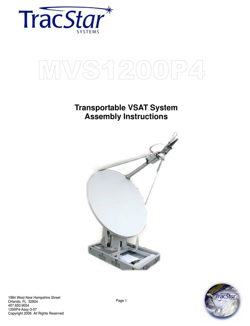
Mobile VSAT Antenna System
Assembly Instructions
These commodities, technologies, and/or software were exported from the
United States in accordance with U.S. Export Administration Regulations.
Diversion contrary to U.S. Law is prohibited.
1984 West New Hampshire Street
Orlando, FL 32804
407.650.9054
750P5-Assy-2-07
Copyright 2006 All Rights Reserved
1200P2F&D-Assy-1-06 Page 2
Copyright 2006 All Rights Reserved
Step 1
Open latches and remove protective cases
from the pedestal.
Step 2
Set the case covers aside.
Note the accessories inside the two lids.
1200P2F&D-Assy-1-06 Page 3
Copyright 2006 All Rights Reserved
Step 3
Open latches and remove the cover from
the reflector case.
Step 4
Set the case cover aside.
Step 5
Note the orientation of the reflector panels.
1200P2F&D-Assy-1-06 Page 4
Copyright 2006 All Rights Reserved
Step 6
Open latches and secure the two
reflector pieces together. Secure
the reflector latches.
Carefully set the reflector aside.
1200P2F&D-Assy-1-06 Page 5
Copyright 2006 All Rights Reserved
Step 7
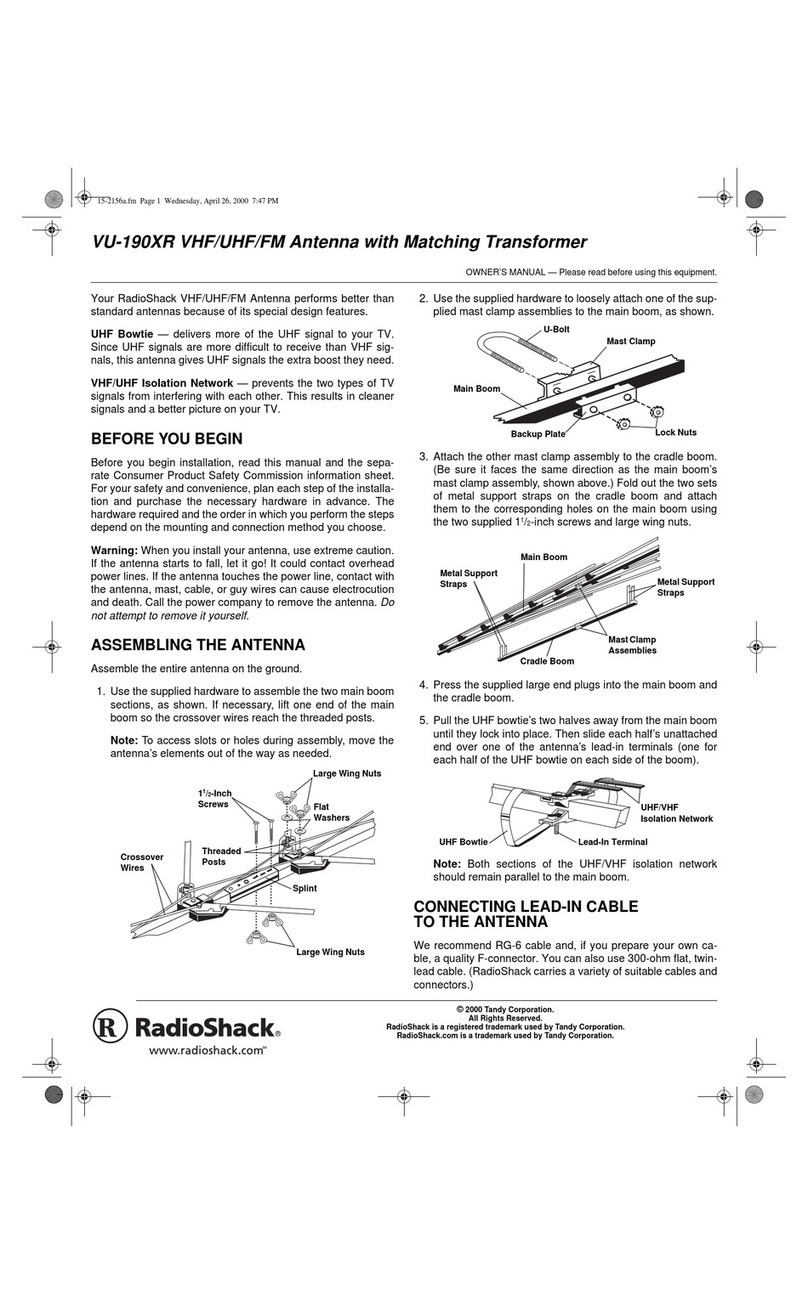
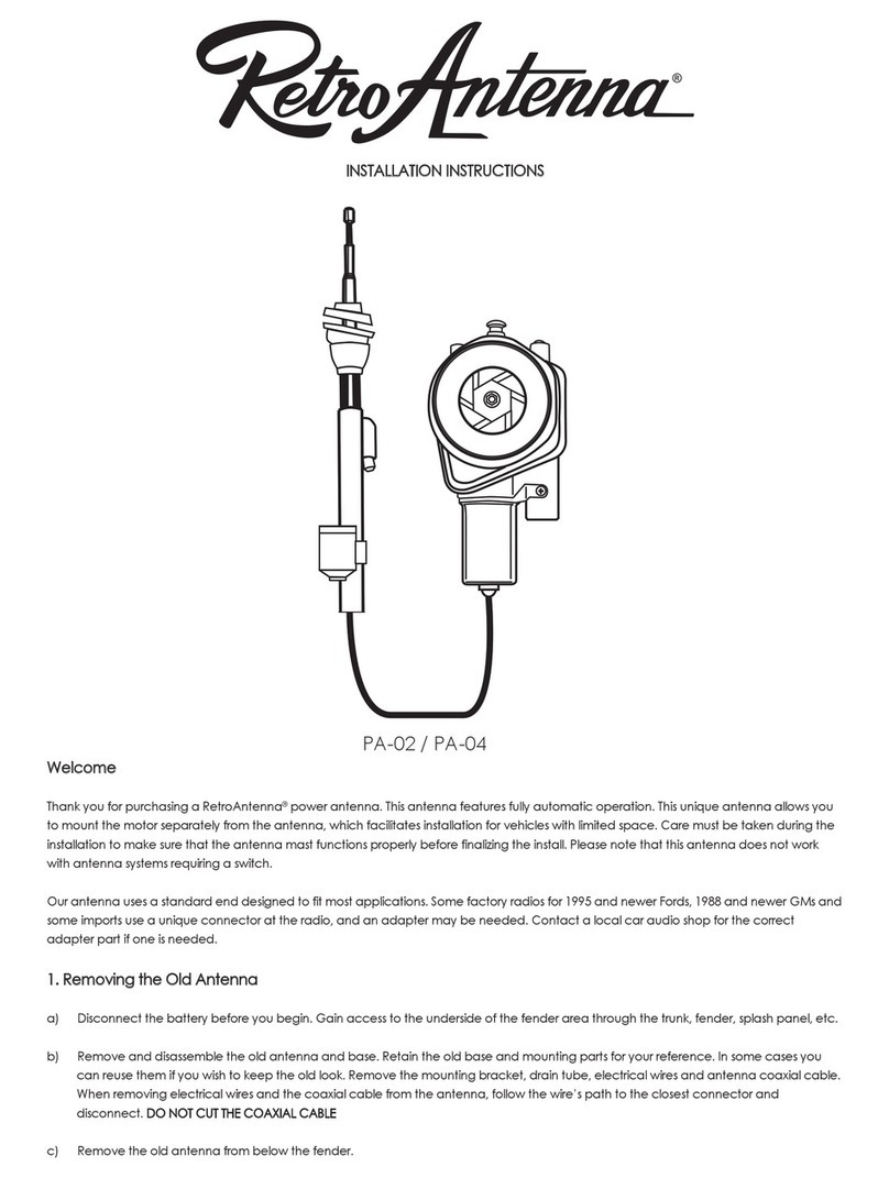
Connect the antenna controller
cable to the antenna.
Step 8
Connect the other end of the an-
tenna controller cable to the
“Antenna” connector in the back
of the equipment rack.
Step 9
Connect the Tx Port (RED) of
the antenna to the Tx Port in the
back of the equipment rack.
Step10
Connect the Rx Port (BLUE) of
the antenna to the Rx Port in the
back of the equipment rack.
Step11
Apply AC Power to the equip-
ment rack.
1200P2F&D-Assy-1-06 Page 6
Copyright 2006 All Rights Reserved
Step 12
From the READY screen on the
controller display, press the “ + “
button for 2 seconds. The pedes-
tal will begin to lift.
Alternately, press the DEPLOY
button on the back of the antenna.
Step 13
The pedestal will stop at the posi-
tion to mount the reflector.
1200P2F&D-Assy-1-06 Page 7
Copyright 2006 All Rights Reserved
EXTEND THE BOOM
Step 14
Locate the knobs on the inside of the
boom arm. Remove BOTH knobs.
1200P2F&D-Assy-1-06 Page 8
Copyright 2006 All Rights Reserved
EXTEND THE BOOM
Step 15
After removing the two knobs in Step 7,
pull the boom fully forward.
Step 16
Reattach the knobs to the boom in the
new position. The knobs will screw into
the holes closest to the rear end of the
boom.
1200P2F&D-Assy-1-06 Page 9
Copyright 2006 All Rights Reserved
MOUNT THE REFLECTOR
Step 17
Carefully place the reflector on the ped-
estal base. Secure the four mounting
screws on the back and the one at the
bottom of the reflector.
1200P2F&D-Assy-1-06 Page 10
Copyright 2006 All Rights Reserved
Step 18
Remove the boom support struts from their
position on each side of the pedestal base.
Step 19
Lifting the end of the feed boom, secure the
struts to the reflector and to the feed boom
ball studs on both sides of the reflector.
1200P2F&D-Assy-1-06 Page 11
Copyright 2006 All Rights Reserved
Step 20
Press the “ + ” button again and the
antenna will resume deployment.
Alternately, press the DEPLOY button on the
back of the antenna.
Step 21
The antenna will align to the desired data sat-
ellite.
.
1200P2F&D-Assy-1-06 Page 12
Copyright 2006 All Rights Reserved
Step 22
STOWING
Press the “ - ” button and the antenna
will begin stowing.
Alternately, press the STOW button
on the back of the antenna.
Step 23
The antenna will stop at a position
where it is safe to remove the reflec-
tor.
1200P2F&D-Assy-1-06 Page 13
Copyright 2006 All Rights Reserved
.
Step 24
Lifting the end of the feed boom, remove
the struts from the reflector and the feed
boom ball studs on both sides of the reflec-
tor.
Carefully set the boom down on the pedes-
tal.
Step 25
Replace the boom support struts in their
position on each side of the pedestal base.
1200P2F&D-Assy-1-06 Page 14
Copyright 2006 All Rights Reserved
Step 26
Loosen the captive screws holding the
back and the bottom of the reflector to the
antenna pedestal.
Remove the reflector.
Step 27
Loosen the captive locks holding the
two pieces of the reflector together.
Step 28
Separate the two reflector halves.
1200P2F&D-Assy-1-06 Page 15
Copyright 2006 All Rights Reserved
Step 29
Re-insert the reflector halves into the
equipment case, keeping the sections
separated with the insulation material built
into the case.
Step 30
Re-secure the lid to the reflector case.
1200P2F&D-Assy-1-06 Page 16
Copyright 2006 All Rights Reserved
COMPRESS THE BOOM
Step 31
Remove the two knobs securing the
boom arm to the pedestal.
Step 32
Push the boom feed back into the STOW
position. DO NOT PUSH ON THE LNB
ASSEMBLY.
Step 33
Reattach the knobs to the boom in the
STOW position. The knobs will screw
into the holes farthest from the rear end
of the boom.
1200P2F&D-Assy-1-06 Page 17
Copyright 2006 All Rights Reserved
Step 34
From the REMOVE DISH screen
on the controller display, press the
ENTER button. The pedestal will
resume stowing.
Step 35
The pedestal will stop at the full
stow position.
Step 36
Remove AC Power from the unit.
Disconnect all cables from the
case.
1200P2F&D-Assy-1-06 Page 18
Copyright 2006 All Rights Reserved
Step 37
Remove all cables from the antenna ped-
estal.
Step 38
Re-install the cover over both antenna
sides.
1200P2F&D-Assy-1-06 Page 19
Copyright 2006 All Rights Reserved
Step 39
Re-secure all latches holding the cover to
the pedestal.
Step 40
.
Check all latches on the reflector case.
1200P2F&D-Assy-1-06 Page 20
Copyright 2006 All Rights Reserved
NOTES:

Other manuals for MVS1200P2 F&D

2

Other TracStar Antenna manuals

TracStar SV-360 Manual

TracStar

TracStar SV-360 Manual

TracStar MVS1200P4 User manual

TracStar

TracStar MVS1200P4 User manual

TracStar MVS1200P2 F&D User manual

TracStar

TracStar MVS1200P2 F&D User manual

TracStar MVS1200P2 F&D User manual

TracStar

TracStar MVS1200P2 F&D User manual

Popular Antenna manuals by other brands

Poynting Moray Series user guide

Poynting

Poynting Moray Series user guide

FibroLAN Falcon Installation guidelines

FibroLAN

FibroLAN Falcon Installation guidelines

THOMSON ANT1439 operating instructions

THOMSON

THOMSON ANT1439 operating instructions

Vivanco TVA 100 operating instructions

Vivanco

Vivanco TVA 100 operating instructions

Intellinet 521413 installation guide

Intellinet

Intellinet 521413 installation guide

Intellian i4 Inland Installation and operation user guide

Intellian

Intellian i4 Inland Installation and operation user guide

Directive Systems & Engineering DSE9112LY manual

Directive Systems & Engineering

Directive Systems & Engineering DSE9112LY manual

Buffalo WLE-AT-NDBHB Technical specifications

Buffalo

Buffalo WLE-AT-NDBHB Technical specifications

DX Engineering DXE-SMBA-2 manual

DX Engineering

DX Engineering DXE-SMBA-2 manual

Sinclair SC466-HF LDF Series installation instructions

Sinclair

Sinclair SC466-HF LDF Series installation instructions

Cisco AIR-ANT2485P-R quick start guide

Cisco

Cisco AIR-ANT2485P-R quick start guide

Poynting PUCK-V1-W user guide

Poynting

Poynting PUCK-V1-W user guide

Terrestrial Digital XG91 Assembly and installation

Terrestrial Digital

Terrestrial Digital XG91 Assembly and installation

Teleco Motosat65 Installation guide and user's manual

Teleco

Teleco Motosat65 Installation guide and user's manual

Emerson 781S quick start guide

Emerson

Emerson 781S quick start guide

Whoop Wireless HE4 user manual

Whoop Wireless

Whoop Wireless HE4 user manual

Aardvark VANSAT Raven Installation and operation manual

Aardvark

Aardvark VANSAT Raven Installation and operation manual

One Forall SV9450 Quick installation guide

One Forall

One Forall SV9450 Quick installation guide

manuals.online logo
manuals.online logoBrands
  • About & Mission
  • Contact us
  • Privacy Policy
  • Terms and Conditions

Copyright 2025 Manuals.Online. All Rights Reserved.