Trademaster BM-20 Plus User manual
BEFORE USE, ENSURE EVERYONE USING THIS MACHINE READS AND UNDERSTANDS
ALL SAFETY AND OPERATING INSTRUCTIONS IN THIS MANUAL .
Serial #............................................ Date of Purchase............................
Ver: 1.0 01/05/2015
OPERATOR’S MANUAL
PART# WA-B20+
BM-20 PLUS
BEVELLING MACHINE

BM-20 PLUS Operator’s Manual2
IMPORTED & DISTRIBUTED BY
INDUSTRIAL TOOL & MACHINERY SALES
18 BUSINESS ST
YATALA QLD 4207 AUSTRALIA
T
F
E
W
07 3287 1114
07 3287 1115
www.industrialtool.com.au
WARRANTY TERMS
In addition to any warranties or conditions implied by applicable Statute or Regulations, Industrial Tool
& Machinery Sales warrants all of it’s products against defective workmanship and faulty materials for
a period of twelve (12) months from the date of purchase, unless otherwise stated. At our option we will
repair or replace, free of charge, any item on the condition that:
• The complete machine or tool is returned, freight prepaid to ITM or one of it’s authorised service
agents as directed by ITM, and is found to have a material or constructional defect.
• The machine or tool has not been subject to misuse, neglect or damage by accident.
• The fault is not a result of normal “wear and tear”.
• Written permission has been received from ITM prior to commencement of repair.
• Repairs, tampering or modification carried out by unauthorised personnel will void all warranty.
• Consumable items such as cutting tools, pilot pins, saw blades, grinding wheels etc. are NOT
covered by warranty.
Our goods come with guarantees which cannot be excluded under the Australian Consumer Law.
You are entitled to replacement or refund for a major failure and to compensation for other reasonably
foreseeable loss or damage. You are also entitled to have the goods repaired or replaced if the goods
fail to be of acceptable quality and the failure does not amount to a major failure.
CONTENTS
1. GENERAL INFORMATION 3
1.1. Application 3
1.2. Technical data 3
1.3. Design 5
1.4. Equioment included 5
2. SAFETY PRECAUTIONS 6
3. STARTUP AND OPERATION 8
3.1. Adjusting the bevel angle and width 8
3.2. Operating 9
3.3. Replacing the cutting inserts 11
3.4. Replacing the milling cutters 12
4. ACCESSORIES 13
4.1. 0° guide set for facing plates 13
4.2. Guides for bevelling pipes 14
5. WIRING DIAGRAM 16
6. SPARE AND WEARING PARTS 17
7. PARTS BREAKDOWN 18
BM-20 PLUS Operator’s Manual 3
1. GENERAL INFORMATION
1.1. Application
The BM-20 is a bevelling machine designed to mill plates made of carbon steel at the
angle of 15–60° and with the bevel width up to 21 mm (13/16’’).
Using accessories will allow facing plates as well as bevelling pipes with outer
diameters of 150–300 mm (6–12’’) or 300–600 mm (12–24’’).
1.2. Technical data
Voltage 1~ 220–240 V, 50–60 Hz
1~ 110–120 V, 50–60 Hz
Power 1600 W (for 50 Hz)
1800 W (for 60 Hz)
Rotational speed 2780–3340 rpm (at 230 V)
2740–3290 rpm (at 115 V)
Protection level IP 20
Protection class I
Milling speed 550 m/min (1800 ft/min, for 50 Hz)
650 m/min (2200 ft/min, for 60 Hz)
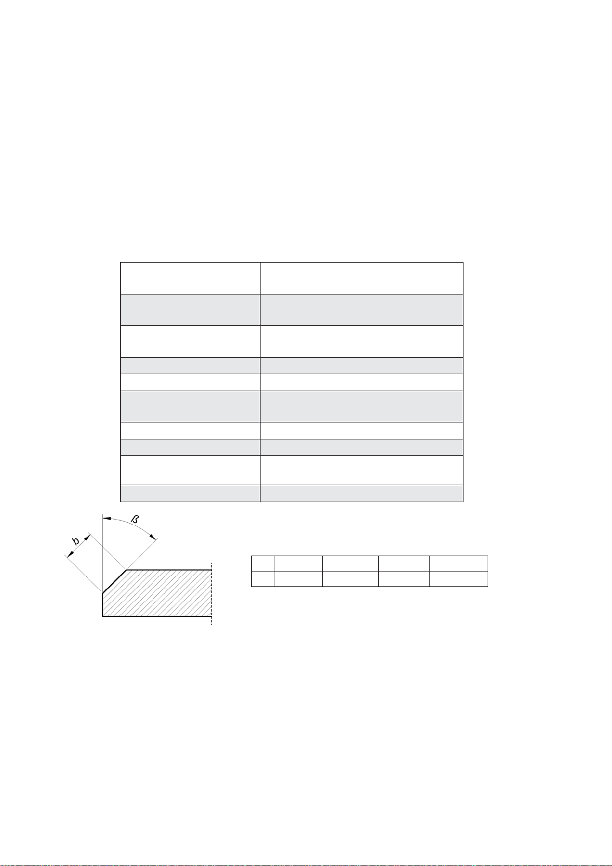
Maximum bevel width (b) 21 mm (13/16’’, Fig. 1)
Bevel angle (ß) 15–60° (Fig. 1)
Vibration level Machine harmful for health. Take
periodic breaks during operation.
Weight 20.5 kg (45 lbs)
Fig. 1. Bevel dimensions; maximum bevel width depending on the angle
ȕ15° 30° 45° 60°
b 21 mm 20.5 mm 21 mm 20.5 mm

BM-20 PLUS Operator’s Manual4
446 mm (17.6’’)
315 mm (12.4’’)
323 mm (12.7’’)
BM-20 PLUS Operator’s Manual 5
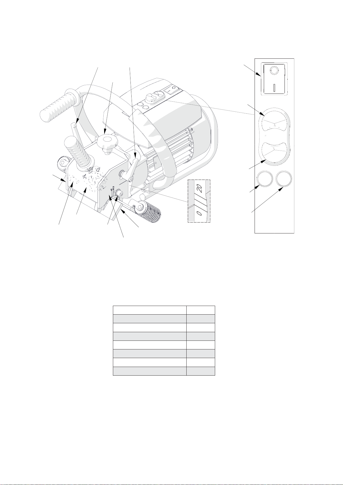
1.3. Design
Fig. 2. View of the machine and control panel
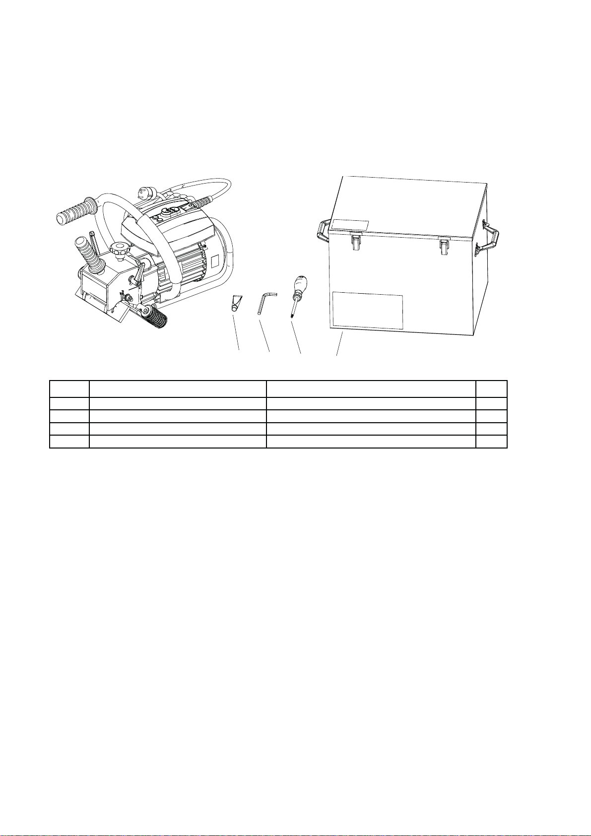
1.4. Equipment included
The BM-20 plus is supplied in a metal box with complete standard equipment. The
included equipment consists of:
Bevelling machine 1 unit
Cutting insert 10 units
Metal box 1 unit
Tool container 1 unit
6 mm hex wrench 1 unit
T15P torx screwdriver 1 unit
Grease for screws 1 unit
Operator’s Manual 1 unit
Guide set
Depth knob
Bevel width pitch
Bevel angle pitch
Bevel angle lock screws
Depth lock levers Power switch
START
STOP
Motor lamp
Overload lamp
Milling cutters
Milling
cutters
cover

BM-20 PLUS Operator’s Manual6
2. SAFETY PRECAUTIONS
1. Before beginning, read this Operator’s Manual and complete proper occupational
safety and health training.
2. The machine must be used only in applications specified in this Operator’s Manual.
3. The machine must be complete and all parts must be genuine and fully operational.
4. Theelectricalsupplyspecificationsmustconform tothosespecifiedontheratingplate.
5. The machine must be plugged into a properly grounded (earthed) socket-outlet.
6. Never pull the power cord as this may damage it and result in electric shock.
7. Untrained bystanders must not be present near the machine.
8. Before beginning, check the condition of the machine and electrical supply, including
power cord, plug, control panel components, and milling tools.
9. Keep the machine dry. Exposure to rain, snow, or frost is prohibited.
10. Keep the work area well lit, clean, and free of obstacles.
11. Never use machine near flammable liquids or gases, or in explosive environments.
12. Use only tools specified in this Operator’s Manual.
13. Never use dull or damaged tools.
14. Mount the cutting inserts and the milling cutters securely. Remove adjusting keys
and wrenches from the work area before connecting the plug to the power outlet.
15. If the cutting edge of an insert is worn, rotate the insert in the socket by 90° or, if
all edges are worn, replace with a new insert specified in this Operator’s Manual.
16. Before every use, inspect the machine to ensure it is not damaged. Check whether
any part is cracked or improperly fitted. Make sure to maintain proper conditions
that may affect the operation of the machine.
17. Always use eye and hearing protection, non-skid footwear, gloves, and protective
clothing during operation. Do not wear loose clothing.
18. Do not touch moving parts or metal chips formed during milling. Prevent objects
from being caught in moving parts.
19. After every use, remove metal chips from the machine, especially from the milling
cutters. Never remove metal chips with bare hands. Clean the machine with a
cotton cloth without using any agents.
20. Cover steel parts with a thin anti-corrosion coating to protect the machine from
rust when not in use for any extended period.

BM-20 PLUS Operator’s Manual 7
21. Maintain the machine and mount/dismount parts and tools only with the power
cord unplugged from the power outlet.
22. Repair only in a service center appointed by the seller.
23. If the machine falls from any height, is wet, or has other damage that could affect
the technical state of the machine, stop the operation and immediately send the
machine to the service center for inspection and repair.

BM-20 PLUS Operator’s Manual8
3. STARTUP AND OPERATION
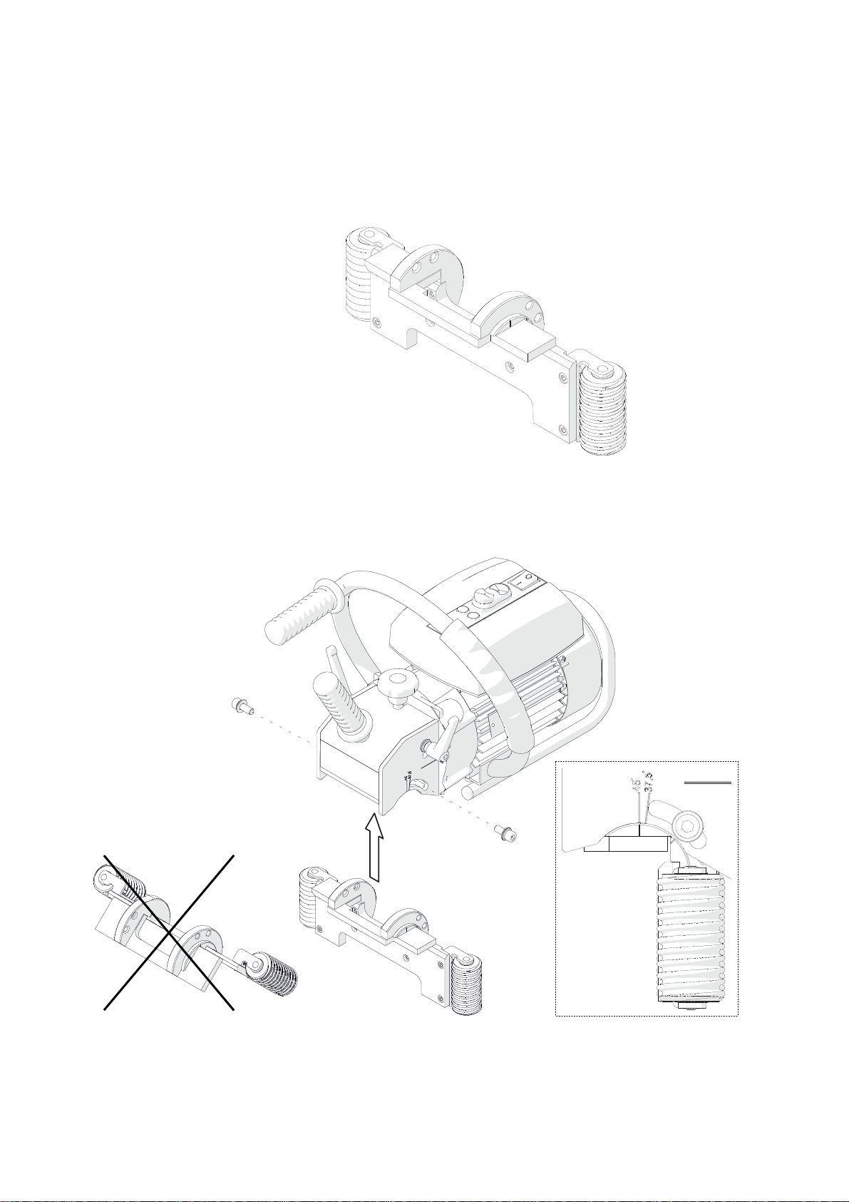
3.1. Adjusting the bevel angle and width
Unplug the power cord from the power outlet. Begin with setting the bevel width to
zero. To do this, loosen two depth lock levers (Fig. 3) and rotate the depth knob to set
the indication ‘0’ on the bevel width pitch.
Fig. 3. Initial setting the bevel width to zero
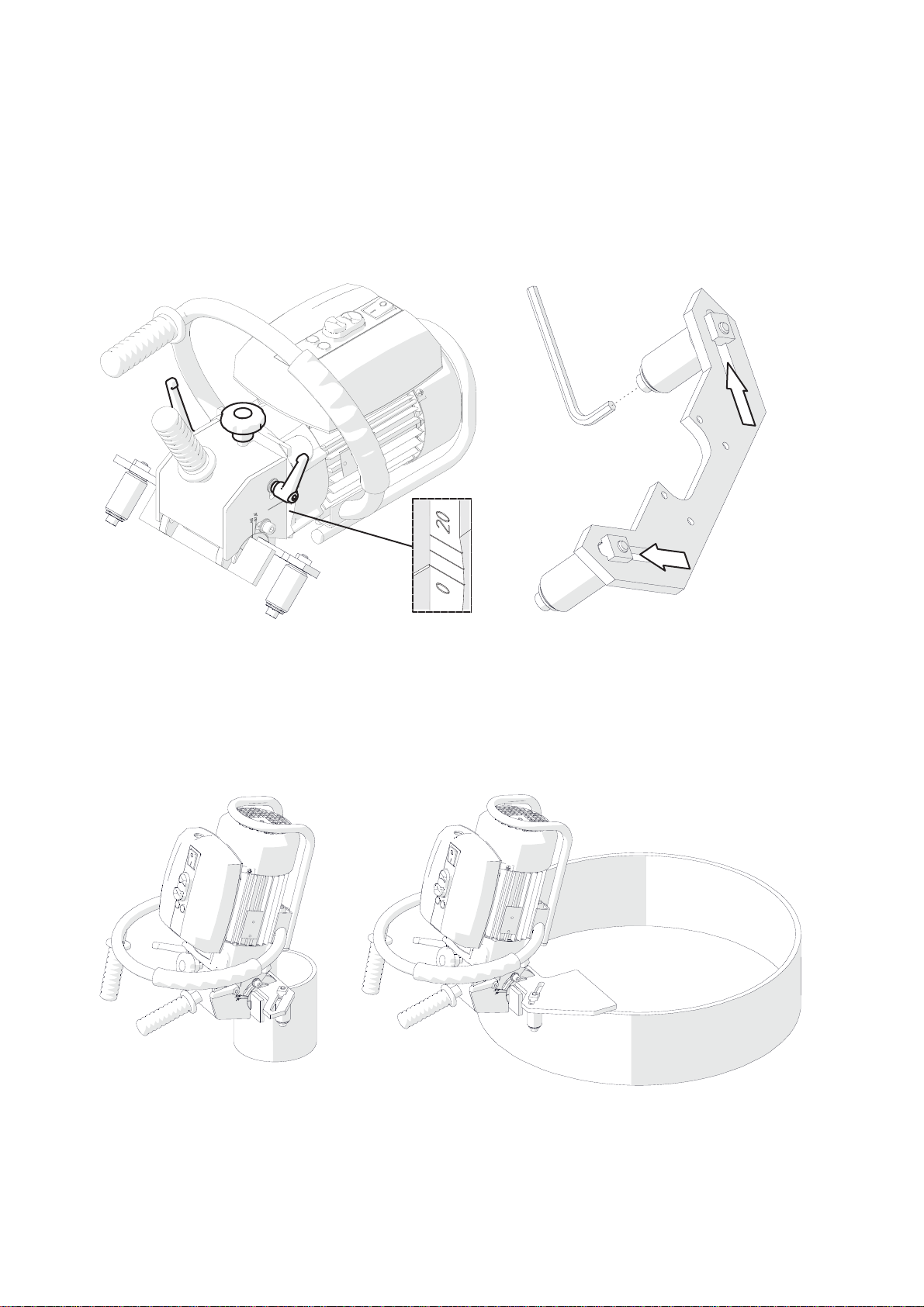
Then, to set the required bevel angle (Fig. 4), use the 6 mm hex wrench to loosen
two side screws, rotate the guide set to set the angle on the pitch, and tighten the
screws in this new position.
Fig. 4. Setting the bevel angle (45° is set on the drawing)
All safety precautions must be closely observed

BM-20 PLUS Operator’s Manual 9
After setting the bevel angle, adjust the bevel width using the depth knob. The
width pitch provides only a rough value as the bevel width varies with the angle.
The maximum bevel width (b= 21 mm, 13/16’’) is obtained for 45°. The demanded
bevel width for the required angle must be determined experimentally by gradually
increasing the penetration of the milling cutters into the workpiece.
3.2. Operating
After setting the bevel angle and width, connect the machine to a properly grounded
power outlet. Then, place the machine vertically on the right side of the workpiece in
such a way to rest the rollers on the plate (Fig. 5) and maintain a gap between the
milling cutters and the plate. Next, power on the machine by toggling the power switch
to position ‘I’ and start the motor using the green START button. Slide the machine
towards the plate face and bevel by sliding the machine to the left, constantly pressing
the machine against the workpiece.
Bevelling is performed according to the counter-rotation. The rotation direction of
the milling cutters is marked on the motor disk under the milling cutters cover.
Fig. 5. Machine properly positioned on the workpiece
The feed rate will depend on the profile and composition of the workpiece.
Most steels capable of being welded can be bevelled in one pass. However,
bevels wider than 12 mm (1/2’’) should be accomplished in at least two or three passes
as this will require less effort and the process will take less total time than for bevelling
in a single pass.
Feed direction
Power switch
START
Slide towards after starting the motor

BM-20 PLUS Operator’s Manual10
To obtain the maximum bevel width (21 mm, 13/16’’) in two passes, the bevel after
the first pass should be about 14 mm (9/16’’) wide, while for three passes about 12 mm
(1/2’’) wide after the first pass and about 16 mm (5/8’’) wide after the second one.
If the maximum permitted motor load is exceeded, resulting from, for instance,
too fast feed, the red overload lamp will light. Continuing the operation in such a case
will trigger the safety circuit and shut down the motor. If as a result of an overload the
motor will shut down, separate the machine from the working edge, turn off the power
by setting the power switch in position ‘O’, and after the red overload lamp turns off,
power on the machine again.
Operating near the overload condition (with the red lamp flashing) is allowed,
however, never allow the motor temperature to exceed 85°C (185°F) as this can lead
to damage of the motor windings. After every one hour of operating under full load,
stop the motor for 10–15 minutes. Never cool the motor by running it without load as
it will become heated even faster than when working with load.
Once the work is finished, stop the motor using the STOP button and toggle the
power switch to the position ‘O’.
Clean the machine with a cotton cloth without using any agents.

BM-20 PLUS Operator’s Manual 11
3.3. Replacing the cutting inserts
Unplug the power cord from the power outlet, then unscrew the levers (Fig. 6) and
remove the milling cutters cover.
Fig. 6. Removing the milling cutters cover
Use the supplied T15P screwdriver to unscrew the set screw (Fig. 7), then remove
the insert and clean the socket. Next, place the 90° rotated insert again or replace
with a new one if all four edges of the insert are worn.
Fig. 7. Replacing the cutting inserts
Set screw
BM-20 PLUS Operator’s Manual12
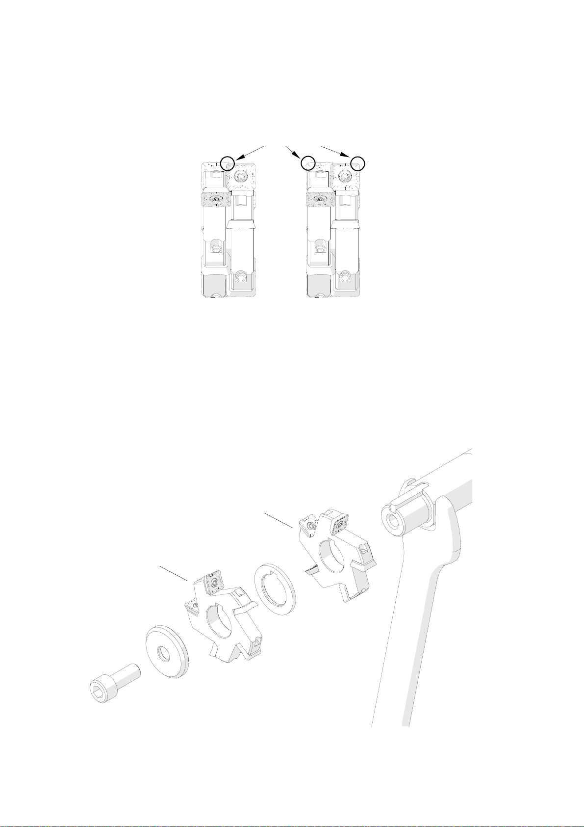
When establishing bevels with low width, the cutting inserts wear only on one,
internal corner. Then, the good action is to change the inserts between the milling
cutters (Fig. 8), which will extend the life of the inserts.
Fig. 8. Changing the cutting inserts between milling cutters
3.4. Replacing the milling cutters
Remove the milling cutters cover as shown in Fig. 6. Next, use the 26 mm flat wrench
to lock the rotation of the spindle, then use the 8 mm hex wrench to unscrew the
mounting screw and remove the milling cutters as shown in Fig. 9. Assemble in
reverse order. The 26 mm flat wrench is not included in standard equipment.
Fig. 9. Replacing the milling cutters
Worn corners
Milling cutter no. 2
Milling cutter no. 1
BM-20 PLUS Operator’s Manual 13
4. ACCESSORIES
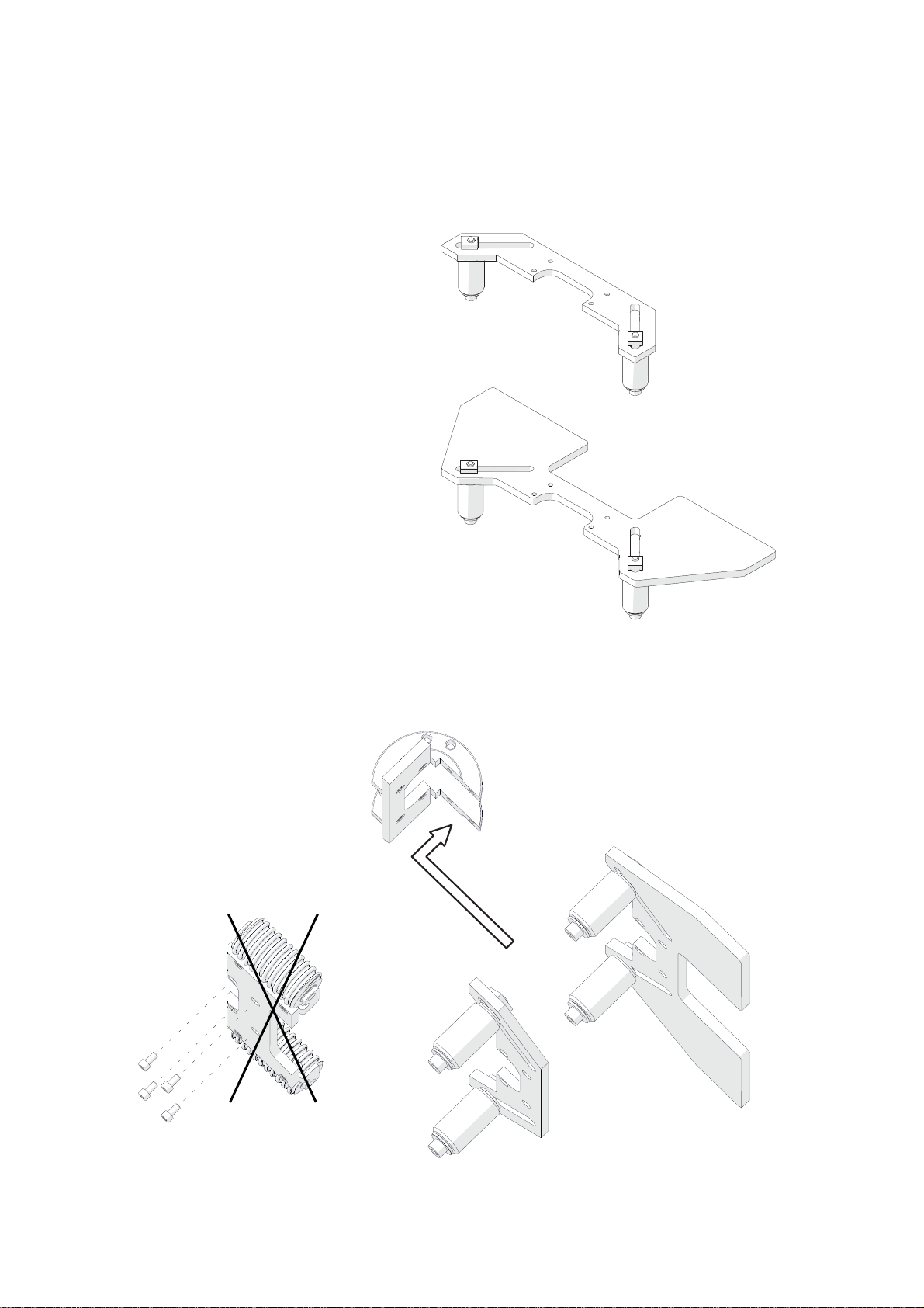
4.1. 0° guide set for facing plates
Allows facing plates.
To mount the set, use the 6 mm hex wrench to unscrew two side screws (Fig. 10)
and remove the standard guide set. Then, mount the 0° guide set in such a way to
obtain the indication of 45° on the right pitch, and secure with the same screws.
Fig. 10. Dismounting the standard guide set and mounting the 0° guide set
Part number:
ZSP-0075-32-00-00-1
BM-20 PLUS Operator’s Manual14
4.2. Guides for bevelling pipes
Allow bevelling pipes with outer diameters of 150–300 mm (6–12’’) or 300–600 mm
(12–24’’).
To adapt the machine for work on pipes, first dismount the standard guide set as
shown in Fig. 10. Then, use the 4 mm hex wrench to unscrew four screws from the
dismounted guide set and assemble the guide set for pipes as indicated (Fig. 11).
Fig. 11. Assembling the guide set for pipes
Part number:
ZSP-0075-31-00-00-0
(for pipes with diameters of 150–300 mm)
Pat number:
ZSP-0075-31-00-00-1
(for pipes with diameters of 300–600 mm)
BM-20 PLUS Operator’s Manual 15
Mount the assembled guide set to the machine, securing with the side screws as
shown in Fig. 10.
Loosen the depth lock levers (Fig. 12) and rotate the depth knob to set the
indication ‘0’ on the bevel width pitch. Then, use the 6 mm hex wrench to loosen
the rollers and separate the rollers from each other as far as possible.
Fig. 12. Setting the depth and the rollers position before placing the machine on the pipe
Place the machine on a vertically positioned pipe in such a way to bring the
surfaces of the guide set in close contact with the face and side surface of the pipe.
Then, move the rollers symmetrically to adjoin them to the pipe (Fig. 13) and tighten
in this position. Set the required bevel angle and width as described before.
Fig. 13. Machine prepared for work on pipes with diameters of 150–300 mm and 300–600 mm
BM-20 PLUS Operator’s Manual16
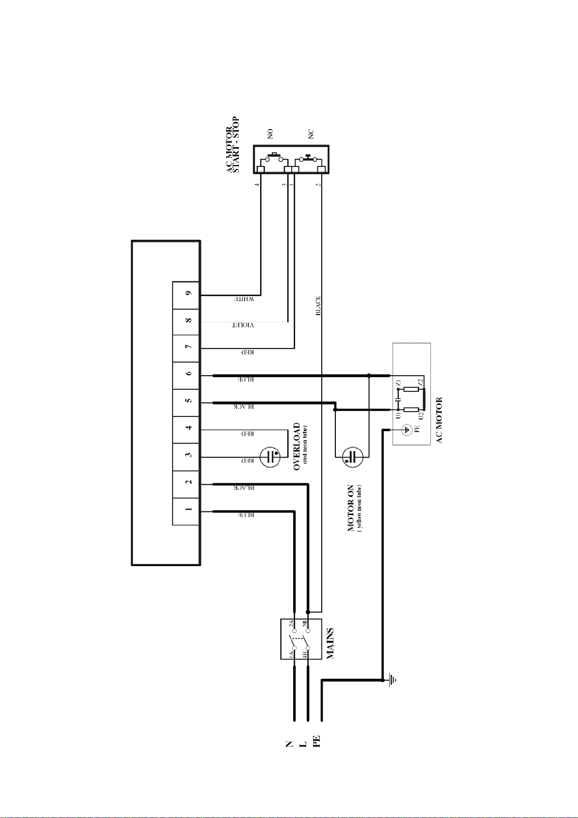
5. WIRING DIAGRAM

BM-20 PLUS Operator’s Manual 17
6. SPARE AND WEARING PARTS
Name Number
Milling cutter no. 1 (5 cutting inserts required) KRP-0539-02-00-00-0
Milling cutter no. 2 (5 cutting inserts required) KRP-0539-03-00-00-0
Cutting insert (sold 10 per box) PLY-000282
Mounting screw for inserts SRB-000311
T15P torx screwdriver for mounting screws WKT-000005
Grease for screws (5 g, 0.17 oz) SMR-000005
BM-20 PLUS Operator’s Manual18
!"
!"#$%&
# '(")#(
*+!#
7. PARTS BREAKDOWN

BM-20 PLUS Operator’s Manual 19
9
9
9
'
'
9
'
9
'
'
9

BM-20 PLUS Operator’s Manual20
:# #;%)*()$
$' !#!$&
$' !#!$&
$' !#!$&<:=
' )!
) !!&
) !!&
% %)*#:
9 ! % %)*#:#!&
$' (
> *:%$'?
>9 #!)! !";&
>9 #!)! !";&
) ("):'
$' ") !!( !#(
;9 #:%)*%)
) %) %+):
' $ !:)$(9
$' %)*(' 9
9 $ %)*(9
@' ()$ &9
' ("!#($##'A'
' ("!#($##A
("!#($##9A
!:)%)*#
9 #!#$)($#A
("!#:!)($#'A
' $ # * )$%(%) %+*
*:%$%
9 > *:%$%%%(!
! *:%$!:)%)*%
! *:%$!:)%)*%%
("!#($##A 9
*:%$%%
!
)' ):
$ !:)$(
' $ %)*(
9 ("!#($##A
9 $ ' #!)%#!$: ;&
9 $ ' #!)%#!$: ;&
' #!)! (!:%)*#!&
!)' $
!)' ; !
;9 !!
9 #
) ):(!
$' ") !!( !#(
' $' ") !!( !#(9
9 #!#$)($#A
9 )$ ##%!+&
9 )$ ##%!9+B&
Table of contents
Other Trademaster Power Tools manuals


