Trademaster BM16 User manual
BEFORE USE, ENSURE EVERYONE USING THIS MACHINE READS AND UNDERSTANDS
ALL SAFETY AND OPERATING INSTRUCTIONS IN THIS MANUAL .
Serial #............................................ Date of Purchase............................
OPERATOR’S MANUAL
BM16
BEVELLING MACHINE
INDUSTRIAL TOOLS
ul. Elewatorska 23/1, 15-620 Białystok, Poland
Phone: +48 85 678-34-00, Fax: +48 85 651-15-31
www.promotech.eu e-mail: office@promotech.eu
OPERATOR’S MANUAL
B
BM
M-
-
1
16
6
BEVELLING MACHINE

2
TRADEMASTER BM16 BEVELLING MACHINE
TABLE OF CONTENTS
LIMITED WARRANTY
Industrial Tool & Machinery Sales (hereinafter referred to as ITMS) will, within twelve (12)
months from the original date of purchase, repair or replace any goods found to be defective
in materials or workmanship.
This warranty is void if the item has been damaged by accident, neglect, improper service or
other causes not arising out of defects in materials or workmanship. This warranty does not
apply to machines and/or components which have been altered, changed, or modified in any
way, or subjected to overloading or use beyond recommended capacities and specifications.
Worn componentry due to normal wear and tear is not a warranty claim. Goods returned
defective shall be returned prepaid freight to ITMS or agreed repair agent, which shall be the
buyer’s sole and exclusive remedy for defective goods. ITMS accepts no additional liability
pursuant to this guarantee for the costs of travelling or transportation of the product or parts to
and from ITMS or the service agent or dealer, such costs are not included in this warranty.
Our goods come with guarantees which cannot be excluded under the Australian Consumer
Law. You are entitled to replacement or refund for a major failure and to compensation
for other reasonably foreseeable loss or damage. You are also entitled to have the goods
repaired or replaced if the goods fail to be of acceptable quality and the failure does not
amount to a major failure.
THE MANUFACTURER RESERVES THE RIGHT TO MAKE IMPROVEMENTS AND
MODIFICATIONS TO DESIGN WITHOUT PRIOR NOTICE.
PRODUCTS IMPORTED AND DISTRIBUTED NATIONALLY BY:
INDUSTRIAL TOOL & MACHINERY SALES
18 BUSINESS ST, YATALA QLD 4207
F: 07 3287 1115 W: www.industrialtool.com.au
1.GENERAL INFORMATION............................................................................................3
1.1.Application...................................................................................................................3
1.2.Technical data.............................................................................................................3
1.3.Equipment included.....................................................................................................4
1.4.Dimensions..................................................................................................................4
1.5.Design .........................................................................................................................5
2.SAFETY PRECAUTIONS...............................................................................................6
3.STARTUP AND OPERATION........................................................................................8
3.1.Installing and removing the milling head .....................................................................8
3.2.Adjusting the bevel parameters.................................................................................10
3.3.Adjusting the guide for bevelling with radius .............................................................11
3.4.Preparing...................................................................................................................11
3.5.Operating...................................................................................................................12
3.6.Replacing the cutting inserts .....................................................................................13
3.7.Replacing the roller....................................................................................................14
3.8.Replacing the brushes...............................................................................................15
4.ACCESSORIES............................................................................................................16
4.1.Guide for bevelling pipes...........................................................................................16
4.2.Anti-scratch guide sticker ..........................................................................................18
4.3.Worktable fixture........................................................................................................18
4.4.Radius insert positioner.............................................................................................22
4.5.Milling tools................................................................................................................23
5.SPARE AND WEARING PARTS..................................................................................23
6.WIRING DIAGRAM ......................................................................................................24
7.PARTS LIST.................................................................................................................25

3
GENERAL INFORMATION
BM-16
This document is protected by copyrights.
Copying, using, or distributing without permission of PROMOTECH is prohibited.
3
1. GENERAL INFORMATION
1.1. Application
The BM-16 is a bevelling machine designed to mill edges of plates and pipes made
of steel, aluminum alloys, brass,or plastics.
Depending on the milling head used the machine allows bevelling workpieces
with a thickness of at least 1.5 mm (0.06’’) at the angle of 22.5°, 30°, 37.5°, 45°, 50°,
55°, 60°, or 65° to the maximum bevel width of 16 mm (0.63’’). A radius milling head
allows bevelling with a radius of 2, 3, 4, or 5 mm. The minimum diameter of a hole to
be machined is 40 mm (1.57’’).
An optional guide allows bevelling pipes, sticker protects aluminum workpieces
against scratches, and worktable fixture allows bevelling flat bars.
1.2. Technical data
Voltage
1~ 220–240 V, 50–60 Hz
1~ 110–120 V, 50–60 Hz
Power
2200 W
Rotational speed (without load)
1800–5850 rpm
Protection level
IP 20
Protection class
II
Maximum bevel width (b)
16 mm (0.63’’, Fig. 1)
Bevel angle (ß, depends on the
milling head used)
22.5°, 30°, 37.5°, 45°, 50°, 55°, 60°, 65°
(Fig. 1)
Minimum workpiece thickness for bevelling
1.5 mm (0.06’’)
Minimum hole diameter
40 mm (1.57’’)
Edge radius
2 mm, 3 mm, 4 mm, 5 mm (Fig. 1)
Noise level
More than 70 dB
Vibration level
2.3 m/s
2
(7.5 ft/s
2
)
Machine harmful for health. Take periodic
breaks during work.
Required ambient temperature
0–40°C (34–104°F)
Weight (without milling head)
10 kg (22 lbs)
Fig. 1. Bevel dimensions
4
GENERAL INFORMATION
BM-16
This document is protected by copyrights.
Copying, using, or distributing without permission of PROMOTECH is prohibited.
4
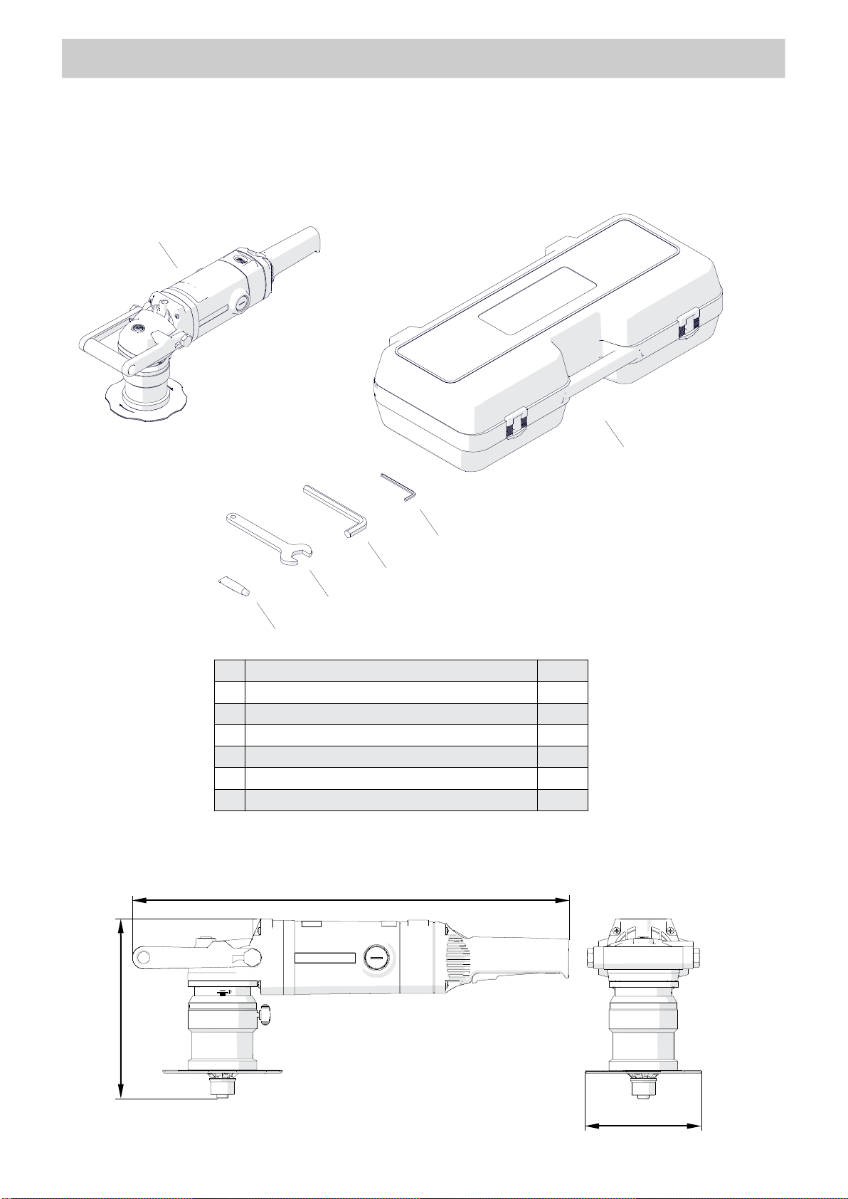
1.3. Equipment included
1
Bevelling machine (without milling head)
1 unit
2
Plastic box
1 unit
3
5 mm hex wrench
1 unit
4
14 mm hex wrench
1 unit
5
32 mm flat wrench
1 unit
6
Grease for screws (5 g, 0.17 oz)
1 unit
–
Operator’s Manual
1 unit
1.4. Dimensions
1
3
4
5
2
6
585 mm (23’’)
241 mm (9.4’’)
156 mm (6.1’’)
5
GENERAL INFORMATION
BM-16
This document is protected by copyrights.
Copying, using, or distributing without permission of PROMOTECH is prohibited.
5
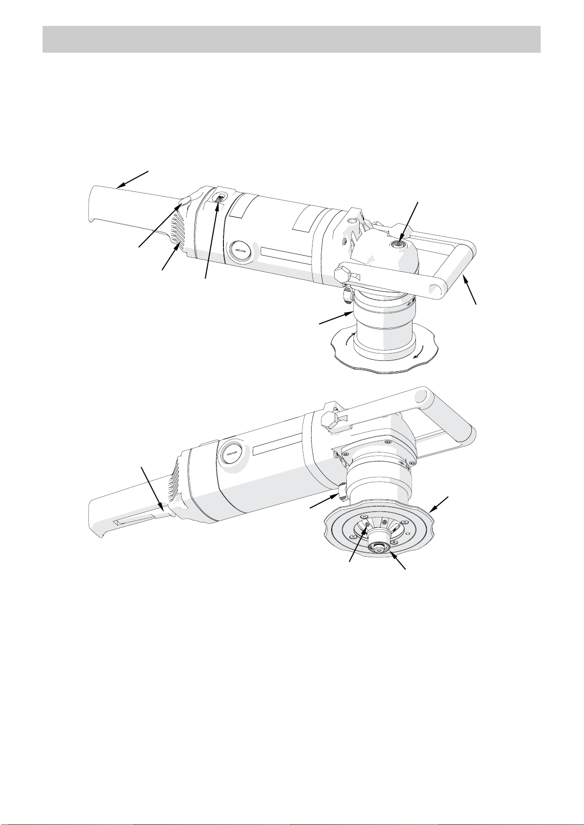
1.5. Design
Speed adjustment dial
Handle
Handle
Spindle lock button
Switch lock
ON/OFF switch
Guide
Clamping
screw
Milling head
Guiding roller
Sleeve
Air vents
Table of contents
Other Trademaster Power Tools manuals


