TradeWeld TIG 200 DC User manual
1

2
CONTENTS
Contents & Explanation of Symbols ······················································································2
Safety Warning & Duty Cycle Explained ·················································································3
Machine Description & Technical Specification ·······································································4
Accessories ·······················································································································5
Installation & Operation ·······································································································6
Front Panel layout & TIG Welding Tips···················································································7
Operating Precautions·········································································································8
Maintenance·······················································································································9
Troubleshooting & Fault Finding & TIG Welding······································································10
TIG 200D Explosion Diagrams & Part List···············································································11
Warranty & Owners Records·································································································12
EXPLANATION OF SYMBOLS
The rating plate on your machine and/or the manual may show certain symbols.
These represent important information about the product or instructions on its use.
Conforms to relevant safety standards.
To reduce the risk of injury, user must read instruction manual.
Do not dispose of old appliances with domestic rubbish.
Wear hearing protection.
Wear eye protection.
Wear respiratory protection.
Attention.
Caution

3
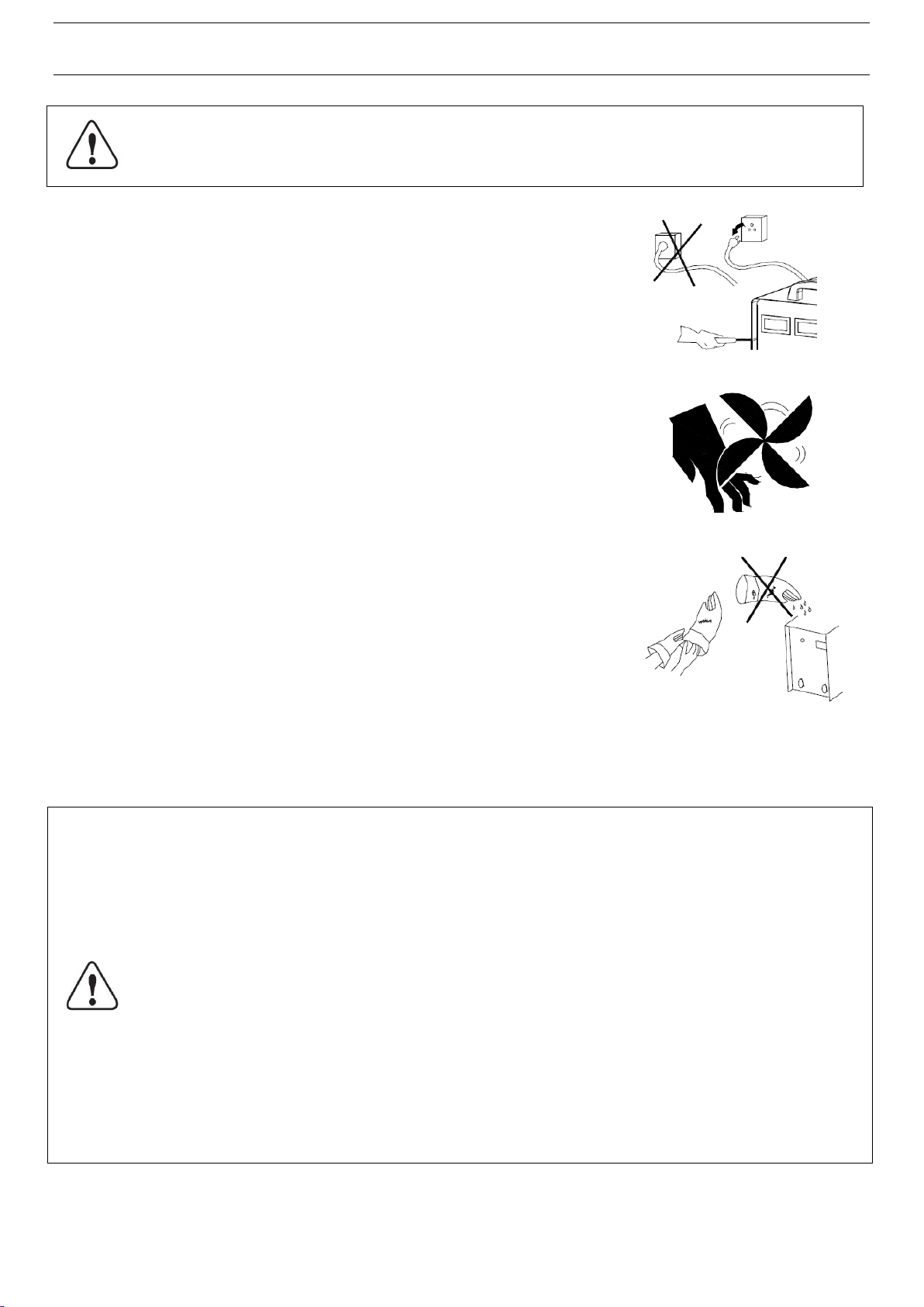
SAFETY WARNING
In the process of welding, there could be possibilities of injury, so please take
protection into consideration during operation. For more details please read the
Operator Safety Guide, which complies with the preventive requirements of the
manufacturer.
Electric shock——Can kill !
Set the earth fitting according to applying standard.
Do not touch the bare electric parts and electrode with uncovered skin, wet gloves or clothes.
Make sure you are insulated from the ground and the work piece.
Think safety first.
Gases and fumes——May be a health hazard!
Keep your head out of the gases and fumes produced by welding.
When welding, ventilators or air extractors should be used to avoid breathing in the gases.
Wear suitable respiratory protection
Arc rays——Harmful to your eyes and will burn your skin.
Wear suitable protective mask, light filter and protective garment to protect eyes and body.
Prepare suitable protective mask or curtain to protect bystanders.
Fire——Fire extinguishing equipment kept nearby!
Cutting spark may cause fire, make sure there are no flammable materials or liquids around the working area.
Noise——Excessive noises will be harmful to your hearing.
Use ear protector or others means to protect ear.
Warn bystanders that noise is harmful to hearing.
Malfunction——Use qualified technician to repair machine.
If faulty during installation and operation, please follow this manual instruction on fault finding.
If you fail to fully understand the manual, or fail to solve the problem with the instructions, you should contact the
suppliers or the service centre for professional help.
DUTY CYCLE 60%
Duty Cycle is a percentage of 10 minutes that the unit can weld at rated load without overheating. If unit overheats,
thermostat(s) opens, output stops and the cooling fan runs. Wait fifteen minutes for unit to cool down. Reduce
amperage, or duty cycle before welding again.
Exceeding the duty cycle can damage the machine and void the warranty
CAUTION
WORKING LONGER THAN RATED DUTY CYCLE
CAN DAMAGE MACHINE AND VOID WARRANTY

4
MACHINE DESCRIPTION
Thank you for purchasing a TRADEweld product. The TRADEweld TIG 200 DC Inverter is
manufactured to the highest standards.
Adopting the most advanced inverter technology, it uses power Inverters and PWM technology,
which works by rectifying the mains AC input voltage. The rectified input voltage is then inverted
and filtered to a smooth DC current. The smoothed DC current is then sent through power
switches (Mosphets) which convert it back to a high frequency AC voltage. The AC voltage is then
stepped down by a transformer and rectified to DC. The rectified DC is then filtered and smooth for
a usable power output for welding.
The development of inverter welding equipment has massive benefits which include greatly
reduced size and weight, greater power efficiency, multi-process capabilities and many more. The
inverter welder’s power source produces a much stronger and concentrated stable arc which
results in better quality and more efficient welds.
With the High frequency and gas valve added to the inverter welding machine, it makes TIG
welding easer to master.
The TIG 200D is a constant current DC MMA & TIG inverter welder. It can TIG weld stainless steel,
carbon steel, copper, and can also be used for standard arc (MMA) welding.
TECHNICAL SPECIFICATIONS
MODEL
TIG 200D
Rated Input Voltage
AC220V±10%
1Phase
Frequency(Hz)
50/60
Input Current ( A )
TIG
MMA
28
38.1
Output voltage (V)
TIG
MMA
18
27.2
Output Current (A)
TIG
MMA
10 –200
30 –180
No load Voltage DC (V)
50-80
VRD (Volt safe)
Yes - 20V
High Frequency Start
yes
Duty Cycle
60%
Efficiency(%)
80
Power Factor
0.73
Protection Class
IP21
Dimension L x W x H (mm)
465×345×360
Weight (kg)
13.6
5
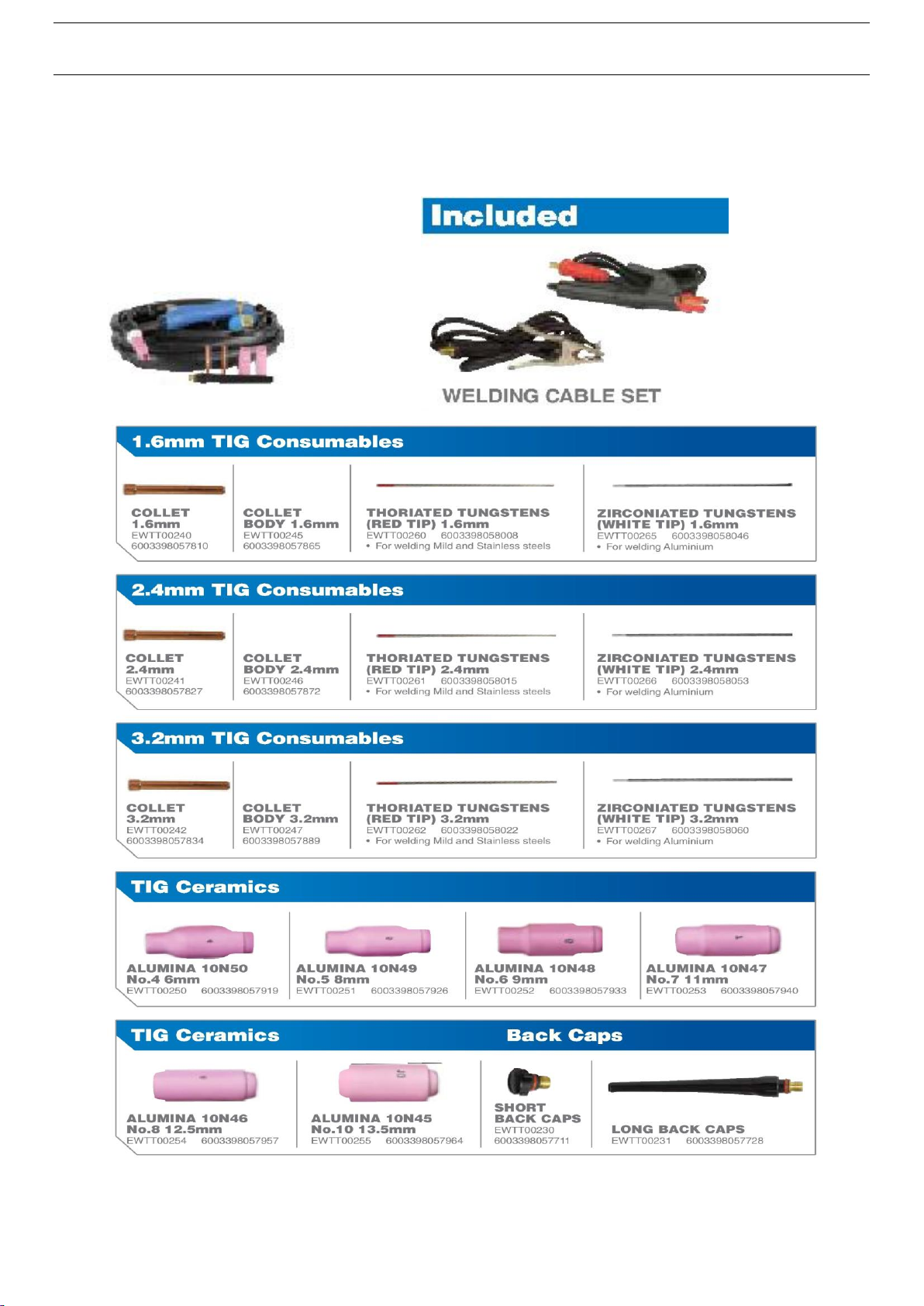
ACCESSORIES & CONSUMABLES
Supplied with the TIG 200D in the box is the following:
1 x WP17 torch 1 x earth clamp and cable
1 x 2m gas pipe 1 x electrode holder and cable
2 x hose clamp
WP17 TIG TORCH
EWTT00200

6
INSTALLATION
1. MMA: The electrode holder and earth clamp are easily connected to the machine by inserting the quick connector
and twisting it clockwise. Always ensure a tight fit. Please pay attention to the connection polarity.
Generally, Reverse Polarity is used in which the welders electrode holder will be connected in the “+” Positive
Terminal while the earth clamp in the “-”Negative Terminal. The welder does have the ability to be used for
Straight Polarity or Reverse Polarity. We recommend you connect the polarity in accordance with the electrode
recommendations. If the polarity is connected incorrectly it will cause an unstable arc, spatter, and/or the electrode
to stick. If these symptoms occur change the polarity.
2. TIG torch: Fit the gas and power cable nut to the center connector on the front panel, and fasten clockwise and
the trigger plug to the front panel; connect the earth cable quick connector to the right side dinse connector.
3. Connect the Gas hose to the back of the machine and to the Argon regulator and fit the regulator to an Argon gas
bottle. (NB: Secure the gas bottle to a gas trolley or wall to prevent falling over)
4. Turn the machine on via the ON OFF switch located at the rear of the machine, digital current meter is on, fan
begins to rotate.
NB: When TIG welding disconnect the electrode holder or when MMA welding disconnect the TIG torch.
OPERATION
MMA:
1. On the front panel select MMA process.
2. Adjust welding current and make sure the welding current is adequate for the thickness of the material.
3. Strike an arc by touching the electrode to the work piece.
TIG:
1. On the front panel select TIG process.
2. Open the valve of the argon gas cylinder and adjust the flow rate to 10 –15 LPM Liters per minute.
3. Select the gas post flow of 2 or 5 seconds. (2s - for short or low amperage welds, 5s for long or high amp welding)
4. Press the switch on torch, the gas valve clicks and HF can be heard in the machine, at the same time Argon gas
will flow from the TIG torch. NOTES: Trigger the torch to disperse air out the pipes and to let the Argon gas flow
through. After welding Argon gas will still flow out for several seconds (Post flow) in order to protect the welding
spot and to cool the tungsten.
5. Adjust welding current and make sure the welding current is adequate for the thickness of the material.
6. The welding tungsten is held 2 to 4mm away from the material, press the torch trigger an arc will jump from the
tungsten to the work piece striking an arc the HF sound will stop. DC TIG welding is very quiet weld.
ELECTRODE CHART GUIDELINE
TIG CHART GUIDELINE
1.6mm Thoriated Tungsten
2.4mm Thoriated Tungsten
3.2mm Thoriated Tungsten
10 –120 A
80 –180 A
150 –320 A
Electrode size
6013
2.0 mm
2.5 mm
3.2 mm
4.0 mm
5.0 mm
Amperage
50 –80 A
60 –100 A
100 –140 A
150 –210 A
200 –280 A
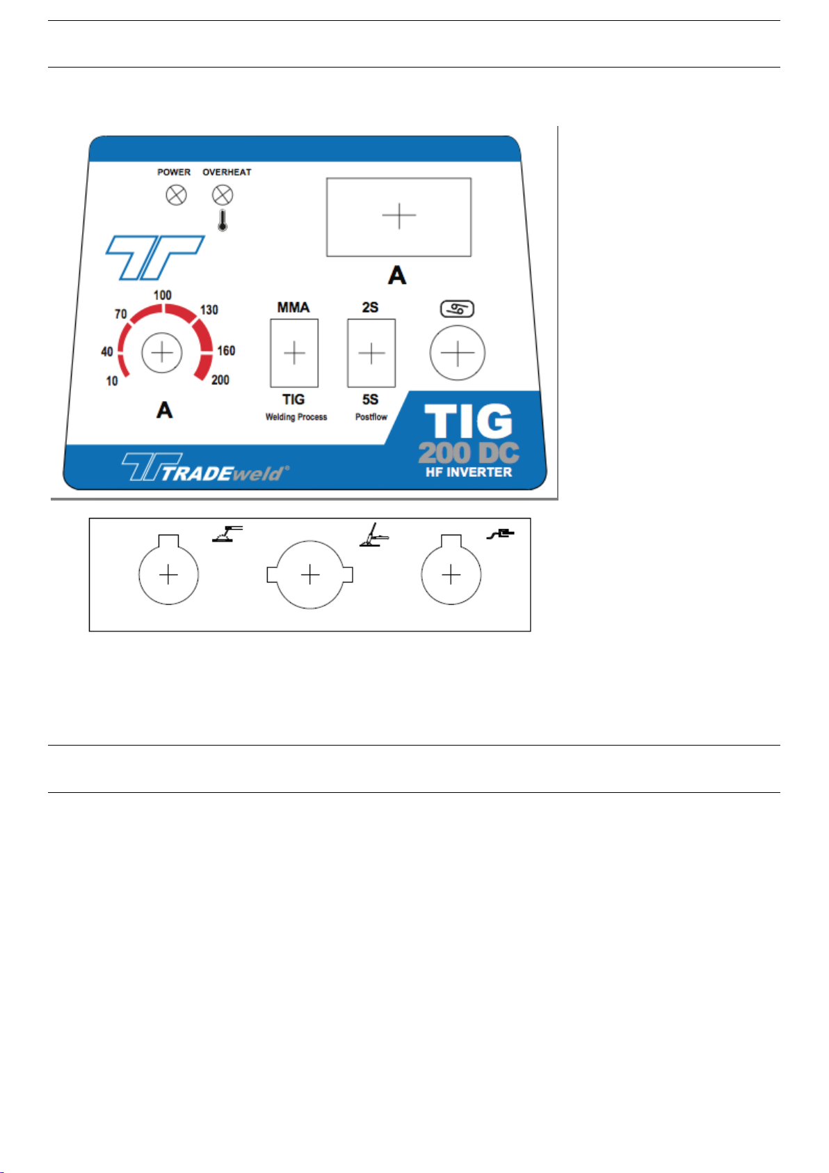
7
FRONT PANEL LAYOUT TIG 200D
TIG WELDING TIPS
Sharpen tungsten point length to 1.5 times the thick ness of the tungsten.
Make sure grinding marks are in line with the tip.
Weld in the same direction the gas is flowing. (Leaves smoke marks if pulling)
Dip the filler rode in front of the pool (in front of direction you are moving)
Practice on same type material you are going to weld on.
If tungsten burns away too fast –lower the amperage or use thicker tungsten.

8
OPERATING PRECAUTIONS
1. Operating Environment
a. The machine can perform in environments where conditions are dry with a max humidity of 60%.
b. Ambient temperature should be between -10 to +40 degrees centigrade.
c. Avoid operating machine in direct sunshine, rain, or snow.
d. Avoid operating the machine in environments where there is pollution or high concentrations of dust or
corrosiveness gas in the air.
2. Proper Ventilation
All users must ensure proper ventilation of the welder. The welder is powerful and compact which generates high
currents and heat. Wind alone cannot ensure proper cooling so it is advisable to place a fan to cool down the machine
during hot weather or continuous usage in order to keep the components working for a long shelf life. Make sure the
machines vents or built-in fans are not blocked or covered and it’s receiving proper ventilation. Keep the welder at a
minimum of 30cm from any objects to ensure proper ventilation.
3. Avoid Overvoltage
The specific power voltage can be found in the main technical specification chart listed above or on the rear plate of
the machine. The automatic voltage compensation circuit will ensure that the welding current is functioning in the
correct range. If the power voltage is exceeded from the max allowed value it will damage the components of the
machine.
4. Avoid Overloading
Limit the welding current strictly to the max allowable duty cycle. Do not exceed the max load because overloading
can damage and burn up the machine.
5. Duty Cycle
Duty cycle refers to the percentage of the working time against a 10-minute work cycle. For example, if the welder has
a 60% duty cycle at 200A this means you can run the welder at 200A for 6 min in a 10 min work cycle. The remaining
4 minutes will be needed to let the machine cool down. If the welding current decreases, the duty cycle will increase
and vice versa.
Do not operate over the recommended duty cycle of the welding machines or damage will occur to the machine that is
irreversible. When output exceeds the duty cycle limit, the temperature within the welding machine will rise and the
protective circuit will cut off the power source output. The power output will then resume operation only when the
equipment has cooled down to normal temperature.
Note: Continuous overload operation will damage the welding power source. In these cases, the damage is not
covered by warranty repair.
WARNING! This machine produces an electromagnetic field during operation. This field may under some
circumstances interfere with active or passive medical implants. To reduce the risk of serious or fatal injury, we
recommend persons with medical implants to consult their physician and the medical implant manufacturer before
operating this machine.
9
MAINTENANCE
1. Remove dust with dry, clean compressed air regularly, if the welding
machine is operated in an area where the air is polluted with smoke and
dust, the machine needs to be cleaned regularly, remove dust monthly.
2. Pressure of compressed air must not be more than 5 bars in order to
prevent damage to small components inside the machine.
3. Check inside the welding machine regularly and make sure the output
terminals are connected tightly and connectors are not damaged. If burnt,
loose or damaged please tighten or replace if necessary. Beware of moving
parts.
4. Avoid water and steam entering into the machine, if the welding machine
dose get wet please dry inside the machine and check the insulation of
machine.
5. If the welding machine will not be operated for long periods it should be
put into a box or covered and stored in a cool dry area.
WARNING!
Before maintenance and checking, power must be turned off,
Before opening the cover disconnect the machine from electricity!
WARNING!
This machine is mainly used in the welding industry. It will produce Electric
& Magnetic fields, so the operator should insure proper protection/screening
is used
Earth leakage-circuit breaker should be used with this machine!!!
During welding, DO NOT pull out or insert any plugs or cables, it can lead to
life-threatening danger and cause damage to the machine.
Before connecting cables make sure the power is off.
The correct way is to connect the cables to the machine first, and make sure
they are firmly tightened and then connect the power plug to the power
source.

10
TROUBLESHOOTING AND FAULT FINDING
Notes: only attempt to repair this machine if you have knowledge and understanding of electronic components and the
dangers of electricity and components holding a charge of high voltage electricity. Before maintenance contact us for
authorization is suggested.
DO NOT REPAIR OR MODIFY MACHINE IF STILL UNDER WARRANTY
If the machine fails to work after maintenance and checks, please contact your local distributor or our
after-sale service center.
WARNING! Experimentation and careless maintenance may lead to more
problems to the machine. This will make formal diagnostic and repair more
difficult. When the machine is open there may be exposed connections
containing life-threatening voltages. Any direct or indirect touch will cause
electric shock, and severe electric shock will lead to death.
Faults
Remedy
Porosity in the
weld
The cause of porosity is from oxygen (air) contaminating the weld. To prevent this check the
following:
1) Make sure the valve of Argon cylinder is opened and has enough pressure.
2) Check if the flow meter is opened and has enough flow .User can choose different flow
rates according to welding current in order to save gas .But too little gas flow may cause
porosity because not enough shielding gas is covering the welding spot. We suggest that
flow of argon must be kept minimum 10L/min.
3) Check if torch or gas hose is not blocked, damaged, pinched, melted or has any holes.
4) The welding material might be contaminated with oil or dirt.
5) Strong wind will lower the welding quality.
Power indicator is
not lit, fan does
not work and no
welding output
1. Make sure power switch is working.
2. Check connections from ON switch to power board are in good condition, check continuity
of ON OFF switch.
3. Check if the plug point you are using is working.
4. Check if supply voltage is correct
5. Auxiliary power board might be faulty.
6. Control board might be faulty.
Power indicator is
lit, fan works, no
welding output
1. Check if all cables are connected properly.
2. Output connector is disconnected or damaged.
3. Control circuit might be faulty.
QC (Quality
Control) indicator
is on permanently
1. Can be in overheat protection; wait for 15 minutes.
2. Maybe it is overcurrent protection, turn machine off for 30 seconds then switch on again. If
still not working there is a fault on the MOS board.
3. Mosphets on control board might be faulty.
4. Fast recovery diodes or transformer might be faulty.
Output Current is
not stabilized
1. Supply voltage is not stable.
2. 1K Potentiometer might be damaged?
3. There is harmful interference from supply voltage or other equipment?
4. Bad connections - Hot/bad connections or points on earth cable or electrode holder can
cause current to drop or be unstable.
Sound of HF
cannot be heard,
and arc welding
mode works.
1. Primary cable of H.F. transformer is not connected to power board firmly.
2. TIG / MMA Switch is damaged, replace it.
4. Check if HF control board components are damage, replace it.

11
TIG 200D EXPLOSION DIAGRAM
PART LIST TIG 200D
NO.
NAME
PART NO.
NO.
NAME
PART NO.
NO.
NAME
PART NO.
NO.
NAME
PART NO.
1
POT KNOB
EWS00013
8
GAS & POWER
CONNECTOR
EWPCB00066
16
AIR FLOW ENCLOSURE
23
SWITCH FILTER PCB
PHB-10-A
2
POT 1K/2W
EWS00014
9
OUTPUT PANEL
STICKER
17
FAN 220V
EW00101
24
LED BOARD
3
SELECTOR SWITCH
10
LEFT FOOT PAD
18
GROUND TERMINAL
25
MACHINE COVER
4
2 PIN MIC PLUG
EW0005
11
CHASIE FRAME
19
CROSS BEAMS
26
REAR PLASTIC COVER
2 PIN CABLE PLUG
EW00049
12
RIGHT FOOT PAD
20
CENTRE PCB PDB-09
EWPCB00056
27
HANDLE
5
DIGITAL DISPLAY
EWPCB00057
13
SOLENOID VALVE 220V
EW00054
TOP BOARD PMB-12
EWPCB00018
28
FRONT PLASTIC COVER
6
FRONT STICKER
14
CABLE GLAND
21
POWER BOARD PD-05
EWPCB00012
7
10-25 DINSE SOCKETS
EWC00060
15
POWER CABLE
22
ON / OFF SWITCH
EWS00017

12
WARRANTY
L&G Tool and Machinery Distributors warrant to the original purchaser only, that this product is free from
defects in material and workmanship. Subject to certain exceptions, L&G Tools & Machinery Distributors will
repair or replace any part on this product which, after examination, is determined by us to be defective in
material or workmanship for a period of twelve (12) months after the date of purchase unless otherwise noted.
Return of the product and all its accessories to the Retailer is required, together with a copy of the proof of
purchase should be included with the returned product. This warranty does not apply to damage that L&G Tool
and Machinery Distributors determines to be from repairs made or attempted by anyone other than L&G Tool
and Machinery Distributors authorized agents, misuse, alterations, abuse, normal wear and tear, lack of
maintenance, or accidents. This warranty does not include items considered as consumables.
Statutory Rights
This warranty is in addition to and in no way affects your statutory rights
Distributed
by
L&G Tool
&Machinery Distributors Limited
6
Kyalami Rd Westmead 3610 P.O. Box 15313 Westmead 3608 Telephone: 031-7176800, Fax:
031-7176868
OWNER’S RECORD
Please complete and retain with your personal records.
Model Name: Serial Number:
Purchase Date: (Date which equipment was delivered to original customer)
Distributor: Invoice Number:
Address:
City:
Country: Postal:
This manual suits for next models
1
Table of contents
Other TradeWeld Welding System manuals


Popular Welding System manuals by other brands


Lincoln Electric
Lincoln Electric PRO-CUT IM637-A Operator's manual

HURNER
HURNER HST-S-315 2.0 user manual

INNO Instrument
INNO Instrument IFS-10 user manual

Miller
Miller Millermatic 250X owner's manual

CEVIK PRO
CEVIK PRO CE-TITANCEL 210 instruction manual

Telwin
Telwin TECHNOMIG 240 WAVE instruction manual


