TradeWind International PMM Manual

INSTRUCTION
AND OPERATION
MANUAL
PMM* – Mini Modulator
Pace Electronics tel 800 444 7223 fax 507 288 www.pacemso.com

2 PMM* – Mini Modulator Instruction and Operation Manual
PMM* – Mini Modulator Technical Data
DESCRIPTION:
Professional quality channelized heterodyne audio/video modulator with SAW filter for adjacent
channel capability. The PLL oscillator with micro-processor can control the output frequency to
meet FCC required accuracy and off setting.
FEATURES:
Die cast housing
SAW Filtered for superior vestigial side band shaping and harmonic
reduction
Microprocessor controlled frequency setting meet all FCC accuracy and
off setting requirement
Upgrade to stereo with an optional stereo encoder card (PMM-SEC2)
Channel can be reset within its band resetting dip switch and output
filter only
Factory upgradable for composite stereo with additional Stereo
Encoder Card (PMM-SEC2)
Channels 2-92, listed on the front and rear
41 dBmV output
3 year limited warranty
SPECIFICATIONS:
•
•
•
•
•
•
•
•
•
Input Level:
Video
Audio
0.9Vp-p min for 87.5% modulation
0.25Vp-p for 25KHz peak deviation
Input Impedance:
Video
Audio
75 Ohm, F connector
10K Ohm, RCA Jack
Video S/N -60 dB Minimum (weighted)
Input Level Range: 0.75Vp-p - 1.5Vp-p
Differential Phase: <5º
Differential Gain: <5%
Pre-Emphasis 75 µ sec
Flatness: 1.5 dB, 50Hz - 15Hz
Output Channel:
Cable:
UHF:
Ch. 2 - Ch. 135
Ch. 14 - Ch. 69
Output Level: 41 dBmV min. with 20dB
level control
Output Impedance: 75 Ohm
Operating Temperature: -10ºC to 50ºC
Power: 12VDC, 5V

3 PMM* – Mini Modulator Instruction and Operation Manual
PMM* – Mini Modulator Physical Dimensions
FRONT PANEL
1. Power On Indicator: The LED indicates unit is powered on and operating.
2. Video Modulation: Used to set the video input level attenuation prior to modulation
3. Audio Modulation: Used to set the audio input level attenuation prior to modulation.
4. A/V Ratio: Adjusts the level of the audio RF carrier in proportion to the.
5. RF Output Level: Adjusts the RF output level to balance the modulated output at 41
dBmV.
WARNING: Adjusting the mini modulator RF output to operate higher than the rated 41 dBmV will
reduce the lifetime of the product and may damage the modulator. For a higher power output to
the system consider using active combiners or distribution amplifiers.
REAR PANEL
6. Video In: This “F” connector accepts composite video input from a satellite receiver, DVD
player or other equipment.
7. Audio In: The audio from the satellite receiver or DVD player is connected to these RCA
connectors. The audio inputs are combined into a mono-aural signal unless a stereo
encoder card is installed in the modu-lator.
8. RF Out: The modulated output signal comes out of this “F” connector to the combiner.
9. Power Plug: The three-pin power plug connects to a modulator power supply with 5 and
12VDC.
AUDIO
MOD
VIDEO
IN
AUDIO
IN
1
2
3
4
5
PMM
VIDEO
MOD
A/V
RATIO
RF OUT
LEVEL RF
OUT
POWER POWER
CH.
3
3
6
9
10
8
7
37/8” 23/4”
1” 0.63”

4 PMM* – Mini Modulator Instruction and Operation Manual
CATV (STD) 0 = ON
L 1
CH OSC V 1234567 8
2 101 55.25 0 0 0001 0 0
3107 61.25 0 0001 1 00
4113 67.25 0000001 0
L 2
5 123 77.25 0 0001 0 10
6129 83.25 0000011 0
H
7 221 175.25 0 00 0 1110
8227 181.25 00 0 0000 1
9233 187.25 0 0 0010 0 1
10 239 193.25 1 0 0 0 0 0 0 0
11 245 199.25 1 0 0 0 1 0 0 0
12 251 205.25 1 0 0 0 0 1 0 0
13 257 211.25 1 0 0 0 1 1 0 0
M
14 167.0125 121.2625 1 0 0 0 0 0 1 0
15 173.0125 127.2625 1 0 0 0 1 0 1 0
16 179.0125 133.2625 1 0 0 0 0 1 1 0
17 185 139.25 1 0 0 0 1 1 1 0
18 191 145.25 1 0 0 0 0 0 0 1
19 197 151.25 1 0 0 0 1 0 0 1
20 203 157.25 0 1 0 0 0 0 0 0
21 209 163.25 0 1 0 0 1 0 0 0
22 215 169.25 0 1 0 0 0 1 0 0
S 1
23 263 217.25 0 1 0 0 1 1 0 0
24 269 223.25 0 1 0 0 0 0 1 0
25 275.0125 229.2625 0 1 0 0 1 0 1 0
26 281.0125 235.2625 0 1 0 0 0 1 1 0
27 287.0125 241.2625 0 1 0 0 1 1 1 0
28 293.0125 247.2625 0 1 0 0 0 0 0 1
29 299.0125 253.2625 0 1 0 0 1 0 0 1
S 2
30 305.0125 259.2625 1 1 0 0 0 0 0 0
31 311.0125 265.2625 1 1 0 0 1 0 0 0
32 317.0125 271.2625 1 1 0 0 0 1 0 0
33 323.0125 277.2625 1 1 0 0 1 1 0 0
34 329.0125 283.2625 1 1 0 0 0 0 1 0
35 335.0125 289.2625 1 1 0 0 1 0 1 0
36 341.0125 295.2625 1 1 0 0 0 1 1 0
HY 1
37 347.0125 301.2625 1 1 0 0 1 1 1 0
38 353.0125 307.2625 1 1 0 0 0 0 0 1
39 359.0125 313.2625 1 1 0 0 1 0 0 1
40 365.0125 319.2625 0 0 1 0 0 0 0 0
41 371.0125 325.2625 0010 1 000
42 377.025 331.275 0 01 0 0100
43 383.0125 337.2625 0 0 1 0110 0
44 389.0125 343.2625 0 0 10001 0
45 395.0125 349.2625 0 0 1010 1 0
46 401.0125 355.2625 0 0100 1 10
47 407.0125 361.2625 0010 1 11 0
48 413.0125 367.2625 00100001
HY 2
49 419.0125 373.2625 00 1 0100 1
50 425.0125 379.2625 1 0 1000 0 0
51 431.0125 385.2625 1 01010 0 0
52 437.0125 391.2625 1 0100 1 0 0
53 443.0125 397.2625 1010 1 10 0
54 449 403.25 101 0 0010
HY 2
55 455 409.25 1 0101010
56 461 415.25 1010011 0
57 467 421.25 101011 1 0
58 473 427.25 101000 0 1
59 479 433.25 1 0 1 01 0 01
60 485 439.25 0110000 0
61 491 445.25 011010 0 0
62 497 451.25 0 1100 1 00
UTR
1-1
63 503 457.25 01101100
64 509 463.25 0 1100010
65 515 469.25 0 1 1 0 1 0 1 0
66 521 475.25 0 1 1 0 0 1 1 0
67 527 481.25 0 1 1 0 1 1 1 0
68 533 487.25 0 1 1 0 0 0 0 1
69 539 493.25 0 1 1 0 1 0 0 1
70 545 499.25 1 1 1 0 0 0 0 0
71 551 505.25 1 1 1 0 1 0 0 0
72 557 511.25 1 1 1 0 0 1 0 0
73 563 517.25 1 1 1 0 1 1 0 0
74 569 523.25 1 1 1 0 0 0 1 0
75 575 529.25 1 1 1 0 1 0 1 0
UTR
1-2
76 581 535.25 1 1 1 0 1 1 0
77 587 541.25 1 1 1 0 1 1 1 0
78 593 547.25 1 1 1 0 0 0 0 1
79 599 553.25 1 1 1 0 1 0 0 1
80 605 559.25 0 0 0 1 0 0 0 0
81 611 565.25 0 0 0 1 1 0 0 0
82 617 571.25 0 0 0 1 0 1 0 0
83 623 577.25 0 0 0 1 1 1 0 0
84 629 583.25 0 0 0 1 0 0 1 0
85 635 589.25 0 0 0 1 1 0 1 0
86 641 595.25 0 0 0 1 0 1 1 0
87 647 601.25 0 0 0 1 1 1 1 0
88 653 607.25 0 0 0 1 0 0 0 1
UTR
2-1
89 659 613.25 0 0 0 1 1 0 0 1
90 665 619.25 1 0 0 1 0 0 0 0
91 671 625.25 1 0 0 1 1 0 0 0
92 677 631.25 1 0 0 1 0 1 0 0
93 683 637.25 1 0 0 1 1 1 0 0
94 689 643.25 1 0 0 1 0 0 1 0
FM
95 137 91.25 1 0 0 1 1 0 1 0
96 143 97.25 1 00 1 0 1 10
97 149 103.25 1001111 0
98 155.025 109.275 100100 0 1
99 161.025 115.275 1 0011001
UTR
2-1
100 695 649.25 01010000
101 701 655.25 010110 0 0
UTR
2-1
102 707 661.25 0101010 0
103 713 667.25 0 1 0 11 1 0 0
104 719 673.25 0101001 0
105 725 679.25 010110 1 0
106 731 685.25 0 1010 1 10
PMM* – Dip Switch Settings

5 PMM* – Mini Modulator Instruction and Operation Manual
IMPORTANT
WARNING: This product is not WATERPROOFED. To reduce risk of electrical shock, fire hazard, or
damage to the unit, do not expose to rain or moisture.
CAUTION: To prevent electric shock, do not connect power supply until the power connections to
the modulation have been made.
NOTE TO INSTALLER: This reminder calls the system installer’s attention to Article 820-22 of the
NEC that pro-vides guidelines for proper grounding and, in particular, specifies that the cable
ground shall be connected to the grounding system of the building, as close to the point of cable
entry as practical.
HEADEND BALANCING
1. Let the headend warm up or “Burn-in” for at least 2 hours prior to calibrating.
2. Connect a calibrated RF signal meter or spectrum analyzer to the output of the highest
channel modulator.
3. Verify that the modulator is at 41 dBmV after the warm up time.
4. Connect modulator to the combiner.
5. Connect the RF signal meter or spectrum analyzer to the output of the headend. This
may be the combiner output or a distribution amplifier output.
6. Measure the highest channel to obtain the headend output level.
7. Keep the highest channel unchanged and attenuate the lower channels to match the
highest channel by reducing their RF Modulation output adjustment.
8. Fill headend balancing certificate with the headend output level, date, and signature.
9. Place the balancing certificate visible at the headend location.

Certificate of Calibration
I certify that this headend system at
has been burned, balanced, and tested in full working order in compliance with
the manufacturer balance specifications. This calibration is valid for a period of
twelve months.
Channels/Lowest/Highest
Burn-in Time hours
Headend Output Level dBmV
Measurement instrument used was calibrated on
Balanced by:
Name:
Company:
Address:
Phone:
Signature Date
Table of contents
Popular Modulator manuals by other brands

Net Media
Net Media MicroModulator MM70 Specifications
Promax
Promax DT-101B Quick configuration guide
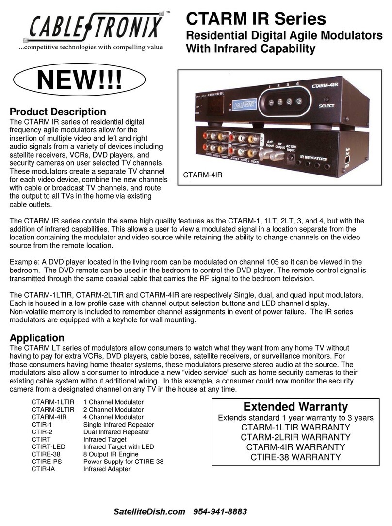
Cable-Tronix
Cable-Tronix CTARM IR Series quick start guide
Pico Macom
Pico Macom PFAM550 Installation and operation manual
Pico Macom
Pico Macom F860 Installation and operation manual
Texas Instruments
Texas Instruments UM138l operating guide
