TRADIM 631042 User manual

BENODIGD GEREEDSCHAP:
•Kleine kruiskopschroevendraaier • Kleine platte schroevendraaier • Striptang
LET OP! STEEK NOOIT DE STEKKER IN HET STOPCONTACT ALS DE DIMMER NOG
NIET VOLLEDIG AFGEMONTEERD IS! KANS OP ELEKTRISCHE SCHOK!
De fabrikant en/of leverancier is niet aansprakelijk voor schade veroorzaakt door verkeerd gebruik of onjuiste installatie van de dimmer.
De garantieperiode is 2 jaar na aankoopdatum, aan te tonen bij de vakhandelaar d.m.v. uw aankoopbon.
Versie NL 1.0 (16/2/22). Bewaar deze handleiding goed voor (her)installatie!
TRADIM Aalsbergen 9, 6942 SE Didam NL www.tradim.nl
Stelschroef
Indicatie-led
Snoerisolatie
1
2
3
4 Aderdoorsnede
Aansluitschema
Trekontlasting
Schuif
5
6
7
15 mm
5 mm
3
4 min.
0,75 mm2naar lamp
Input
naar stopcontact
7
2
7
5
1
6
1-
+
2
GEBRUIKSAANWIJZING VLOERDIMMER 230V LED 631042
(L) bruin
Deze vloerdimmer 1-100W/VA is geschikt voor het dimmen van de volgende lichtbronnen:
•Dimbare led lampen (230V, max. 70W).
•Laag voltage led lampen gecombineerd met dimbare led drivers (max. 80W).
•Gloei- en halogeenlampen (230V, max. 100W).
•12V halogeenlampen in combinatie met dimbare elektronische trafoʼs (max. 80W).
KARAKTERISTIEKEN VAN DEZE VLOERDIMMER:
•De dimmer heeft een stelschroef voor het instellen van de minimale dimstand.
•De µ op de sticker geeft aan dat er in de uit-stand géén spanning op de lamp staat.
•De indicatie-led (tekening 2) geeft aan dat de dimmer aan staat.
•Uitsluitend binnenshuis gebruiken bij een temperatuur tussen 0-40ºC.
A. AANSLUITEN VAN DE DIMMER:
1. Haal de stekker van de lamp uit het stopcontact.
2. Strip de draden (ader doorsnede minimaal 0,75mm²) voor zowel de lamp als de voeding (tekening 3 en 4)
3. Schroef de dimmer open en neem het binnenwerk (printplaat) uit de behuizing.
4. Steek de gesplitste bruine en blauwe draden van de stekker en lamp op de aangegeven plek van het aansluitblokje
(tekening 5) en draai de schroeven aan. Indien er een aarde (geel-groene) draad aanwezig is, deze op het middelste
contact aansluiten.
5. Plaats het binnenwerk, inclusief snoeren, terug in de behuizing en zorg dat de schuif onderin staat.
6. Bij gebruik van een plat snoer, deze stap overslaan. Bij gebruik van een rond snoer de trekontlastingen uit de
bovenzijde van de dimmer halen en deze omdraaien zodat de korte zijde van de trekontlastingen op de kabels drukken.
7. Plaats de bovenzijde terug ‒ let hierbij op dat de stelschroef (tekening 1) en de indicatie-led (tekening 2) in de
doorvoer passen. Zorg er ook voor dat de schuif (tekening 7) onderin staat.
8. Controleer of de schuif goed meeloopt. Zo niet, herhaal stap 7. Draai de 4 schroeven terug in de behuizing.
B. INSTELLEN VAN DE MINIMALE DIMSTAND:
9. Stop de stekker in het stopcontact en test de werking van de dimmer.
10. Zet de dimmer aan door de schuif (tekening 7) te bewegen. De indicatie-led (tekening 2) gaat branden.
11. Duw de schuif (tekening 7) naar de minimale stand, waarbij de dimmer net niet wordt uitgeschakeld.
12. De indicatie-led (tekening 2) blijft op dit moment branden. De lampen horen in de minimale dimstand niet uit te zijn.
Indien dat wel het geval is, draai dan aan de stelschroef (tekening 1) tot de lamp aan gaat.
13. Zodra de minimale dimstand naar wens is ingesteld is de dimmer klaar voor gebruik.
WERKING VAN DE DIMMER:
De schuif (tekening 7) kan met de voet bediend worden. De indicatie-led (tekening 2) geeft aan dat er spanning op
de lamp staat. Wanneer de schuif onderin staat, zal er intern een schakelaar bediend worden die het apparaat
volledig afschakelt. Op dat moment staat er geen spanning meer op de lamp en zal de indicatie-led uit staan.
(N) blauw
(PE) geel/groen
(L) bruin
(N) blauw
(PE) geel/groen
N
PE
L
N
PE
L
Output

A. CONNECTING THE DIMMER:
1. Unplug the lamp from the wall socket.
2. Strip the wires (core diameter minimum 0.75 mm²) from both the lamp and the power supply (No. 3) and (No.
4) in the drawing above).
3. Unscrew the dimmer and remove the interior (PCB) from the housing.
4. Insert the stripped brown and blue wires of the wall plug and lamp into the relevant part of the terminal block
(No. 5) and tighten the screws. If a ground (yellow-green) wire is present, connect it to the middle contact.
5. Place the interior, including cords, back into the housing and ensure that the slide is at the bottom.
6. If using a flat cord, skip this step. If using a round cord, remove the strain reliefs from the top of the dimmer
and turn them over so that the short side of the strain reliefs press on the cables.
7. Place the top of the dimmer. Make sure that the adjusting screw (No. 1) and the indicator-led (No.2) fit into the
appropriate holes. Also make sure that the slider (No. 7) is at the bottom (test whether the slider moves along).
8. Replace the 4 screws in the housing.
B. SETTING THE MINIMAL DIMMING POSITION:
PAY ATTENTION! NEVER PLUG THE PLUG INTO THE SOCKET WHEN
INSTALLATION IS NOT FINISHED YET! CHANCE OF ELECTRIC SHOCK!
1. Insert the plug into the wall and check if it works.
2. Switch on the dimmer by moving the slider (No. 7). The indicator-led (No. 2) lights up.
3. Push the slider (No. 7) to the minimal position at which the dimmer does not completely switch off.
4. The indicator-led (No. 2) stays on. The lamps should not be off in the minimal dimming position. If the lamp
is off, simply use a screwdriver to adjust the adjustment screw (No. 1) on the dimmer until the light is on.
5. When the minimal dimming position is set as desired, the dimmer is ready for use.
The manufacturer and/or supplier is not liable for damage caused by misuse or improper installation of the dimmer.
The warranty period is 2 years from the date of purchase, to be proven with your purchase receipt to the seller.
Version EN 1.0 (16/2/22). Keep this manual safe for (re)installation!
TRADIM Aalsbergen 9, 6942 SE Didam NL www.tradim.nl
Adjustment screw
Indicator-led
Cable insulation
1
2
3
4 Core diameter
Connection diagram
Strain relief
Slider
5
6
7
15 mm
5 mm
3
4 min.
0,75 mm2
Input
2
7
1
6
-
+
To lamp
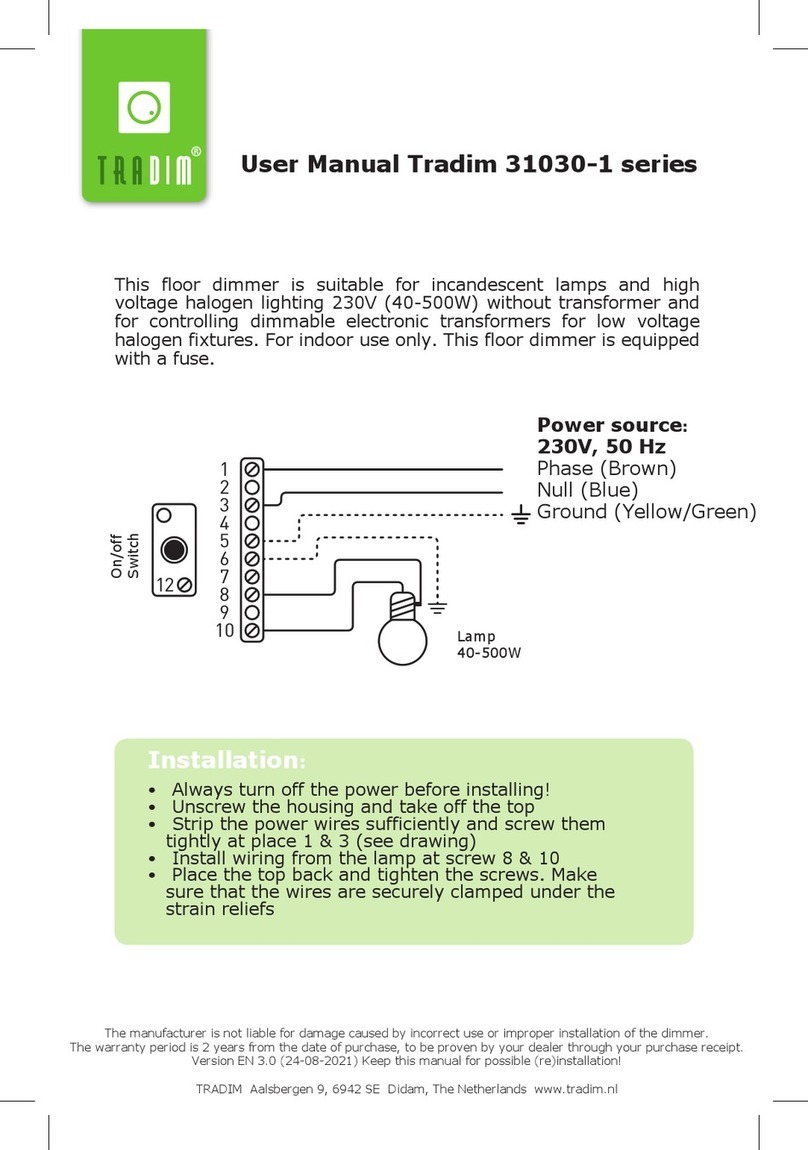
USER MANUAL FLOOR DIMMER 230V LED 631042
REQUIRED TOOLS:
•Small philips screwdriver • Small flat screwdriver • Stripping pliers
This floor dimmer is suitable for dimming the following light sources:
•Dimmable led (filament) lamps (230V, max. 70W).
•Low voltage led lamps combined with dimmable led drivers (max. 80W).
•Incandescent and halogen lamps (230V, max. 100W).
•12V halogen lamps combined with dimmable electronic transformers (max. 80W).
CHARACTERISTICS OF THIS FLOOR DIMMER:
•The dimmer has a potentiometer to set the minimum brightness.
•The µ on the sticker indicates that there is no voltage on the lamp in the off-position.
•The indicator-led (No. 2) indicates that the dimmer is on-position.
•Use indoors only and at a temperature between 0-40ºC.
OPERATION OF THE DIMMER:
The slider (drawing 7) can be operated by foot. The indicator-led (drawing 2) indicates that there is
voltage on the lamp. When the slider is at the bottom, an internal switch is operated which switches off
the device completely. At that moment, the lamp is no longer powered and the indicator-led will be off.
7 1
2
(N) blue
(PE) yellow/green
(L) brown
(N) blue
(PE) yellow/green
(L) brown
N
PE
L
N
PE
L
To plug/socket
Output
5
Table of contents
Languages:
Other TRADIM Lighting Equipment manuals
Popular Lighting Equipment manuals by other brands

LIVARNO home
LIVARNO home 1115-S manual
Fluval
Fluval T5 HO instruction manual

Signtex Lighting
Signtex Lighting Coverlite CVRAC Series installation instructions

Nexxt Solutions
Nexxt Solutions Smart Wi-Fi Galaxy Star Projector manual
e-conolight
e-conolight E-CSC Series installation instructions

Bresser
Bresser BR-80SL instruction manual
