e-conolight E-CSC Series User manual
Document: Date
Created By: ECO#
LPN00536X0001A0_A 2017-10-31
TMT 008445
INSTALLATION INSTRUCTIONS
E-CSC and E-GSC Series
www.e-conolight.com | 888.243.9445 | FAX: 262.504.5409
CAUTIONS
IMPORTANT SAFEGUARDS
When using electrical equipment, basic safety
precautions should always be followed including the
following:
READ AND FOLLOW ALL
SAFETY INSTRUCTIONS
1. DANGER- Risk of shock- Disconnect power before
installation.
DANGER – Risque de choc – Couper l’alimentation
avant l’installation.
2. This luminaire must be installed in accordance with the
NEC or your local electrical code. If you are not familiar
with these codes and requirements, consult a qualied
electrician.
Ce produit doit être installé conformément à NEC ou votre
code électrique local. Si vous n’êtes pas familier avec ces
codes et ces exigences, veuillez contacter un électricien
qualié.
3. For dimming connections use class 1 wiring methods only.
Cablage de classe 1 uniquement.
4. Suitable for Wet Locations.
Adspte pour les Endroits Mouiles.
SAVE THESE INSTRUCTIONS
FOR FUTURE REFERENCE
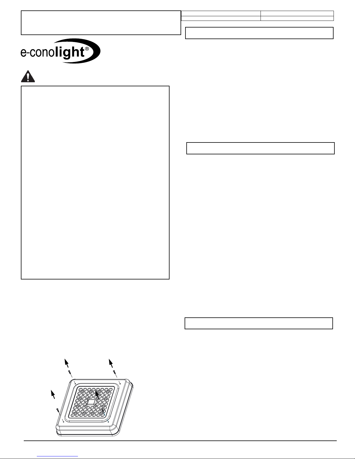
FIGURE 1
1. Remove (4) rear cover plate screws. See Figure 1.
2. Lift optic/cover assembly away from rear cover plate
3. Disconnect the two halves of the quick disconnect(s) attaching
the output leads from the driver to the optics. If equipped with an
occupancy sensor/photocell, disconnect the sensor antenna lead
from the sensor body..
4. Set the optic/cover assembly aside.
5. If equipped with an occupancy sensor/photocell, see Occupancy
Detector/ Photocell Setting section for proper setting of DIP
switches to achieve desired control.
1. Drill holes through the mounting slots in the back of the rear cover
plate as appropriate for the junction box being used.
2. For xtures installed in damp or wet locations, attach supplied
gasket to back of xture.
3. Splice leads exiting back surface of rear cover plate to leads in
junction box as indicated in Fixture Wiring section.
4. Attach rear cover plate to junction box using screws supplied by
others.
NOTE: If xture gasket was installed in Step 2, caulk between
xture and mounting surface to prevent water from entering from
behind. A high grade caulking material, such as silicone rubber,
should be used.
5. Reconnect the two halves of the quick disconnect(s) and the
sensor antenna lead that were disconnected previously.
6. Reinstall the optic/cover assembly onto the rear cover plate by
replacing the (4) rear cover plate screws.
NOTE: Fixture is intended for use with conduit having 1/2" NPT
threads.
1. Drill holes through the mounting slots in the back of the rear cover
plate to allow the plate to be attached to the mounting surface.
2. Pull leads from driver through boot covering conduit entry location
on inside surface of rear cover plate so that ends of leads are
accessible on inside of xture.
3. For xture installed in damp or wet locations, attach supplied
gasket to back of xture.
4. Feed supply leads from conduit through holes in boot covering
conduit entry point on rear cover plate.
5. Attach conduit to conduit entry location on back of rear cover
plate.
NOTE: For damp or wet locations, use of teon tape on threads of
conduit will ensure a water tight seal.
6. Attach rear cover plate to mounting surface using hardware
appropriate for mounting surface.
NOTE: If xture gasket was installed in Step 3, caulk between
xture and mounting surface to prevent water from entering from
behind. A high grade caulking material, such as silicone rubber,
should be used.
7. Splice conduit supply leads to driver leads as indicated in Fixture
Wiring section.
8. Reconnect the two halves of the quick disconnect(s) and the
sensor antenna lead that were disconnected previously.
9. Reinstall the optic/cover assembly onto the rear cover plate by
replacing the (4) rear cover plate screws.
NOTE: Fixture is intended for use with conduit or pipe having 1/2”
NPT threads.
1. Pull leads from driver through boot covering conduit entry location
on inside surface of rear cover plate so that ends of leads are
accessible on inside of xture
2. Route leads exiting end of pendant through holes in boot covering
conduit entry location.
3. Thread rear cover plate onto threaded portion of pendant.
NOTE: Teon tape should be applied to threads of pendant to
prevent water entry
NOTE: A conduit jam nut can be used to prevent xture rotation
after installation.
4. Splice conduit supply leads to driver leads as indicated in Fixture
Wiring section.
5. Reconnect the two halves of the quick disconnect(s) and the
sensor antenna lead that were disconnected previously.
6. Reinstall the optic/cover assembly onto the rear cover plate by
replacing the (4) rear cover plate screws.
PENDANT MOUNT
SURFACE MOUNT, REAR CONDUIT ENTRY
MOUNTING OVER JUNCTION BOX

Document: Date
Created By: ECO#
LPN00536X0001A0_A 2017-10-31
TMT 008445
INSTALLATION INSTRUCTIONS
E-CSC and E-GSC Series
www.e-conolight.com | 888.243.9445 | FAX: 262.504.5409
NOTE: See Figure 2 for DIP switch location on sensor body
1. See below for DIP switch settings to achieve desired control
OCCUPANCY DETECTOR/PHOTOCELL SETTINGS
(Only required for units equipped with Occupancy
Sensor/Photocell option)
Adjustable
detection area
Hold-time
Stand-by period
Stand-by
dimming level
Sensor antenna interface
Daylight threshold
Installation hol
e
1-10V
+
I – Disable*
II – 50Lux
III – 10Lux
IV – 2Lux
I – 0s
II – 10s
III – 1min
IV – 5min
V – 10min
VI – 30min
VII – 1H
VIII –
This is the time period you would like to keep at the low light output
level before it is completely switched o in the long absence of people.
This is the dimmed low light output level you would like to have after
the hold-time in the absence of people.
Stand-byperiod (tri-level control)
3
Stand-bydimminglevel
4
10%
20%
30%
50%
Disable
50Lux
10Lux
2Lux
0s
10s
1min
5min
10min
30min
1H
∞
+
I - Disable : The lamp works always,even during daylight.
II - (50 Lux)
or
III (10 Lux) : The lamp works only in twilight and in darkness.
IV - (2 Lux): The lamp works only in darkness.
I – 10%
II – 20%
III – 30%
IV – 50%*
application.
Daylightsensor
5
∞*
+
Note: “0s” meanson/o control;
daylight sensor is disabled.
8
I – 100% *
II – 75%
III – 50%
IV – 10%
Detection area can be reduced by selecting the combination on the
I – 5s
II – 30s
III – 1min
IV – 5min*
V – 10min
VI – 20min
VII – 30min
Hold-time means the time period to keep the lamp on 100%, after all
motion has ceased (detection area vacated).
Hold-time
Detectionarea
1
2
100%
75%
50%
10%
5s
30s
1min
5min
10min
20min
30min
NOTE: Detection pattern increases in size as % increases.
* Factory Settings
Settings
FIGURE 2

Document: Date
Created By: ECO#
LPN00536X0001A0_A 2017-10-31
TMT 008445
INSTALLATION INSTRUCTIONS
E-CSC and E-GSC Series
www.e-conolight.com | 888.243.9445 | FAX: 262.504.5409
CAUTION: Changes or modications not expressly approved could
void your authority to use this equipment.
This device complies with part 15 of the FCC Rules. Operation is
subject to the following two conditions: (1) This device may not cause
harmful interference, and (2) this device must accept any interference
received, including interference that may cause undesired operation.
Changes or modications not expressly approved could void your
authority to use this equipment.
This equipment has been tested and found to comply with the limits for
a Class B digital device, pursuant to part 15 of the FCC Rules. These
limits are designed to provide reasonable protection against harmful
interference in a residential installation. This equipment generates, uses
and can radiate radio frequency energy and, if not installed and used
in accordance with the instructions, may cause harmful interference to
radio communications. However, there is no guarantee that interference
will not occur in a particular installation. If this equipment does cause
harmful interference to radio or television reception, which can be
determined by turning the equipment off and on, the user is encouraged
to try to correct the interference by one or more of the following
measures:
—Reorient or relocate the receiving antenna.
—Increase the separation between the equipment and receiver.
—Connect the equipment into an outlet on a circuit different from that to
which the receiver is connected.
—Consult the dealer or an experienced radio/TV technician for help.
CAN ICES-005 (B)/NMB-005 (B)
FCC NOTICE
Fixture is equipped with universal volt driver 120-277V
(ie. 120V, 208V, 240V or 277V)
For dimming applications, Class 1 wiring methods must be
used.
PHASE TO NEUTRAL WIRING 120/277V
1. Connect supply ground to fixture ground (green) lead.
2. Connect supply common to fixture neutral (white) lead.
3. Connect supply Vin to fixture hot (black) lead.
Tuck all wires carefully into wiring chamber ensuring that no
wires are pinched.
PHASE TO PHASE WIRING 208/240V
1. Connect supply ground to fixture ground (green) lead.
2. Connect supply L1 (Hot) to fixture neutral (white) lead.
3. Connect supply L2 (Hot) to fixture hot (black) lead.
Tuck all wires carefully into wiring chamber ensuring that no
wires are pinched.
DIMMING
1. Grey and violet leads are for 0-10V dimming systems.
Cap off if not used.
2. Yellow lead is not required. Make sure cap is not
removed from end of yellow lead.
FIXTURE WIRING NOTE: Installation of glare shield requires use of E-CSC-GS glare
shield accessory.
1. Remove (4) rear cover plate screws. See Figure 1.
2. Position glare shield over optics.
3. Install clips supplied with glare shield kit under heads of screws
removed in Step 1.
4. Reinstall the optic/cover assembly onto the rear cover plate,
making sure that the clips installed in Step 3 are positioned to
properly retain glare shield.
NOTE: Installation of adapter plate requires use of E-CSC-BP-***”
or “E-GSC-BP-*** Adaptor Plate Accessory.
NOTE: Adapter plate is intended to cover an existing hole in
mounting surface up to 11" x 11" square.
1. Rear cover plate should rst be mounted to the adapter plate
using the slots in the adapter plate. Use hardware supplied by
others.
2. Mount adapter plate to the mounting surface using the four holes
in the corners of the adapter plate and fasteners appropriate for
the mounting surface.
NOTE: For damp or wet locations, caulk between xture and
adapter plate and between adapter plate and mounting surface
to prevent water from entering xture from behind. A high grade
caulking material, such as silicone rubber, should be used.
GLARE SHIELD INSTALLATION
ADAPTER PLATE INSTALLATION
This manual suits for next models
1
Table of contents
Other e-conolight Lighting Equipment manuals


Popular Lighting Equipment manuals by other brands


Cooper Lighting Solutions
Cooper Lighting Solutions Fail-Safe FCC installation instructions

Verilux
Verilux HappyLite Mini Plus VT01 user guide

marset
marset MARANGA P170 Assembly instructions
L manual")
Qlightec
Qlightec QTG50(M)L manual

Ultra-tow
Ultra-tow 40511 owner's manual

Thorn
Thorn ISARO installation instructions