Traeger 9352-USB User manual
MPI-USB user manual 1 / 93 2022/01/21 01:28
MPI-USB user manual
Art.Nr. 9352-USB
Art.Nr. 9352-USB.05M
documentation of version XX
1 Description
The MPI-USB cable connects the computer via USB with a MPI interface (9 pin interface of the PLC).
2 System requirements
2.1 Operating system(s)
Windows
10
8
7
Vista
XP
ME/2000/NT
2.2 Software
PLC - programming software (eg. PG2000, Step © 7, S7 for Windows, Microwin)
Direct driver for Simatic-Manager for USB PLC - VCOM Software
A video description of the installation of direct-driver and how to configure it can be found on the page
MPI-USB user manual 2 / 93 2022/01/21 01:28
support!
2.3 Hardware
USB 1.1 - Type A
2.4 Provided PLCs
S7-200 S7-300 (provides baud rates up to 12M (when the PLC is able to support this)
S7-400 (provides baud rates up to 12M)
FM-devices Sinamix (Step7-direct-driver up V1.20 or PLCVCom up V2.71)
MicroMaster and other electrical drives and inverter-feds (Step7-direct-driver up V1.20 or PLCVCom up
V2.71)
Sinumerik (only PLC-side)
SEW-EURODRIVE power inverter and at last routing of S7-PLCs
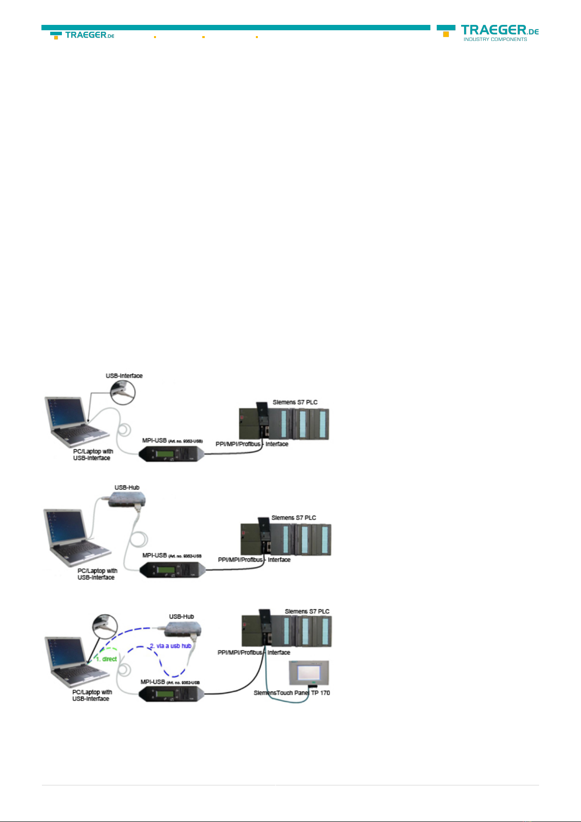
3 Connecting options
MPI-USB directly connected to the PC.
MPI-USB to the PC via a USB hub.
MPI-USB connectivity with the operator terminal
MPI-USB user manual 3 / 93 2022/01/21 01:28
4 Installation
4.1 Hardware
The S7/MPI-USB is plugged directly into the PLC. Via the USB cable of the module can be connected to the
PLC as follows:
Normal installation (for programming)
The MPI cable will be connected to the S7 PLC via the 9 pin connector (short side of the cable). The USB
connector on the long side of the cable will be connected with the computer.
S7/MPI-USB as HMI (Human Machine Interface) – adapter
The HMI – function provides the possibility to connect a operator panel (which has instead of a MPI
interface a USB device and understands the HMI protocol) with a S7 PLC (300/400). Connect the cable
between the terminal and the PLC. The HMI - protocol must be part of the operator panel.
There must be a serial communication with the operator panel if this op is new/used at the first time.
Therefore connect your operator panel with the serial COM interface of your computer. After the
communication has been running successfully the panel is ready to be connected to the PLC.
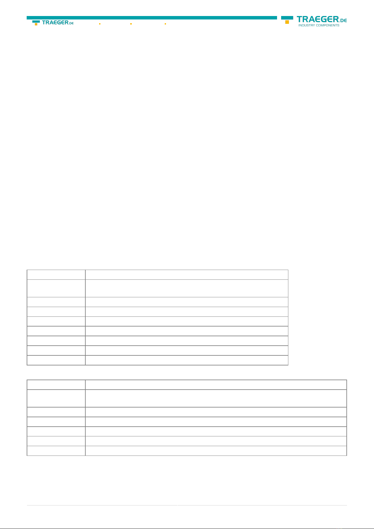
4.2 Software
To communicate with the PLC, please install following products for MPI-USB, S7-USB, MPI-II[only USB], MPI-
LAN and S7-LAN:
Product Driver
TIA-Portal TIC ⇒ “TIC ETH/USB” for MPI, PPI or PROFIBUS
configuration of driver with controll-panel ⇒ setting PD/PC-interface
Simatic-Manager TIC ⇒ “TIC ETH/USB” for MPI, PPI or PROFIBUS
Starter-Software TIC ⇒ “TIC ETH/USB” for MPI or PROFIBUS
MicroWin TIC ⇒ “TIC ETH/USB” for PPI and S7-22x-PLC
MicroWin PLCVCom for S7-21x-PLC (no MultiMaster-protocol)
PG-2000 PLCVCom or for S7-LAN/MPI-LAN direct in interface-settings
S7 for Windows TIC ⇒ “TIC ETH/USB” for MPI or PROFIBUS over PD/PC-interface
S7 for Windows PLCVCom
To communicate with the PLC, please install following products for MPI/PPI and MPI-II[only serial]:
Product Driver
TIA-Portal no support because Siemens has taken out the serial support in the driver “PC-
Adapter”
Simatic-Manager included driver “PC-Adapter” for MPI and PROFIBUS
Starter-Software included driver “PC-Adapter” for MPI and PROFIBUS
MicroWin included driver “PC/PPI-cable”
PG-2000 Standard-function, configuration in the interface-settings
S7 for Windows Standard-function, configuration in the interface-settings
MPI-USB user manual 4 / 93 2022/01/21 01:28
4.3 USB-driver-installation for 32-bit-systems
The S7-Interface S7-USB, MPI-USB or MPI-II-Kabel over USB as well as the devices of TeleService-familiy will
be connected to USB 1.1-compatible port of the PC.
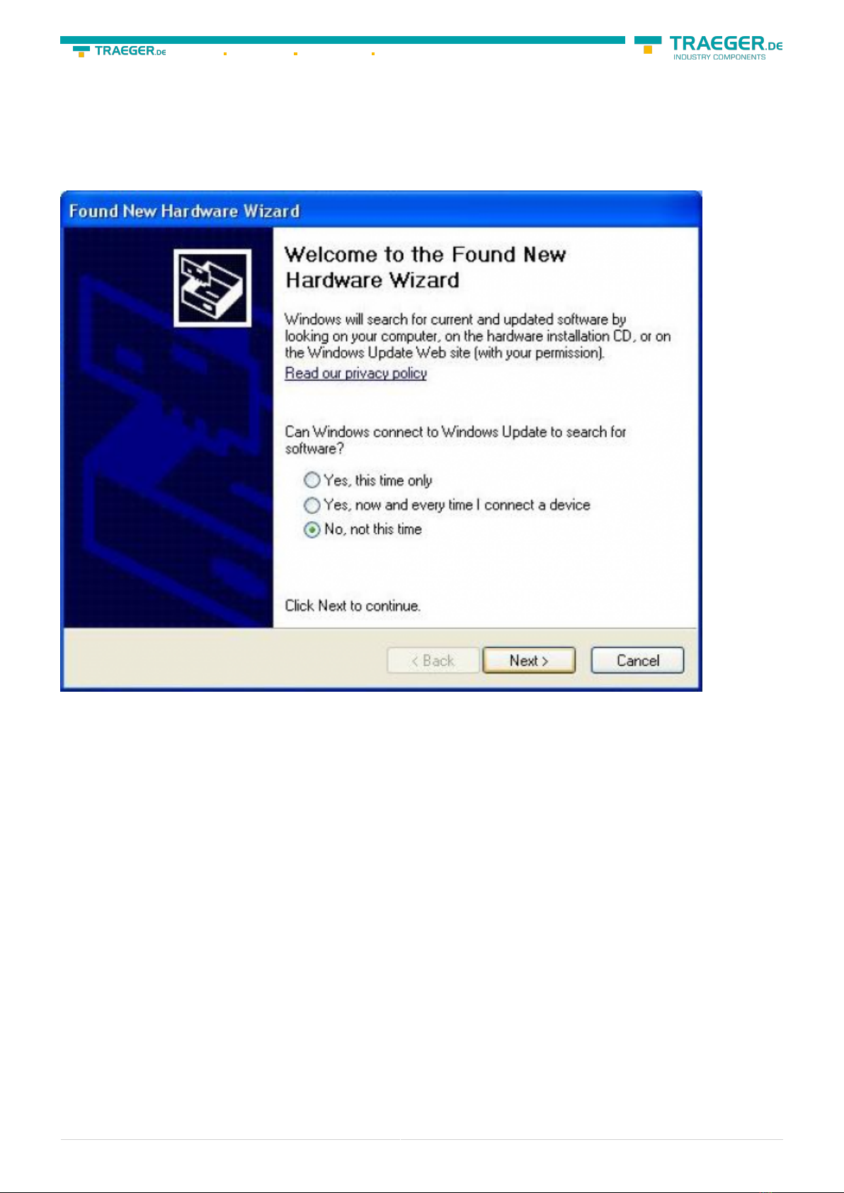
This opens the Hardware-Installation-Wizard:
We don´t need a connection to Windows update.
Select now “Install from a list or specific location”:


MPI-USB user manual 8 / 93 2022/01/21 01:28
Will this entry in the device manager shown with a “yellow exclamation mark”, then please install the
driver again or look in the driver properties about the reason.
If the driver has to be updated, please use the function “Update …” in the driver properties:

MPI-USB user manual 9 / 93 2022/01/21 01:28
If the driver has to be deleted, please use the function “Uninstall” in the driver properties:
If you install older versions of PLCVCom, Step7-direct-driver or S7IFC, the actual usb-driver will be possible
overwritten by previous versions because it was included until 01/11/2012 in their install-shields!
4.4 USB-driver-installation for Win7 64-bit
The S7-Interface S7-USB, MPI-USB or MPI-II-Kabel over USB as well as the devices of TeleService-familiy will
be connected to USB 1.1-compatible port of the PC.
After the first plug of the device Win7 displays the message. After the first plugging the PC Win7 first logs
„Installing device driver software“ and after some time „Device driver software was not installed“. This
messages could be closed.
Please start the windows device manager in the control panel.
In the device manager would be the new device shown with a exclamation mark:


MPI-USB user manual 12 / 93 2022/01/21 01:28
Please select “Browse my computer for driver software” and define as source the folder “..\USB-Treiber-
x64”. Either in the folder where the downloaded drivers were extracted or the directory on the product CD:
After pressing “Next” the message appears of windows UAC


MPI-USB user manual 15 / 93 2022/01/21 01:28
If the driver has to be deleted, please use the function “Uninstall” and set the check-box in “Delete the
driver software for this device”:
If you install older versions of PLCVCom, Step7-direct-driver or S7IFC, the actual usb-driver will be possible
overwritten by previous versions because it was included until 01/11/2012 in their install-shields!
MPI-USB user manual 16 / 93 2022/01/21 01:28
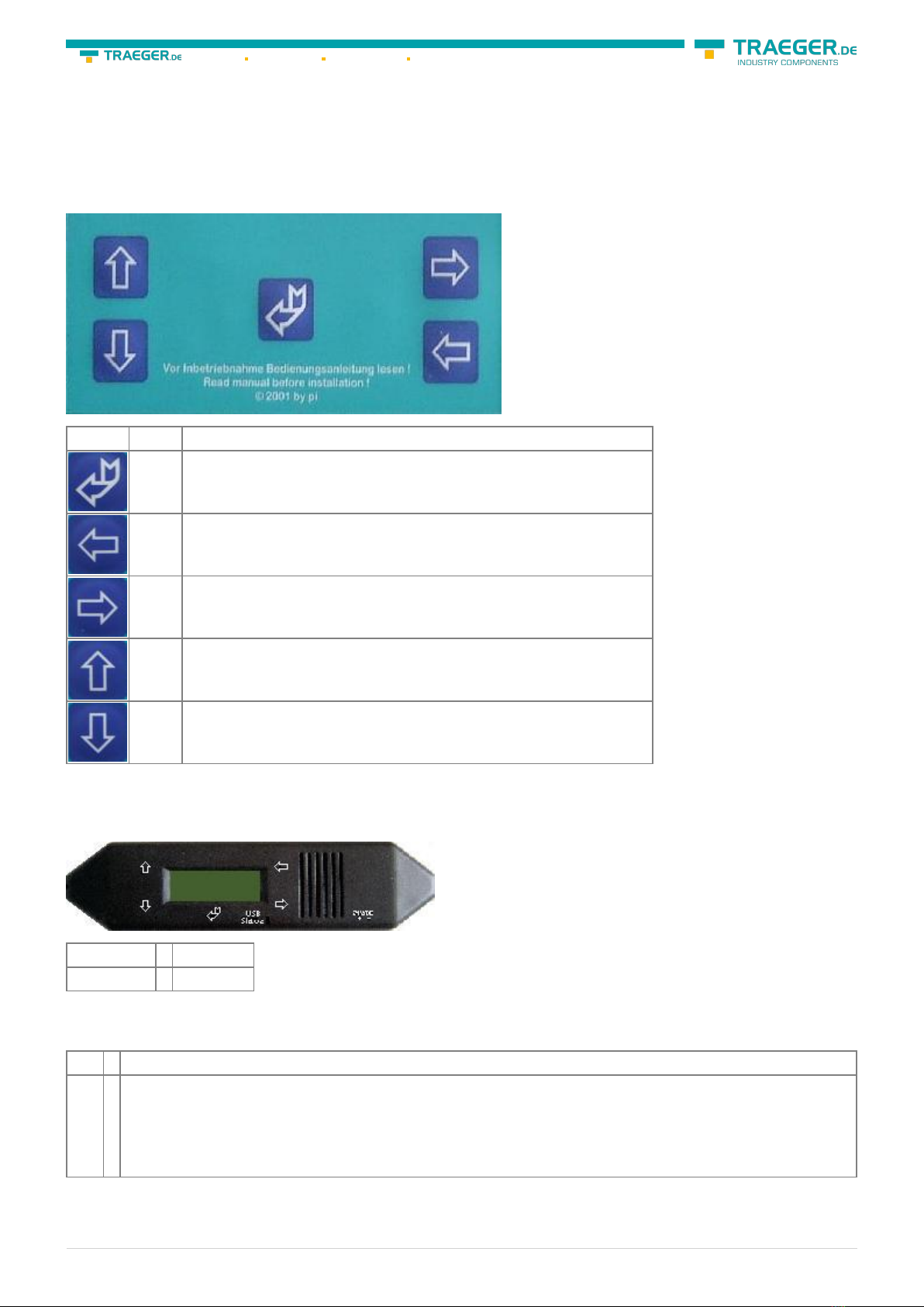
5 Control elements
5.1 Keys
Key Name Description
ENTER Change menu and confirm input.
LEFT Go one menu level back. Cancel input (Input will not be saved).
RIGHT Select sub menu.
UP Navigate upwards. Enhancement a value.
DOWN Navigate downwards. Depreciation a value.
5.2 Display
First line ⇒ #02PD00¯
Second line ⇒ !02AG04
Display description from left to right.
First line
#02 ⇒ In this example there are two active stations on the MPI – BUS
PD ⇒
letter definition of the PC - baud rate. Display Descriptions PD 115,2k or baud rate identification is
active. PU USB connection P? Baud rate recognition and access way active. TD 115,2k or baud rate
recognition is active. (cable is configured as TS – adapter) PG 19,2k TS 19,2k (cable is configured
as TS – adapter) Pg 38,4k Ts 38,4k (cable is configured as TS – adapter) pG 57,6k tS 57,6k (cable is
configured as TS – adapter) PM PPIMulti (187,5k)

MPI-USB user manual 17 / 93 2022/01/21 01:28
00 ⇒
the station number of the MPI – cable. (Default is „0“) (In the system configuration click on „Set
PG/PC interface“. In the following dialog click “properties”. Now you can change in the registry
card “MPI” part “station-related” the “adress” of the cable.) (In the PG 2000 software you can find
it by clicking on „Options“
„Interfaces“. Close to the bottom of the dialog you can change the „local address“
of the cable.)
¯⇒
Second Line
!⇒
(Exclamation mark) specifies the connection type to the PLC. Display Description ! Directly
connected to the PLC. ? Not directly connected to the PLC. ! (inverse) Directly connected to the PLC
with passive unit of the PLC. ? (inverse) Not direct connected to the PLC with passive unit of the
PLC.
02 ⇒
is the station number of a connected and active PLC in the MPI - BUS.
Every 750 milliseconds (a ¾ second) another user will be displayed if more then one user has been
found.
AG ⇒ The type of the protocol which is used for the cable to run up to the computer.
Display Description
AG Unknown because there is no connection or an older protocol version (before 5.0) is used.
Ag v5.1 Protocol
ag v5.0 Protocol
04 ⇒ Shows the station number of the device, which is connected in that moment with the computer
software (in this example station number 04).
Configuration specific messages:
With the following baud rate settings, the menu message changes accordingly:
Baud rate – configuration 1. line 2. line
PPI 9,6k – (PPISER96) PPISER96 ACTIVE
PPI 19,2k – (PPISER19) PPISER19 ACTIVE
PPI 187,5k – (PPIMulti) ???PM? ????
PPILAN – (PPILAN) PPILAN ACTIVE
PPIUSB – (PPIUSB) PPIUSB ACTIVE
SONDSER SONDSER 19,2 kBaud 8N1
SONDUSB SONDUSB 38,2 kBaud 7E2
Description 8N1:
8 = Data bits
N = Parity
1 = Stop bit
6 Implementing
Connect your module as described in the chapter “ Hardware installation ” to the PLC and to the
programming device or to your computer.
If you want to respond to a PLC via the module you have to comply the requirements as descript in the
chapter “system requirements” . In addition,please make sure that the module is properly connected
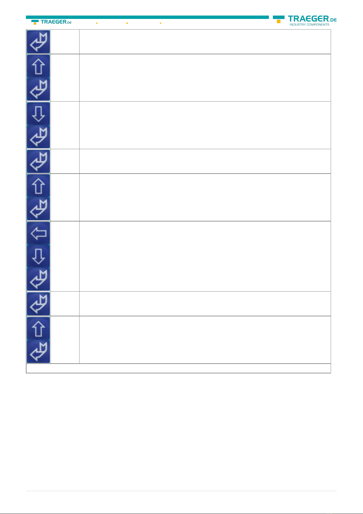
6.1 First Configuration
Key Display Description
MPI-USB user manual 18 / 93 2022/01/21 01:28
#01P?
!02AG Take the cable and press the ? key. (Control elements see chapter Control elements)).
MENU
Config Press the Up / Down-key to get to the “Config” menu and press enter.
Config
MPI-BUS Search for the submenu “MPI-BUS” and get in with enter.
MPI/PPI
Baudrate To set the baud rate configuration press enter.
MPI-Baud
Auto Navigate to the entry “Auto” and confirm your selection with enter.
Config
PG/PC Go back to the “Config” menu and navigate down to the “PG/PC” menu. Press enter.
PG/PC
Baudrate Press Enter to configure the “Baudrate”.
PG-Baud
from PC Search for the entry “from PC” and confirm with enter
The cable is now ready to work.. Go back to the menu “message” to see the status.
6.2 Using the PLC-VCOM
(The PLC-VCOM is only needed if your module is not connected via the 9 pin COM port to the computer. For
products with USB, Ethernet connection, etc., the PLC-VCOM is required)
1. Start the PLC - VCOM application (If it has not already started yet).
2. Click in the main window of the PLC-VCOM, in the status area “configure”. The configuration wizard will
start.
3. It lists all the found modules / cables and the additional information’s such as IP address and MAC
address of the module.
MPI-USB user manual 19 / 93 2022/01/21 01:28
4. Choose the desired MPI cable and click „OK“ to go on.
5. If the connection is established the chosen cable is shown in the section state and on the left side you
can see the status connected.
6. It also displays, the PLC-VCOM the IP address for the module and the IP address of the computer which
is connected to the module.
If you have any promlems with the use of PLC-VCOM software, go to the chapter PLC – VCOM and look
there for operating instructions.
6.3 Programming software to use with direct
access
After you have adjusted and connected the PLC-VCOM or the programming adapter to the COM-port on
your computer, you will be able to connect with your programming software to the PLC and work with it.
How you have to adjust your programming software is described in the following points:
6.3.1 PG2000 für S7 (V5.10)
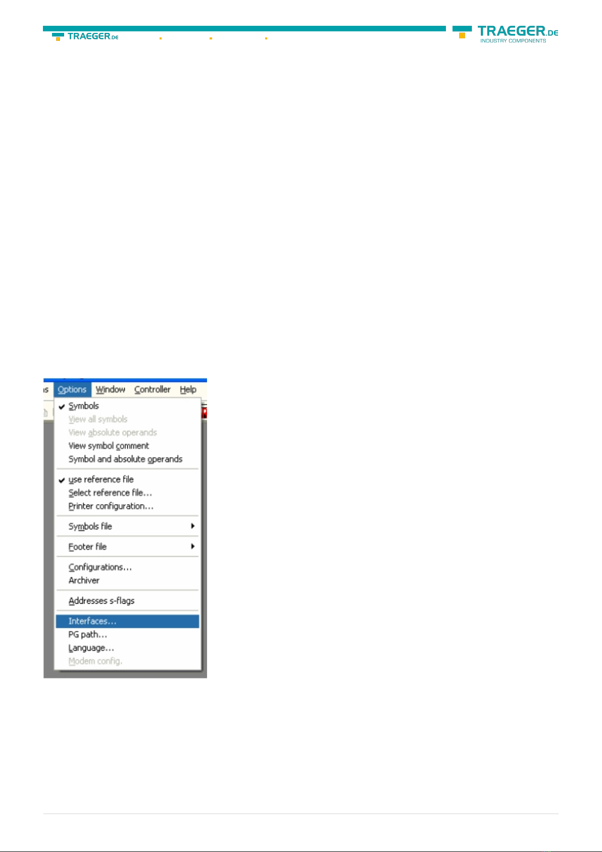
1. Start the PG 2000 software by using the desktop link or by using the application entry in the start menu.
2. Choose from “View” ⇒ “S7-300/400” In the menu “Options“ click “Interfaces“..

MPI-USB user manual 20 / 93 2022/01/21 01:28
3. A dialog appears, in which you are able to set the “AG-Interface” (COM-port) in the section “Interfaces”.
4. Configure the baud rate in the section “Bus access“ to “19,2k“. Below change the value for PC - MPI to
“187,5kBaud“.
5. Save your configuration by pressing “OK“.
6. Now the software is ready to establish a connection to the PLC Click the symbol “Open“ and afterwards
press “PLC”. Alternative you can click:
„File“ ⇒ „Open“ ⇒ „PLC“
This manual suits for next models
1
Table of contents
Other Traeger Cables And Connectors manuals


Popular Cables And Connectors manuals by other brands


Onset Computer Corporation
Onset Computer Corporation T-VER-8051-300 instructions

Simon
Simon 20000091-09 Series manual

Festo
Festo NEBM-S1G9-E Series Assembly instructions

Eaton
Eaton COOPER POWER SERIES installation instructions

iWire
iWire DCCD Plug and Play Harness Kit install guide

Altimium
Altimium SP24H2-4K user manual


