Traeger S7-USB User manual

S7-USB user manual 1 / 85 2019/10/05 05:07
S7-USB user manual
Art.Nr. 9352-S7-USB
documentation of version XXX
1 Description
The MPI-USB cable connects the computer via USB with a MPI interface (9 pin interface of the PLC).
2 System requirements
2.1 Operating system (s)
Windows 98 + SE Windows ME/NT/2000 Windows XP Windows Vista Windows 7
2.2 Software
PLC - programming software (eg PG2000, Step © 7, S7 for Windows, Microwin) Direct driver for Simatic-
Manager for USB PLC - VCOM Software A video description of the installation of direct-driver and how to
configure it can be found on the page support!
2.3 Hardware
USB 1.1 - Type A
2.4 Provided PLCs
S7-200 S7-300 (provides baudrates up to 12M (when the PLC is able to support this) S7-400 (provides
baudrates up to 12M) FM-devices Sinamix (Step7-direct-driver up V1.20 or PLCVCom up V2.71)
MicroMaster and other electrical drives and inverter-feds (Step7-direct-driver up V1.20 or PLCVCom up

S7-USB user manual 2 / 85 2019/10/05 05:07
V2.71) Sinumerik (only PLC-side) SEW-EURODRIVE power inverter and at last routing of S7-PLCs
3 Connecting options
S7-USB directly connected to the PC.
S7-USB is connected to the PC via a USB hub.
S7-USB Connection options with control terminal
4 Installation
4.1 Hardware
The S7/MPI-USB is plugged directly into the PLC. Via the USB cable of the module can be connected to the
PLC as follows:
Normal installation (for programming)
The MPI cable will be connected to the S7 PLC via the 9 pin connector (short side of the cable). The USB
connector on the long side of the cable will be connected with the computer.
S7/MPI-USB as HMI (Human Machine Interface) – adapter
The HMI – function provides the possibility to connect a operator panel (which has instead of a MPI
interface a USB device and understands the HMI protocol) with a S7 PLC (300/400). Connect the cable
between the terminal and the PLC. The HMI – protocol must be part of the operator panel.
There must be a serial communication with the operator panel if this op is new/used at the first time.
Therefore connect your operator panel with the serial COM interface of your computer. After the
communication has been running successfully the panel is ready to be connected to the PLC.
4.2 Software
To communicate with the PLC, please install following products for MPI-USB, S7-USB, MPI-II[only USB], MPI-
LAN and S7-LAN:
Product Driver
TIA-Portal TIC ⇒ “TIC ETH/USB” for MPI, PPI or PROFIBUS
configuration of driver with control-panel ⇒ setting PD/PC-interface
Simatic-Manager TIC ⇒ “TIC ETH/USB” for MPI, PPI or PROFIBUS
Starter-Software TIC ⇒ “TIC ETH/USB” for MPI or PROFIBUS
MicroWin TIC ⇒ “TIC ETH/USB” for PPI and S7-22x-PLC
MicroWin PLCVCom for S7-21x-PLC (no MultiMaster-protocol)
PG-2000 PLCVCom or for S7-LAN/MPI-LAN direct in interface-settings
S7 for Windows TIC ⇒ “TIC ETH/USB” for MPI or PROFIBUS over PD/PC-interface
S7 for Windows PLCVCom
To communicate with the PLC, please install following products for MPI/PPI and MPI-II[only serial]:
Product Driver
TIA-Portal no support because Siemens has taken out the serial support in the driver “PC-Adapter”

S7-USB user manual 3 / 85 2019/10/05 05:07
Product Driver
Simatic-Manager included driver “PC-Adapter” for MPI and PROFIBUS
Starter-Software included driver “PC-Adapter” for MPI and PROFIBUS
MicroWin included driver “PC/PPI-cable”
PG-2000 Standard-function, configuration in the interface-settings
S7 for Windows Standard-function, configuration in the interface-settings
4.3 USB-driver-installation for 32-bit-systems
The S7-Interface S7-USB, MPI-USB or MPI-II-Cabel over USB as well as the devices of TeleService-family will
be connected to USB 1.1-compatible port of the PC.
This opens the Hardware-Installation-Wizard:
We don´t need a connection to Windows update.
Select now “Install from a list or specific location”:


S7-USB user manual 6 / 85 2019/10/05 05:07
Upon a successful installation the “PI_Usb.Sys driver” will be displayed without any warnings in the device
manager:
Will this entry in the device manager shown with a “yellow exclamation mark”, then please install the
driver again or look in the driver properties about the reason.
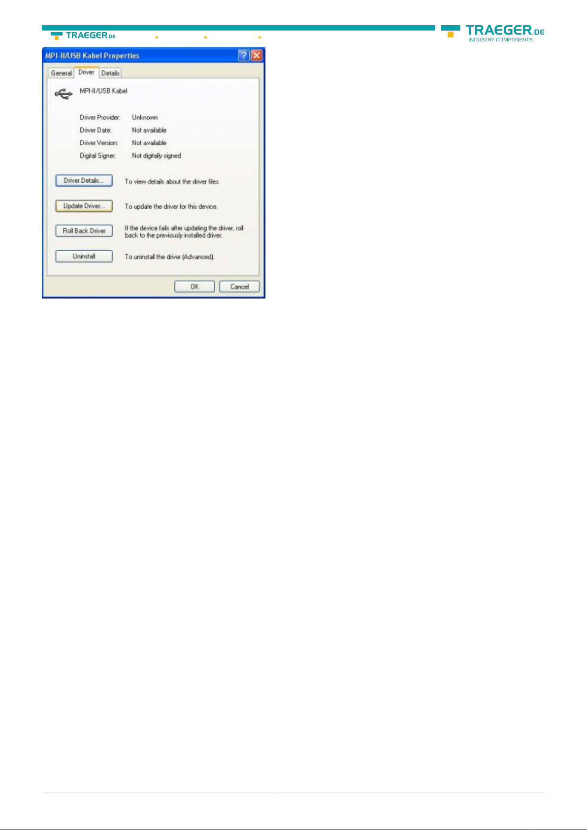
If the driver has to be updated, please use the function “Update …” in the driver properties:
S7-USB user manual 7 / 85 2019/10/05 05:07
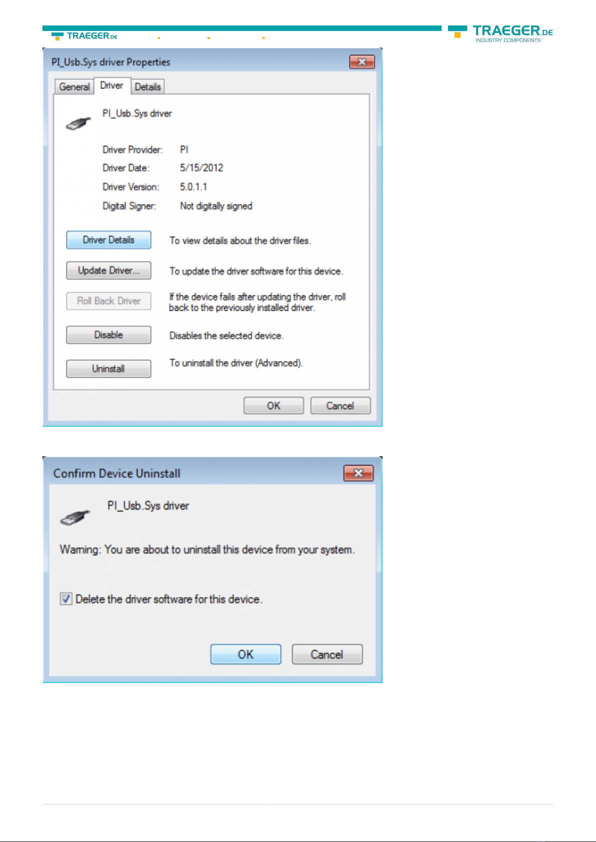
If the driver has to be deleted, please use the function “Uninstall” in the driver properties:
If you install older versions of PLCVCom, Step7-direct-driver or S7IFC, the actual usb-driver will be possible
overwritten by previous versions because it was included until 01/11/2012 in their install-shields!
4.4 USB-driver-installation for Win7 64-bit
The S7-Interface S7-USB, MPI-USB or MPI-II-Cabel over USB as well as the devices of TeleService-family will
be connected to USB 1.1-compatible port of the PC.
After the first plug of the device Win7 displays the message „Installing device driver software“ and after
some time „Device driver software was not installed“. This messages could be closed.
Please start the windows device manager in the control panel.


S7-USB user manual 10 / 85 2019/10/05 05:07
Please select “Browse my computer for driver software” and define as source the folder “..\USB-Treiber-
x64”. Either in the folder where the downloaded drivers were extracted or the directory on the product CD:
After pressing “Next” the message appears of windows UAC


S7-USB user manual 13 / 85 2019/10/05 05:07
If the driver has to be deleted, please use the function “Uninstall” and set the check-box in “Delete the
driver software for this device”:
If you install older versions of PLCVCom, Step7-direct-driver or S7IFC, the actual usb-driver will be possible
overwritten by previous versions because it was included until 01/11/2012 in their install-shields!
S7-USB user manual 14 / 85 2019/10/05 05:07
5 Control elements
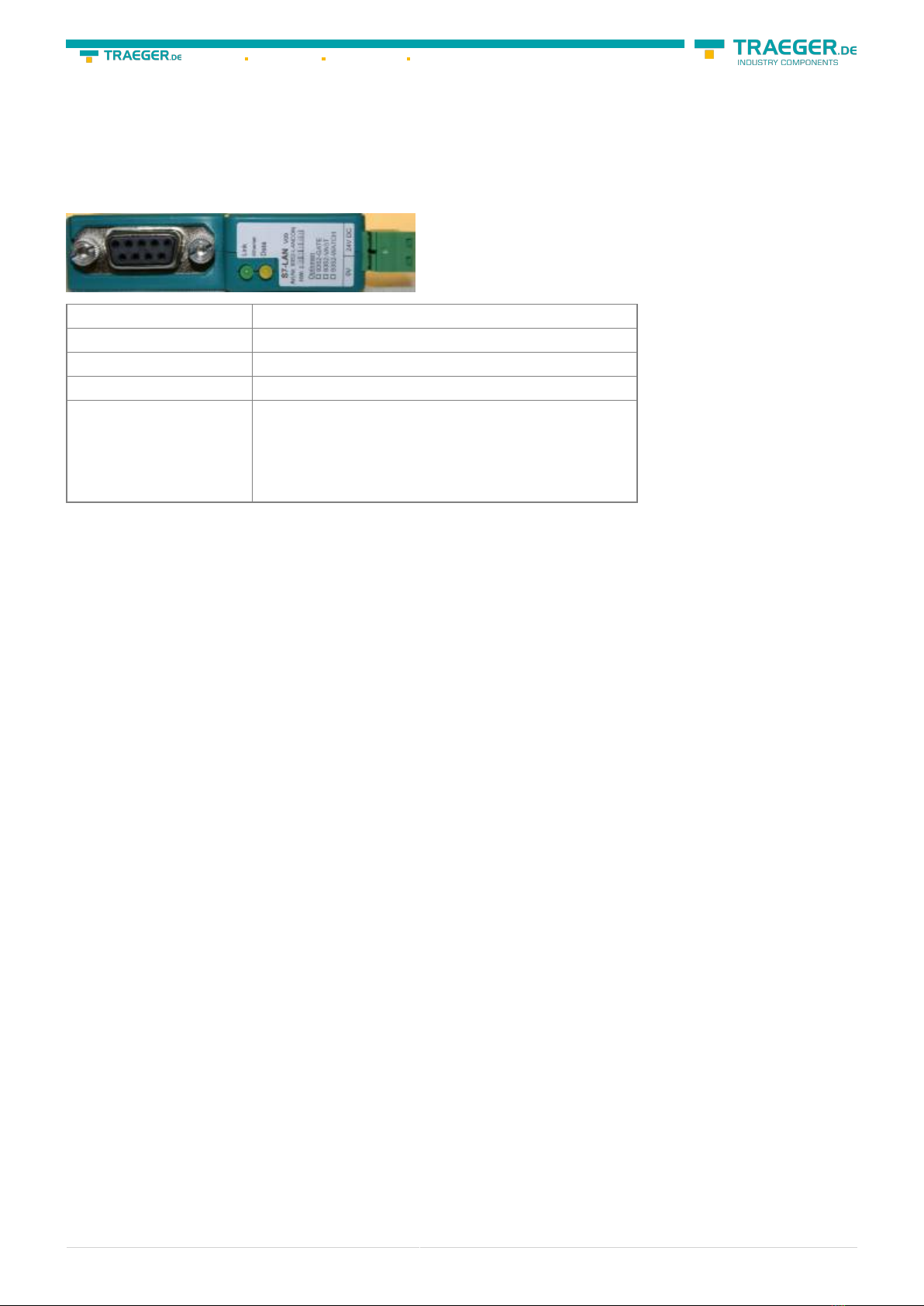
5.1 Lateral LEDs
Green LED OFF Power OFF (S7-USB is not supplied with voltage)
Green LED is blinking BUS Communication
Green LED is on Power ON (S7-USB is supplied with voltage)
Yellow LED is OFF no error in the communication
Yellow LED is blinking
1x Module does not come into bus
2x Participants provided with the same MPI address
3x Wrong MPI baud rate is used
4x Detected parity error on the bus
5x Buffer overflow condition in module
6 Implementing
Connect your module as described in the chapter “ Hardware installation ” to the PLC and to the
programming device or to your computer.
If you want to respond to a PLC via the module you have to comply the requirements as described in the
chapter “system requirements” . In addition,please make sure that the module is properly connected
6.1 Using the PLC-VCOM
(The PLC-VCOM is only needed if your module is not connected via the 9 pin COM port to the computer. For
products with USB, Ethernet connection, etc., the PLC-VCOM is required)
1. Start the PLC - VCOM application (If it has not already started yet).
2. Click in the main window of the PLC-VCOM, in the status area “configure”. The configuration wizard will
start.
3. It lists all the found modules / cables and the additional information’s such as IP address and MAC
address of the module.
4. Choose the desired MPI cable and click „OK“ to go on.
5. If the connection is established the chosen cable is shown in the section state and on the left side you
can see the status connected.
6. It also displays, the PLC-VCOM the IP address for the module and the IP address of the computer which
is connected to the module.
If you have any problems with the use of PLC-VCOM software, go to the chapter PLC – VCOM and look there
for operating instructions.

S7-USB user manual 15 / 85 2019/10/05 05:07
6.2 Programming software to use with direct
access
After you have adjusted and connected the PLC-VCOM or the programming adapter to the COM-port on
your computer, you will be able to connect with your programming software
to the PLC and work with it.
How you have to adjust your programming software is described in the following points:
6.2.1 PG2000 für S7 (V5.10)
1. Start the PG 2000 software by using the desktop link or by using the application entry in the start menu.
2. Choose from “View” ⇒ “S7-300/400” In the menu “Options“ click “Interfaces“..
S7-USB user manual 16 / 85 2019/10/05 05:07
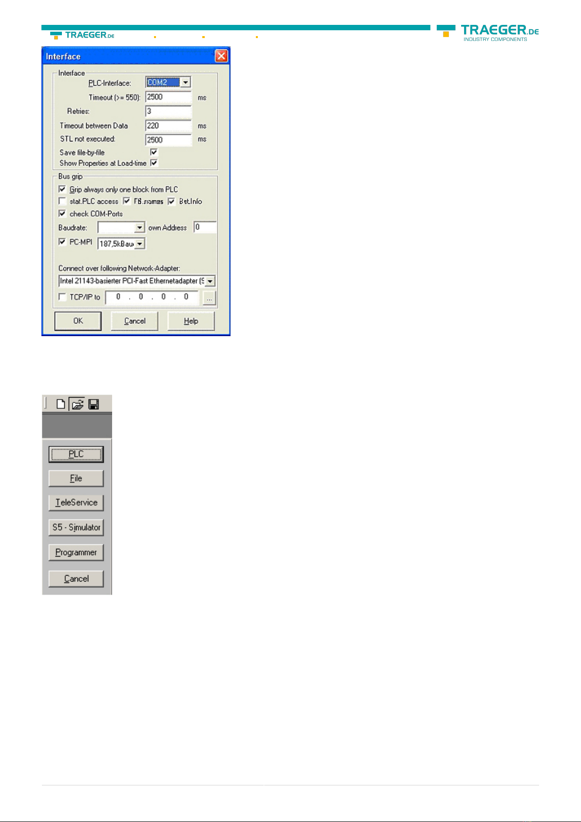
3. A dialog appears, in which you are able to set the “AG-Interface” (COM-port) in the section “Interfaces”.
4. Configure the baud rate in the section “Bus access“ to “19,2k“. Below change the value for PC - MPI to
“187,5kBaud“.
5. Save your configuration by pressing “OK“.
6. Now the software is ready to establish a connection to the PLC Click the symbol “Open“ and afterwards
press “PLC”. Alternative you can click:
„File“ ⇒ „Open“ ⇒ „PLC“

S7-USB user manual 17 / 85 2019/10/05 05:07
The connection between PG 2000 and the PLC is now established. A new window appears. Now you can
edit the blocks in the PLC.
6.2.2 PSet PG/PC interface
This step is required for the following software:
⇒ SIMATIC Step© 7 Manager (v5.2 + SP1)
⇒ Windows Control Center (WinCC) (v6.0)
⇒ Windows Control Center flexible 2004 (WinCC flexible) (v5.2.0.0)
⇒ ProTool/Pro (v6.0 + SP2)
⇒ Microwin 3.2
1. Open the system configuration by using the start menu. 2. Click on „Set PG/PC interface“.
S7-USB user manual 18 / 85 2019/10/05 05:07
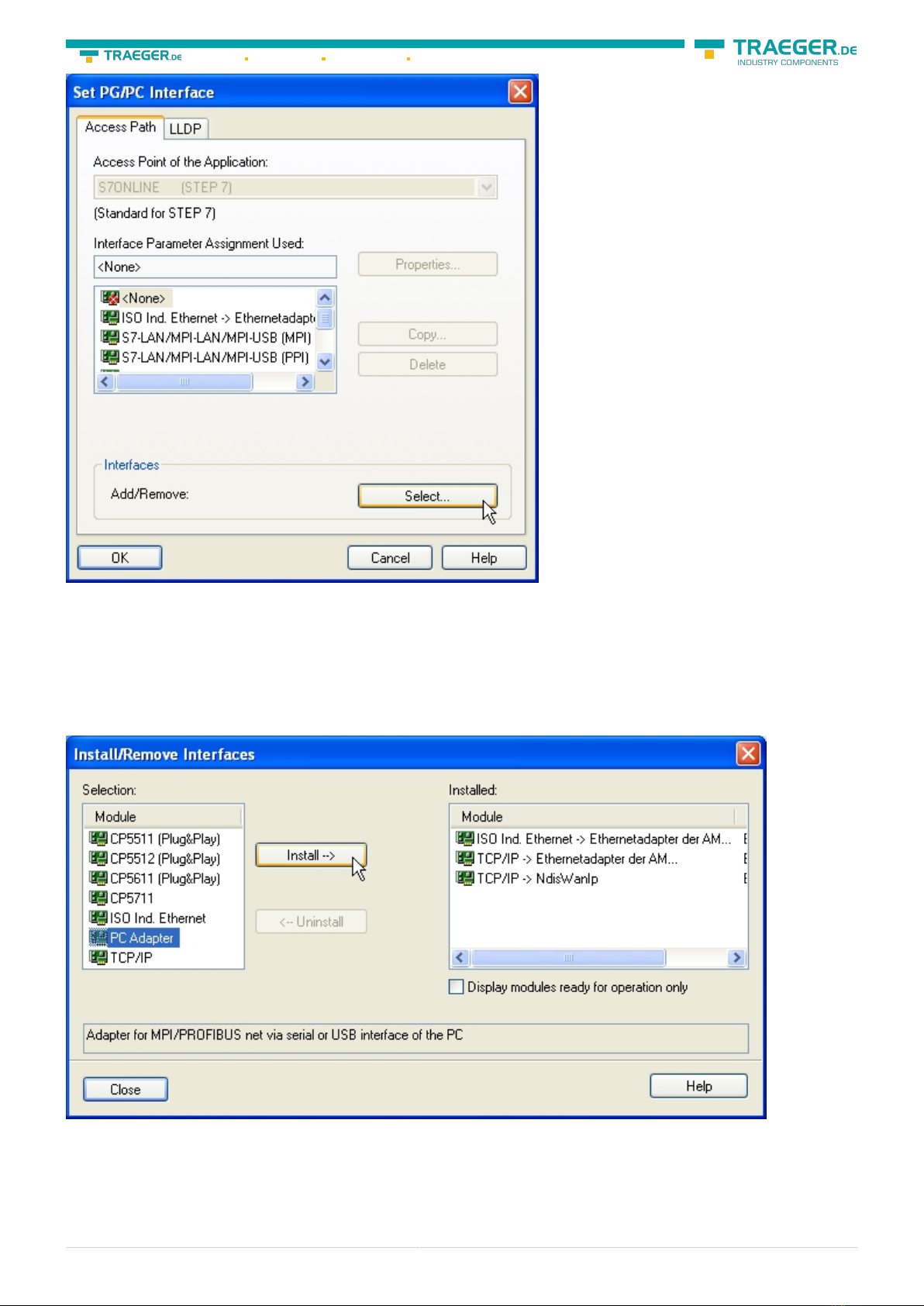
3. A Dialog with a list box named “Interface Parameter Assignment Used:” appears. This box should offer
some “PC - Adapter” entries If this is the case, please continue with the step MPI settings or Profibus
settings. If you can't find these entries go ahead with step PC-Adapter orTCP/IP installation.
6.2.2.1 PC-Adapter(Auto, MPI, PROFIBUS)
4. Click on „Choose“ to add these entries to the PG/PC interface configuration
\
5. In this dialog you can deinstall every installed construction set Furthermore you can add various
modules (see “Selection”) Choose „PC - Adapter“ from the „Selection“ box on the left side and click on
„Install“.
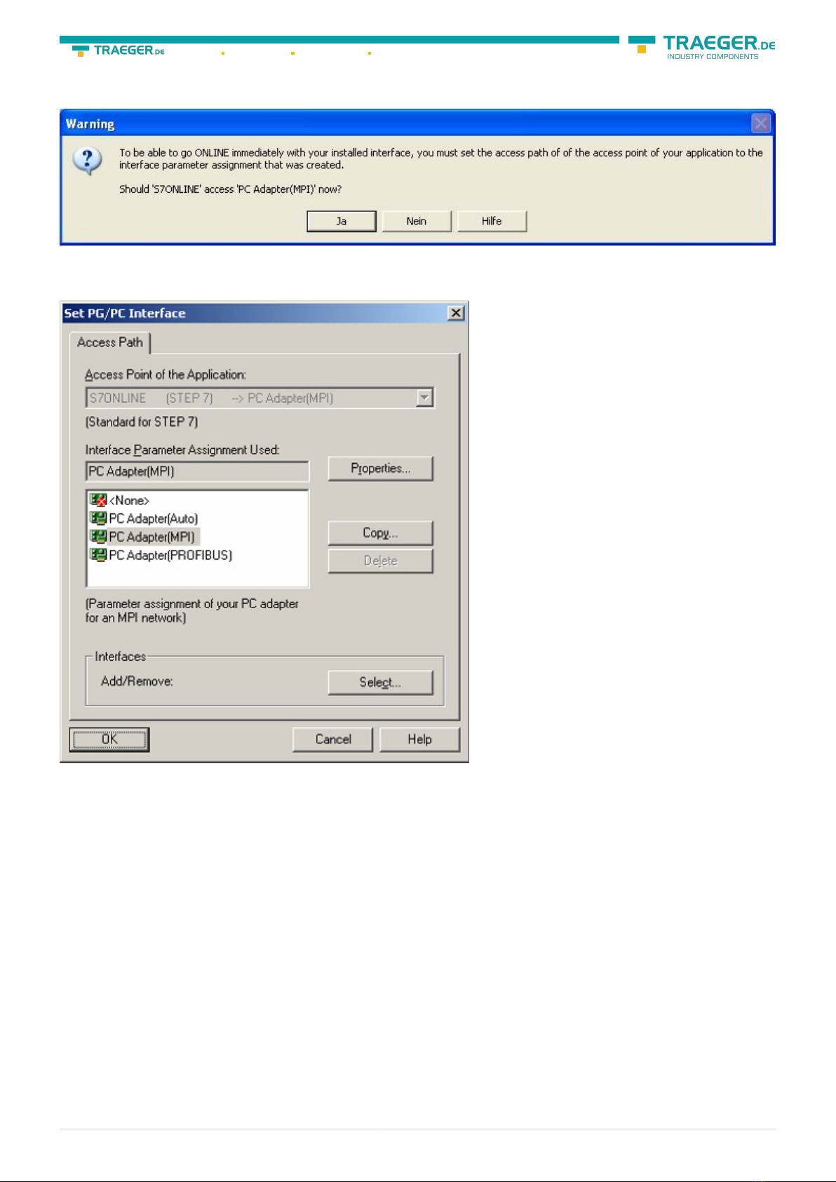
6. The chosen construction set will be installed and a question appears which asks you to use the “MPI“
S7-USB user manual 19 / 85 2019/10/05 05:07
access for the PLC used. Click “Yes“ if you want to use the „MPI“communication type. Otherwise click
“No“(e.g. if you want to use the “PROFIBUS“ communication type).
6.2.2.2 TCP/IP RFC1006 Communication
7. Press “Select” to add the RFC1006 required elements to the PG / PC - interface configuration.
8. In the dialog “Select”, choose“ TCP / IP” and click on “Install”.
9. After successful installation, click “Close”.
10. Back to the “Set PG/PC interface“ dialog you will now find the desired entries called “PC -
Adapter(Auto)“ (not supported), “PC - Adapter(MPI)“ and “PC - Adapter(PROFIBUS)“. Now you are able to
configure the bus. If you want to use the “MPI“communication type go ahead with step MPI setting . The
settings for “PROFIBUS” is explained in Profibus setting .
6.2.2.3 MPI setting

Table of contents
Other Traeger Cables And Connectors manuals


