Traffic Logix SAFEPACE EVOLUTION 15SD User manual

TRAFFIC LOGIX®
SAFEPACE® EVOLUTION 15SD INSTALLATION MANUAL
Radar Sign Installation
Copyright © 2018 Traffic Logix Corporation All rights reserved.

SafePace® Evolution 15SD Installation Manual
Copyright © 2018 Traffic Logix Corporation. All rights reserved.
This manual may not be copied in whole or in part, nor transferred to any other media or language, without the express
written consent of Traffic Logix Corporation.
This document is supplied as a guide for the SafePace Evolution 15SD product. Reasonable care has been taken in
preparing the information it contains. However, it is possible that this document contains omissions, technical
inaccuracies, or typographical errors. Product specifications are subject to change without notice and should not be
considered commitments by Traffic Logix Corporation. Traffic Logix Corporation does not accept responsibility of any
kind for customers’ losses due to the use of this document.
Trademarks
Traffic Logix® and SafePace® are registered trademarks of Logix ITS Inc. All other product and company names are
trademarks or registered trademarks of their respective owners.
This document may contain confidential and proprietary information of Traffic Logix Corporation and/or other third
parties which is protected by copyright, trade secret and trademark law and may not be provided or otherwise made
available without prior written authorization.
Document created: 12:25 PM on Wednesday, October 17, 2018
Document version: 1.0
Traffic Logix Corporation
3 Harriet Lane
Spring Valley, NY
USA 10977
Tel: 1 (866) 915-6449
Fax: 1 (866) 995-6449
Web: www.trafficlogix.com
Email: info@trafficlogix.com
SafePace® Evolution 15SD Installation Manual p. 2

TABLE OF CONTENTS
Chapter 1 4
Introduction 4
Description 5
About this Manual 6
Documentation Conventions 6
Using Additional Customer Resources 7
Online Customer Area 7
Contacting Technical Support 7
Chapter 2 8
Installing the SafePace EV15SD 8
Selecting a Site for the Sign 9
Choosing a Position for the Sign 10
Mounting SafePace EV15SD Signs 11
Chapter 3 14
Power Options for your Sign 14
Solar Power 15
Mounting the Solar Panel 15
Wiring the Solar Panel to the Sign 16
Battery Power 18
Charging the Batteries 18
Installing Lead Acid Batteries in SafePace Evolution Signs 18
Chapter 4 20
Sign Operation and Maintenance 20
Opening and Closing the Sign 21
Operating Your Sign 22
Turning the Sign On and Off 22
Replacing Key Components 23
Warranty 24
SafePace® Evolution 15SD Installation Manual p. 3

Chapter 1
INTRODUCTION
SafePace® Evolution 15SD Installation Manual p. 4

Description
Description
The SafePace EV15SD sign is a compact, lightweight, entry-level radar speed sign intended for private
communities or local roads. It has a bright three-digit speed display. It also offers speed-activated digit color
changes to alert speeders as well as a speed-activated "SLOW DOWN" message.
SafePace® Evolution 15SD Installation Manual p. 5

About this Manual
About this Manual
This manual describes the installation of the SafePace EV15SD sign, along with an optional solar panel, to
the side of a pole. This manual also describes the wiring specifications for solar and battery powered
configurations.
Documentation Conventions
This document uses the following formatting conventions:
Format Description
Bold Gray Used in procedures to indicate menu commands, interface controls
and dialog box options.
Italics Used to place emphasis on certain words.
Monospace text Used for code samples and any information that the user enters.
Italicized
monospace text
Used to indicate text that you should replace with your own. For
example: In the Save As text box, enter c:\filename.ext where
filename.ext is the name of the file you want to save.
> Used to indicate a sequence of commands (and sub commands) to be
carried out in the displayed order. For example File > Exit means to
open the File menu then choose the Exit command. This applies to
menus from the main menu bar, context menus that appear when you
right-click on the interface, and tiles in a tiled interface.
NOTE: Notes are used as reminders or to provide information of interest that supplements or
emphasizes important points of the main text.
TIP: Tips are used to suggest alternative methods, workarounds and/or shortcuts that are not essential
but that you may find useful in a given situation.
CAUTION: Cautions are used to advise users of specific actions that could result in a loss of data.
WARNING: Warnings are used to advise users of specific actions that could result in personal physical
injury or damage to equipment.
SafePace® Evolution 15SD Installation Manual p. 6

Using Additional Customer Resources
Using Additional Customer Resources
The following topics give you more information about additional resources available to our customers:
»Online Customer Area below
»Contacting Technical Support below
Online Customer Area
Visit the Online Customer Area at (https://trafficlogix.com/customer-area/) to gain access to a range of
resources including product documentation, software downloads and support videos, that will allow you to
get up to speed with your Traffic Logix product.
NOTE: The Customer Area is password protected so you may need to apply for a password if you
haven't already obtained one.
Software Downloads
Provides convenient access to the latest versions of our software applications and utilities.
Support Videos
Provides access to several videos that can help you get up to speed with your Traffic Logix product.
Product Documentation
Provides access to the most recent versions of our product documentation. If you are unable to access our
online documentation, please contact our Technical Support Department to discuss alternatives.
Contacting Technical Support
If you have questions or comments regarding this document or SafePace Evolution 15SD, please feel free
to contact our technical support center by phone: 1 (866) 915-6449, or by email: support@trafficlogix.com
SafePace® Evolution 15SD Installation Manual p. 7

Chapter 2
INSTALLING THE SAFEPACE EV15SD
There are several methods and hardware options available for the installation of the SafePace EV15SD
sign.
SafePace® Evolution 15SD Installation Manual p. 8

Selecting a Site for the Sign
Selecting a Site for the Sign
The site you select for the sign may vary with the application in which the SafePace EV15SD radar sign is
being used. However, you should generally adhere to the following guidelines:
»Choose a location where the line of sight from the radar sign to the vehicle will be uninterrupted. Give
consideration to how the location may develop with time. The following types of questions should be
considered:
•Will any trees grow directly in the line of vision?
•Is it likely that road traffic signs will be erected in a position that could obstruct the field of view?
•For solar-powered signs, are the solar panels likely to be blocked by any trees or other structures?
»Install the radar sign directly adjacent to the lane of traffic being targeted since an interfering lane of
traffic may cause inaccurate speed readings.
»Mount the radar sign to a stable and firm structure. Avoid structures that are likely to be affected by
wind or rain. We suggest that you use a 4-inch to 5-inch diameter circular metallic pole, ideally, or a 4-
inch × 4-inch wooden pole. .
SafePace® Evolution 15SD Installation Manual p. 9

Choosing a Position for the Sign
Choosing a Position for the Sign
Similar to other road signs, the SafePace EV15SD radar sign should be installed near the closest lane of
traffic, although off the actual road. The recommended height of the lower edge of the radar speed sign is
approximately 7 feet above the surface of the road. The display should be turned towards oncoming traffic
so that it is clearly visible to approaching drivers.
Figure 1: Example of Sign Location
Figure 2: Zone of Detection
SafePace® Evolution 15SD Installation Manual p. 10

Mounting SafePace EV15SD Signs
Mounting SafePace EV15SD Signs
The SafePace EV15SD sign includes a Pole Banding Mounting system. This is a fairly simple type of
mounting and it requires no special knowledge to easily install the sign.
Installing the Pole Bracket
You can install the Pole Bracket on any type of standard pole with the included banding straps.
TIP: We recommend that you install the bracket on a 3.5-inch or larger pole.
Figure 3: Pole bracket mounted
To install the Pole Bracket using the supplied banding straps:
1. Thread the banding straps through the banding strap holes as shown.
NOTE: The banding straps included are long enough for use with a 5-inch pole. If you want to use a
larger pole, you will need to obtain longer banding straps.
2. Place the bracket against the pole and tighten the straps with a nut driver until secure.
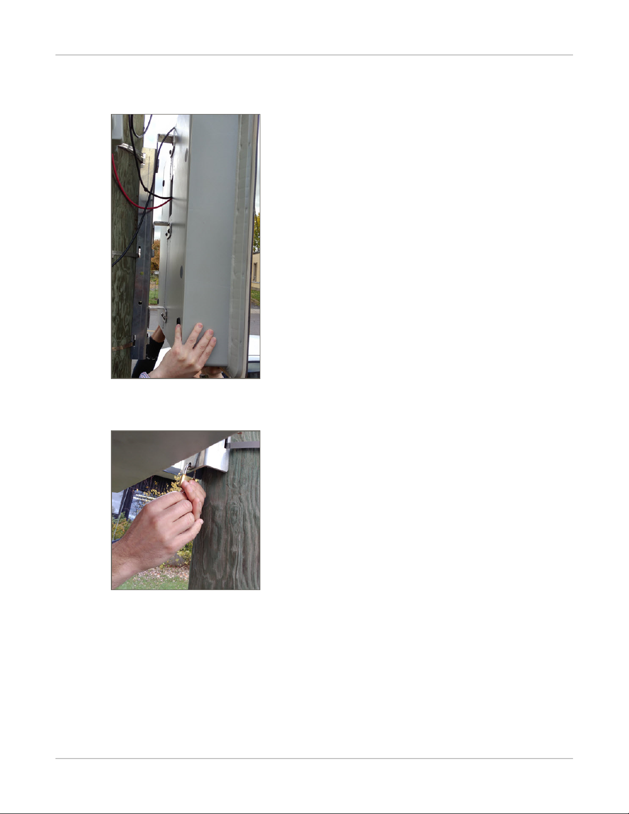
Mounting and Dismounting the Sign
After you install the pole bracket, you can easily mount the SafePace EV15SD sign by sliding it down onto
the Pole Bracket. When the sign is mounted, you should lock it into place.
SafePace® Evolution 15SD Installation Manual p. 11
Mounting SafePace EV15SD Signs
To mount the sign:
1. Align the mounting hooks on the back of the sign with the slots in the bracket.
2. Slide the sign down the bracket.
3. Use the supplied padlock to lock the sign in place.
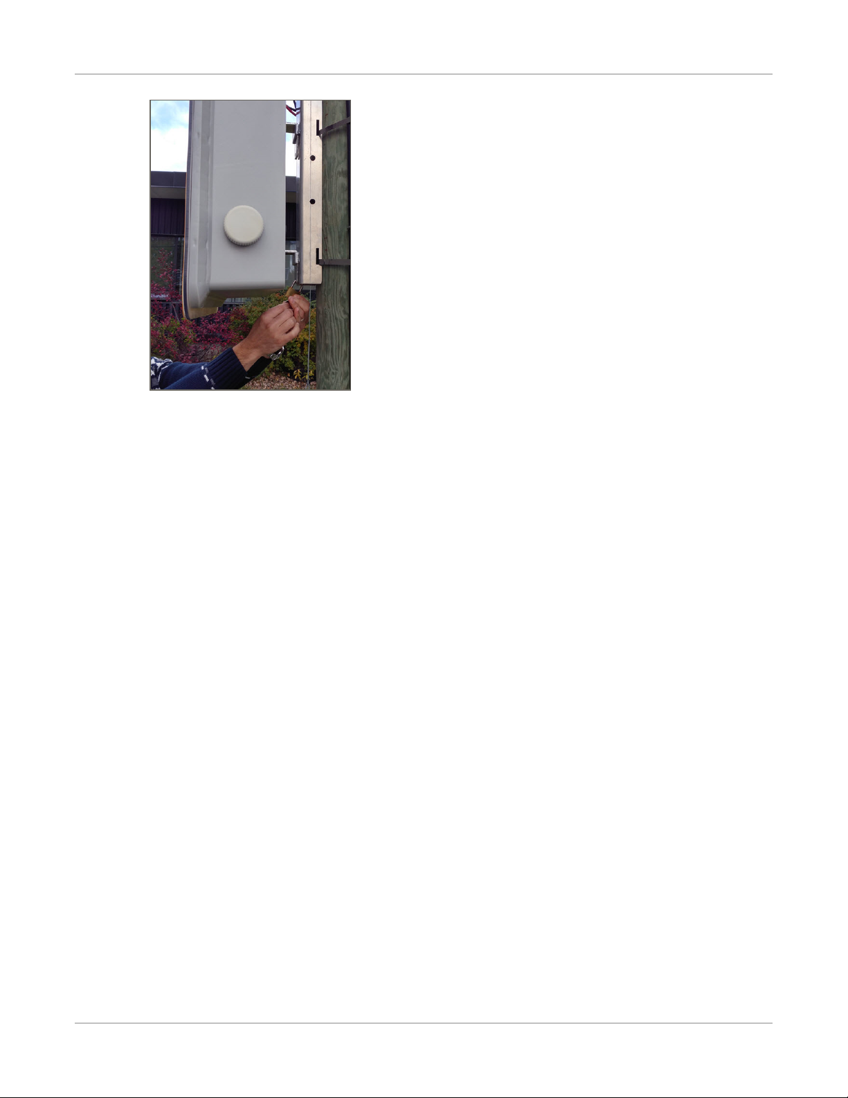
To dismount the sign:
1. Unlock and remove the padlock.
SafePace® Evolution 15SD Installation Manual p. 12
Mounting SafePace EV15SD Signs
2. Slide the sign up and off of the Pole Bracket.
SafePace® Evolution 15SD Installation Manual p. 13

Chapter 3
POWER OPTIONS FOR YOUR SIGN
The SafePace EV15SD sign is offered in several powering models. Depending on what model you have
purchased, powering the sign will vary. The available power options are as follows:
»Solar powered (uses one or more rechargeable batteries for backup)
»Battery powered (includes one or more rechargeable batteries)
NOTE: The warranty on the batteries is limited to 1 year — please contact Technical Support
for more details (see Contacting Technical Support on page 7).
SafePace® Evolution 15SD Installation Manual p. 14
Solar Power
Solar Power
The Solar powered model of the SafePace EV15SD sign includes a solar panel and mounting bracket, one or
more rechargeable batteries, and a solar charger. The solar panel powers the sign when exposed to sunlight
while at the same time charging the batteries to provide a power backup for night-time and cloudy day use.
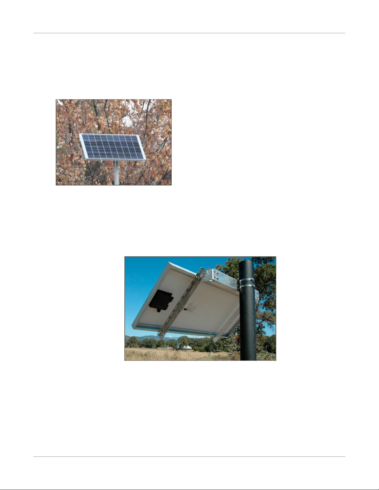
The solar panel is quick to install and should suffice in most installations.
Figure 4: Solar panel
Mounting the Solar Panel
You need to mount the solar panel at the highest point on the pole, optimally 10-12 feet high. Use the
supplied solar panel bracket (see Figure 5: below) and follow the instructions provided by the manufacturer
(included in the bracket’s packaging).
Figure 5: Solar panel mounting bracket
The two-part bracket allows for full adjustment in order to best position the panel towards the sun. It is
optimal to position your solar panel towards due Solar South (not magnetic South), if you are in the
northern hemisphere and towards due Solar North (not magnetic North) if you are in the southern
hemisphere.
Regardless of whether you are in the northern or southern hemisphere, Solar North/South is the position of
the sun in the sky at exactly the midpoint between sunrise and sunset.
SafePace® Evolution 15SD Installation Manual p. 15

Wiring the Solar Panel to the Sign
The solar panel should be angled 15 degrees above the latitude of
the installation site. For example, if the latitude of the installation
site is 45 degrees then the solar panel should be installed at an
angle of 60 degrees, as shown.
You can easily obtain the latitude of the installation site from
mapping software or for free by doing an internet search for
"latitude your_city" where your_city is the name of the city or
region where the panel is being installed.
Wiring the Solar Panel to the Sign
As shown in the following images, the solar panel and the sign come pre-wired with connectors that allow
for a simple installation. The red (male) and black (female) connectors from the sign need to be connected to
corresponding connectors on the solar panel.
Figure 6: Solar panel wires and connectors on the back of the solar panel
Figure 7: Wires and connectors from the sign enclosure.
WARNING: To prevent damage to the solar charger, connect the battery connectors before connecting
the Solar Panel to the sign.
SafePace® Evolution 15SD Installation Manual p. 16

Wiring the Solar Panel to the Sign
To wire the solar panel to the sign:
1. Open the sign and make sure that any battery connectors are properly connected and the sign is
powered on.
2. Close the sign.
WARNING: It is vitally important, whenever you close the sign, that you close and lock all of the latches
properly to avoid water infiltration as this could damage the sign and void your warranty.
3. Insert the connectors from the sign into the corresponding connectors from the solar panel as shown
below.
4. Slide the connectors together until you hear a click and you can no longer slide them apart easily. Once
connected the cables should look like the following:
SafePace® Evolution 15SD Installation Manual p. 17
Battery Power
Battery Power
Battery powered signs come with one or more rechargeable batteries. Depending on your preferences
these batteries will be either lithium or lead acid. Though they are shipped with the sign, typically, the
batteries are not installed in the sign. When you receive the sign, you need to remove the batteries from
their packaging and install them in the sign.
Charging the Batteries
We strongly recommend that you charge the batteries fully before the initial use. The supplied battery
charger is equipped with a charge indicator which shows when the battery is fully charged and ready for use.
To charge the batteries:
1. Connect the charger to the battery.
2. Plug the charger into the wall.
When the charger indicates that the battery is fully charged, the battery is ready for use.
3. Unplug the charger from the wall before you disconnect the battery.
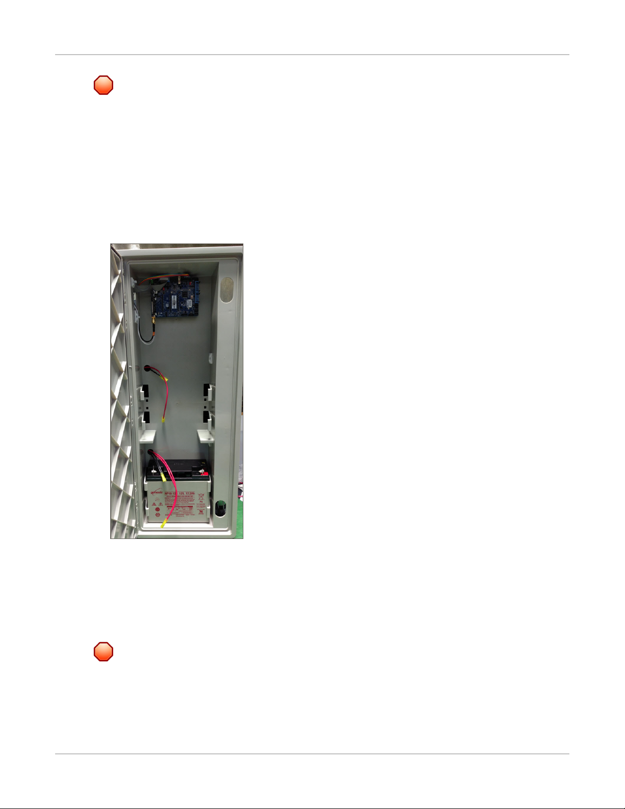
Installing Lead Acid Batteries in SafePace Evolution Signs
Your SafePace EV15SD holds up to four rechargeable lead-acid batteries. Each battery should be placed
with care into a battery bracket inside the sign.
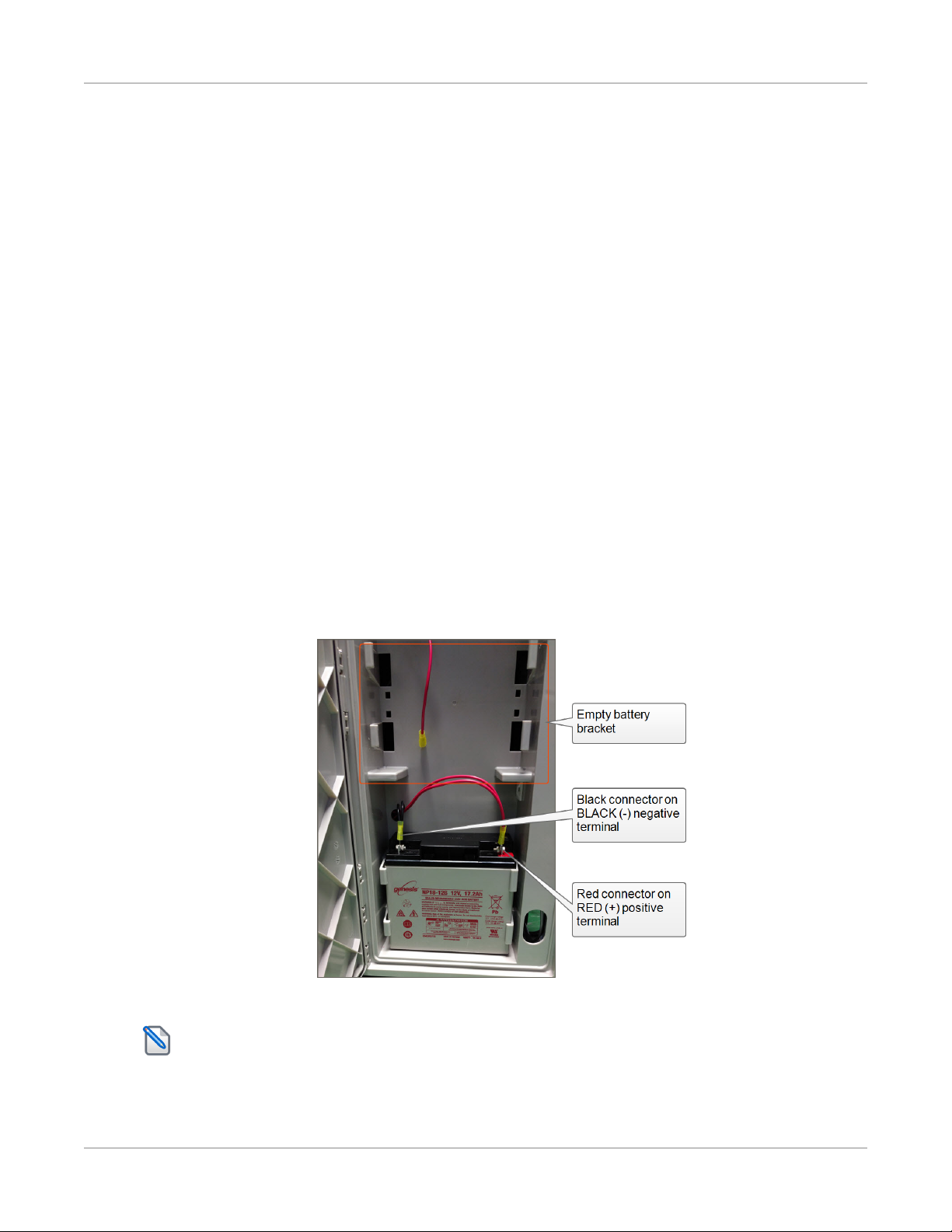
Figure 8: Lead acid battery inserted and connected
NOTE: This image is for illustrative purposes only and the number of batteries in your sign may be
different from that shown.
SafePace® Evolution 15SD Installation Manual p. 18
Installing Lead Acid Batteries in SafePace Evolution Signs
WARNING: Proper battery care and maintenance is required. Improper care and maintenance of
batteries may void the product warranty. We strongly recommend that you do the following:
• Replace the batteries every TWO years, in order to prevent damage to the sign.
• Remove the batteries whenever you need to transport the sign, in order to prevent internal damage to the
sign.
To install the battery in the battery bracket:
1. Make sure that the battery has been removed from its packaging, then open the sign enclosure.
2. Carefully slide the battery into the bracket and make sure that it is properly seated as shown in the
following image.
3. When the battery is secured in the battery bracket, slide the battery connectors onto the battery
terminals as follows:
•Slide the black connector onto the BLACK (-) negative terminal.
•Slide the red connector onto the RED (+) positive terminal.
4. When you are finished, you can close and latch the sign enclosure.
WARNING: It is vitally important, whenever you close the sign, that you close and lock all of the latches
properly to avoid water infiltration as this could damage the sign and void your warranty.
SafePace® Evolution 15SD Installation Manual p. 19

Chapter 4
SIGN OPERATION AND MAINTENANCE
SafePace® Evolution 15SD Installation Manual p. 20
Table of contents
Other Traffic Logix Lighting Equipment manuals

Popular Lighting Equipment manuals by other brands


OVE
OVE S14 II 24ft installation manual

THORPE
THORPE Philip Payne 1880 Installation leaflet

Clevetronics
Clevetronics CleverEVAC CLP Cleverfit Pro Dynamic Green ASSEMBLY, INSTALLATION & MAINTENANCE INSTRUCTIONS

ACME
ACME BW-54-10FC II RL user manual

Brighter
Brighter Magic Matrix user manual

Govee
Govee H7050 user manual