Clevetronics CleverEVAC CLP Cleverfit Pro Dynamic Green User manual

1949393
V1.0
1 December 2021
UK Instruction Sheet Template – V1.1 – Updated: 20/11/2020
Note:
This luminaire (with reinforced insulation between control/LED terminal and AC supply) contains non-user
replaceable light source and battery - to be replaced (if required, refer installation instructions for battery
replacement) by Clevertronics service personnel/agents or a registered electrician.
Battery Replacement:
1. Prior to any work, isolate the power to the luminaire that requires battery replacement.
2. Disengage the slide connect bracket from the exit body.
3. Remove Cover Plate.
4. Remove cable tie holding the battery and remove the Battery Connector from the Emergency
Driver.
5. Replace battery, connect to Emergency Driver and secure with cable tie.
6. Replace Cover Plate and reinstall the fitting.
Testing Procedure:
When the unit is connected to the un-switched active, it must be allowed to charge the battery for at
least 24 hours. The emergency lamp only illuminates during a power fail. Conduct the following tests:
•The emergency lamp must illuminate for at least 180 min after disconnection from the mains. If the
unit fails to illuminate for the requisite time, remedial action must be taken to repair the situation
and once completed, the unit must pass a subsequent test.
•Press and hold Test Button*, the product will go into Dynamic Green mode.
NOTE: Initiating a Function or Duration test using the Zoneworks Software will trigger Dynamic Green for
completion of the test.
*The Test button needs to be held for longer than 1 seconds for the product to go into Emergency Mode.
Trouble Shooting:
Below are a list of common problems and their possible causes.
Fault: The Green LED Test Switch indicator is not illuminated.
Check: A.C. is connected and is turned on.
Battery is connected
Test Switch for damage.
Fault: Lamp does not illuminate in emergency mode.
Check: A.C. is connected.
Lamp is correctly inserted.
Battery is connected
Fault: Lamp illuminates in emergency mode, but only stays on for a short period.
Check: Battery has been allowed to charge for at least 24 hours.
Battery for damage.
Fault: The Dynamic Green is not sequencing.
Check: The 24 Volt/VF control is connected and turned on.
Polarity of 24V control.
Check that the correct interface control is selected.
Warranty:
For Product Warranty information and Terms and Conditions of Sales please refer to our website
https://clevertronics.co.uk/product-warranty-statement/
CLP™ Cleverfit Pro Dynamic Green
Installation & Maintenance Instruction Leaflet
Australia (Head Office)
Website: www.clevertronics.com.au
Email: info@clevertronics.com.au
Phone: +61 3 9559 2700
Fax: +61 3 9559 2799
UK OFFICE
Website: www.clevertronics.co.uk
362 Stockley Close
West Drayton UB7 9BL
Phone: 01895 430 255
Models:
DYGC-xCP-uu-vv-ww-xx-yy-zz
Testing:
Options:
Zoneworks
xx = ZW
Running man with right arrow
yy=RR
Z/W DATA
xx = DATA
Running man with left arrow
yy=RL
Zoneworks HIVE
xx = HVG
Running man with Up arrow
yy=RU
Running man with down arrow
yy=RD
Normally Open
xx=NO
Double sided Running Man Arrow
yy=DS-RAOW
Normally Closed
xx=NC
Dynamic Green Disabled
uu=DDG
Activated Only by Fire Panel
xx=AOFP
Theater Mask
vv=TH
Weatherproof
x=W
SoundEscape module
ww=SND
Black
zz=BLK
Spare Parts:
1550030
BATT: LP 3.2V 3200mAh 300mm lead,noBRKT
8002927
PCA: DYxx Driver Board #CT10142-L9
Important:
It is illegal for anyone, except for a licensed electrician to install or maintain this product. Before installation,
ensure that the electricity supply has been switched off and isolated. Installation must be carried out in
accordance with the relevant British Standards.
Clevertronics Pty Ltd is a vendor of CleverEVAC products. It is not a fire engineer or designer. It does not
purport to recommend its products for use in any particular application or to achieve any particular
outcome. Purchasers and users of its products must take their own steps to ensure compliance with
statutory requirements, safe practice and suitable application of the products.
1949393
V1.0
1 December 2021
UK Instruction Sheet Template – V1.1 – Updated: 20/11/2020
Installation:
The CLP Cleverfit Pro Dynamic Green can be installed either Ceiling or Wall Mounted. The CLP Cleverfit
Pro Dynamic Green uses a “slide connect bracket base” that is mounted and wired into position first. The
main body can be installed once the base is wired or later to avoid damage during the construction phase.
Please follow the steps below to install the CLP Cleverfit Pro Dynamic Green Exit:
•Disengage the slide connect bracket from the exit body. Position the base in the mounting position.
•Using the bracket as a guide, mark 2 holes for mounting and one for mains access. Then install the
bracket using appropriate fixings (not supplied).
•Remove the Terminal Block Cover.
•Route the AC power and 24/VF control cables through the access hole and connect to the terminal
block as shown below.
•Reinstall the terminal block cover.
•Install the exit fitting to the slide bracket.
Dynamic Green 24 Volt (24V)/Volt Free (VF) Operation and Testing
Activation of the Dynamic Green is controlled via 24V/VF control interface. The fitting comes pre-set as
normally OFF. This is switched via an intelligent circuit inside the fitting. This is controlled by the 24V/VF
input from a fire panel or other source. If you would like to change the activation of the Dynamic Green
from Normally OFF to Normally ON change the Dip Switch no.6 on the Main LED Board (found under
the Running Man diffuser) to 0.
NOTE: For the Dip Switch setting to take effect the power and battery will need to be disconnected and
reconnected.
For –SND products this operation is set depending on the part number ordered and cannot be changed
by user.
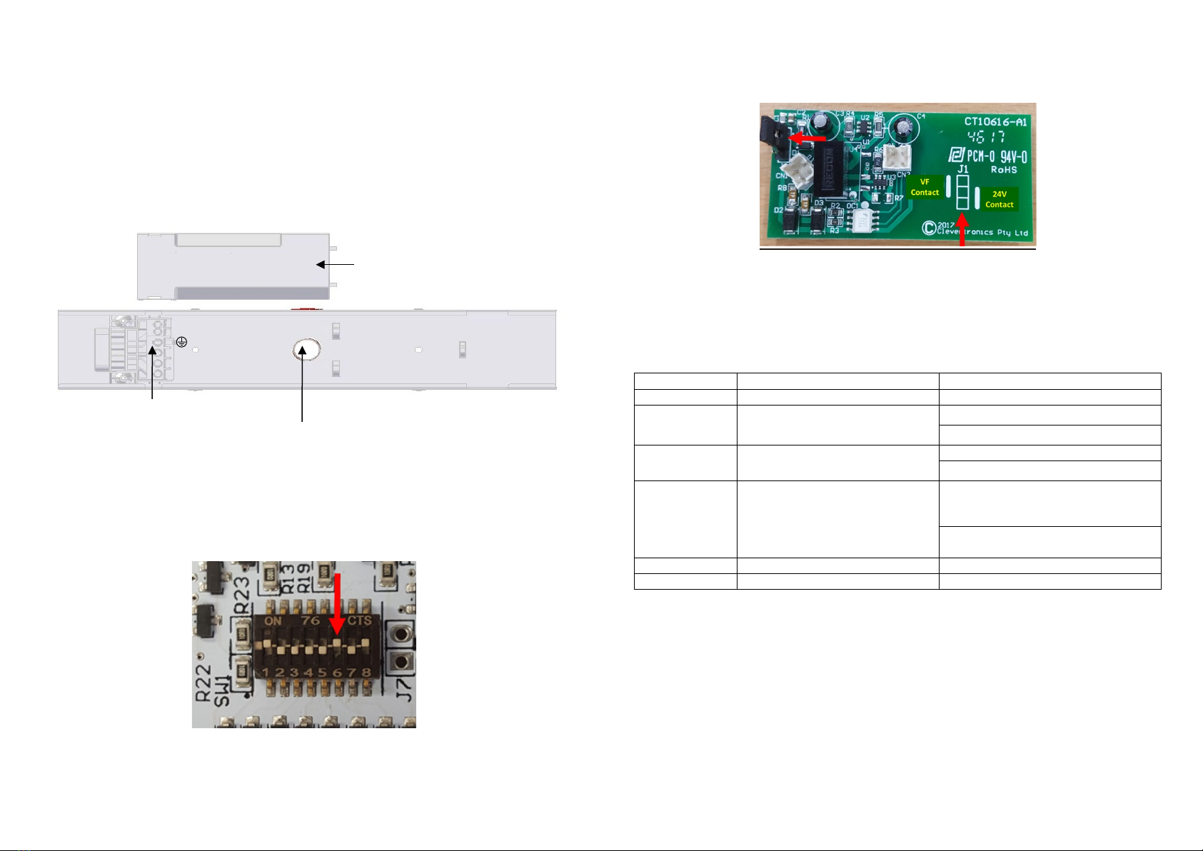
Selecting the Type of the Interface
The fitting comes pre-set to the Volt Free (VF) control interface, to change this to 24V you will have to
change the jumper on J1 from 1-2 (Image below) to 2-3 on the Contact board found next to battery
compartment. Please see image below.
Zoneworks, HIVE and DATA Monitored Options
Fittings with part numbers -ZW, -HVG, -DATA are fitted with Zoneworks communications modules
(nodes). These fittings are monitored using either Powerline Carrier Technology that utilize the power
cable to provide data communication, RF transceiver modules operating in the ISM band or a dedicated
data cable to/from data routers installed on a dedicated data trunk connected to a central Server (can also
be connected via Ethernet/Internet/Fibre). Zoneworks software on the server is used to monitor,
coordinate testing and collate test data from each fitting. Zoneworks Fittings can be commissioned by a
single push of the test switch or by scanning the supplied barcode. The LED Test Switch indicator provides
a multifunction indication of the status of the fitting during testing and normal operation:
Option
State
LED Operation
ZW, HVG, DATA
Commissioned
LED on Solid (Green)
ZW, DATA Un-commissioned Batt plugged-in: yellow 1s, green 1s
Batt unplugged: red 1s, off 1s
HVG Un-commissioned
With network connectivity
Batt plugged-in: yellow 1s, green 1s
Batt unplugged: red 1s, off 1s
HVG Un-commissioned
Without network connectivity
Batt plugged-in: yellow 250mS, green
250mS, yellow 250mS, green 250mS,
green 1s
Batt unplugged: red 250mS, off
250mS, red 250mS,off 250mS, off 1s
ZW, DATA
Emergency Light Test In Progress
LED flashes at yellow 5s , 0ff 1s
HVG
Emergency Light Test In Progress
LED flashes at yellow 1s , 0ff 1s
In the case of the DATA version a 2-way “figure 8” cable and terminal block facilitates the connection to
the DATA network via a multi-drop bus (daisy chain connection). For further information of installation of
a Zoneworks system, please refer to the Zoneworks Users Guide and Commissioning Guide (incl. DATA
version)
Caution:
On many building sites, power circuits may be cut off in an uncontrolled and repetitive basis during
construction. As a result, any Exit & Emergency Units, on these circuits, will have their batteries
discharged or “cycled”. The Li-ion battery in the Exit & Emergency Unit has been selected to give
excellent long life performance in a controlled IEC 60598-2-22 testing environment. Excessive battery
cycling will reduce through-life performance and may lead to premature battery failure. Battery warranty
claims, as a result of such abuse, are specifically EXCLUDED from Clevertronics warranty terms.
Terminal Block Cover
Cable Entry Point – Inside of bracket for ceiling mount, 20mm diameter, located in centre of bracket. Bracket shown
with the terminal block cover removed.
Terminal Block
24 –
24 +
N
L
NC
Other Clevetronics Lighting Equipment manuals

Clevetronics
Clevetronics L10 LUBPRO Series Installation and operating instructions

Clevetronics
Clevetronics L10 LUBPRO-SM-UPS User manual

Clevetronics
Clevetronics L10 LUBPRO UPS Series User manual

Clevetronics
Clevetronics L10 LVELED Series Installation and operating instructions

Clevetronics
Clevetronics LP CBS2LEDS-DIF Series User manual

Clevetronics
Clevetronics L10 LVELED Series User manual


