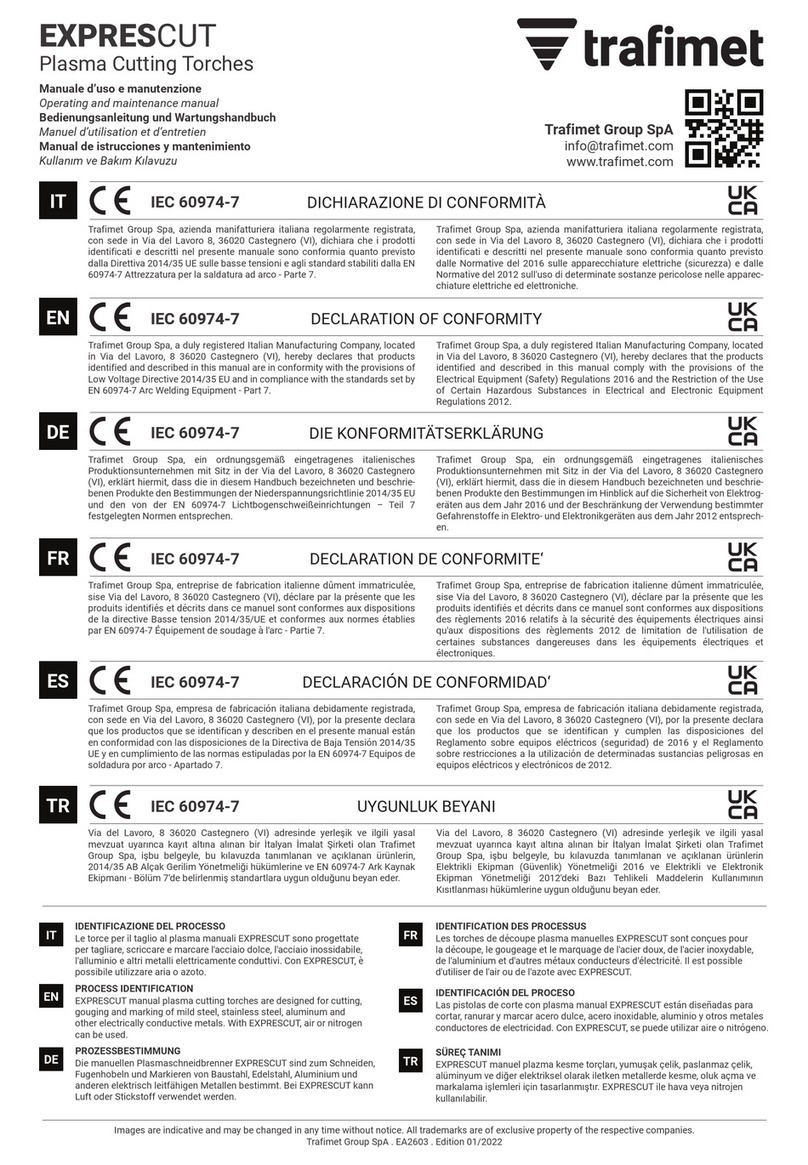
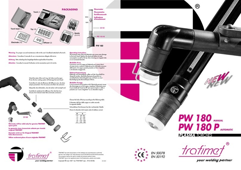
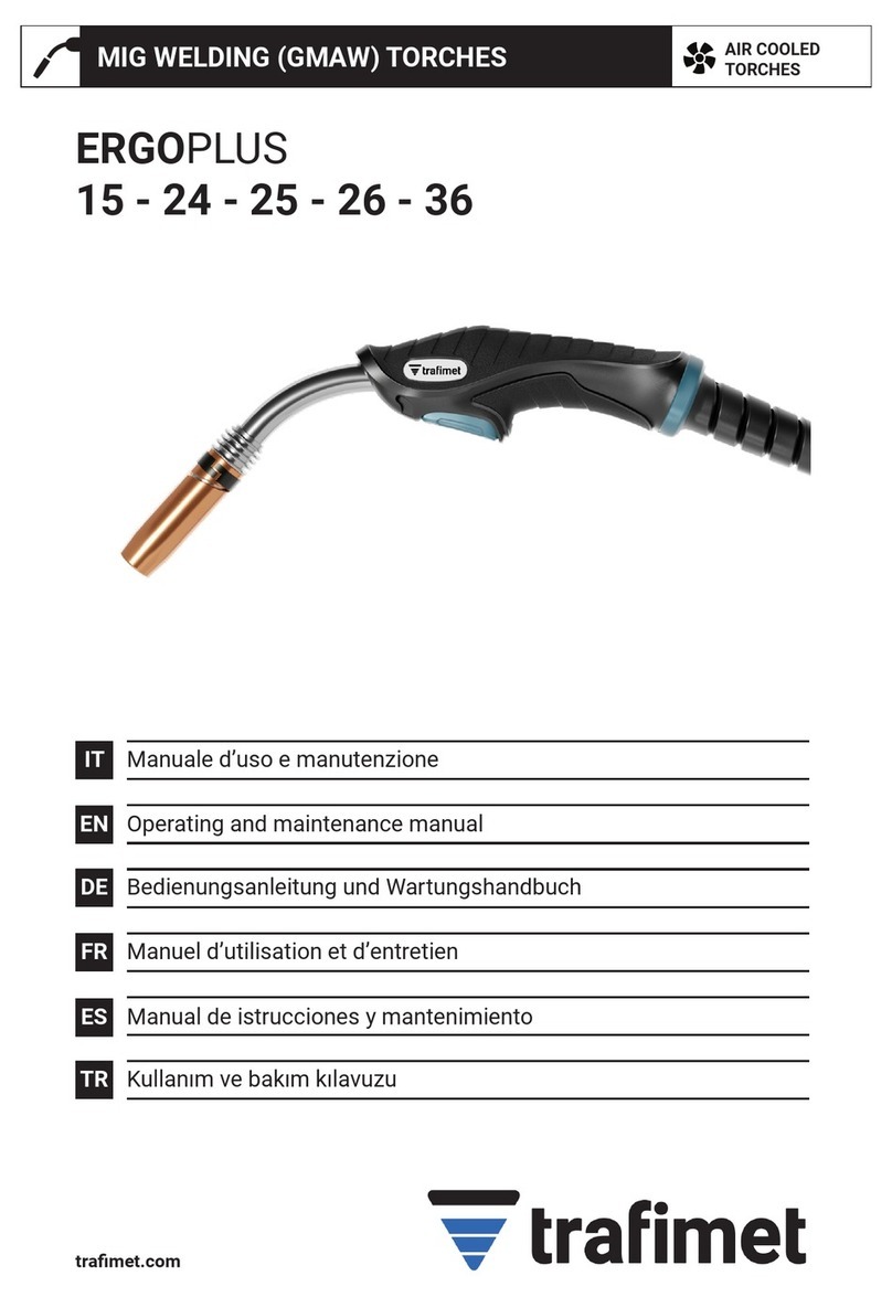
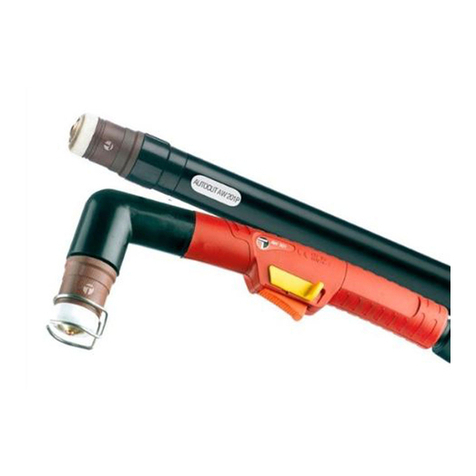
Trafimet PLUSCUT 85 Operating instructions

tramet.com
PLUSCUT
85 - 105
IT
EN
DE
FR
ES
TR
AIR COOLED
TORCHES
PLASMA CUTTING TORCHES
Manuale d’uso e manutenzione
Operating and maintenance manual
Bedienungsanleitung und Wartungshandbuch
Manuel d’utilisation et d’entretien
Manual de istrucciones y mantenimiento
Kullanım ve bakım kılavuzu

±°C
EN 60974-7
Tutti i marchi sono di proprietà dei rispettivi proprietari. Le informazioni e le immagini sono indicative e possono essere soggette a modiche in qualunque momento senza preavviso. © 2022 Tramet Group SpA
DICHIARAZIONE DI CONFORMITÀ
DICHIARAZIONE DI CONFORMITÀ
Tramet Group Spa, azienda manifatturiera italiana regolarmente registrata, con sede in Via del Lavoro 8,
36020 Castegnero (VI), dichiara che i prodotti identicati e descritti nel presente manuale sono conformi
a quanto previsto dalla Direttiva 2014/35 UE sulle basse tensioni e agli standard stabiliti dalla EN 60974-7
Attrezzatura per la saldatura ad arco - Parte 7.
Tramet Group Spa, azienda manifatturiera italiana regolarmente registrata, con sede in Via del Lavoro 8,
36020 Castegnero (VI), dichiara che i prodotti identicati e descritti nel presente manuale sono conformi a
quanto previsto dalle Normative del 2016 sulle apparecchiature elettriche (sicurezza) e dalle Normative del
2012 sull'uso di determinate sostanze pericolose nelle apparecchiature elettriche ed elettroniche.
IDENTIFICAZIONE DEL PROCESSO
Le torce per il taglio al plasma manuali PLUSCUT sono progettate per tagliare, scriccare e marcare l'acciaio dolce, l'acciaio
inossidabile, l'alluminio e altri metalli elettricamente conduttivi. Con PLUSCUT, è possibile utilizzare aria o azoto.
AVVERTENZE
PRECAUZIONI DI SICUREZZA
Indossare guanti e altri
indumenti da lavoro
adeguati in conformità alle
normative locali.
I fumi sono pericolosi per
la salute. Usare sistemi per
l'aspirazione dei fumi oppure
lavorare esclusivamente in
ambienti ventilati.
Proteggere gli utensili
elettrici dalla pioggia.
Non utilizzare la torcia
su superci o pavimenti
bagnati oppure in ambienti
con un'umidità elevata.
I cavi della torcia non
devono essere schiacciati
da oggetti pesanti.
Rivolgere la torcia lontano
da sa stessi e dagli altri.
L'arco è pericoloso per gli
occhi. Indossare un casco
protettivo. Le persone
nelle vicinanze devono
indossare una protezione
per gli occhi.
Non utilizzare la
torcia per tagliare
contenitori di materiali
inammabili, anche
se i contenitori sono
vuoti. Tenere la torcia
lontano da liquidi
Non modicare la torca
né apportare modiche
strutturali ad essa.
Prima di utilizzare le
torce, è necessario
leggere attentamente
il manuale d'uso e
manutenzione.
Condizioni ambientali
Funzionamento:
Da -10 °C a +40 °C (da +14 °F a +104 °F)
Trasporto e stoccaggio:
Da -25 °C a +55 °C (da -13 °F a +131 °F)
Umidità relativa:
Fino al 90% a 20 °C (68 °F)
Spegnere la fonte di
alimentazione prima di
eseguire la manutenzione
della torcia. La sostituzione
delle parti di ricambio o
attività di manutenzione
di altro tipo devono
essere effettuate dopo il
raffreddamento della torcia.
Smaltire questo prodotto
in modo responsabile dopo
l'uso.
Le torce e le parti
usate devono essere
adeguatamente riciclate in
conformità ai requisiti/alle
normative locali.
IT MANUALE D'USO E MANUTENZIONE
L'attivazione e la
manutenzione delle torce
devono essere eseguite
esclusivamente da
personale qualicato.
Per "personale qualicato"
si intendono gli utenti che
lavorano in conformità agli
standard e alle disposizioni
di cui sopra. Questi utenti
devono identicare e
valutare correttamente
i possibili rischi/pericoli
associati all'utilizzo delle
torce per il taglio al plasma.
2

Tutti i marchi sono di proprietà dei rispettivi proprietari. Le informazioni e le immagini sono indicative e possono essere soggette a modiche in qualunque momento senza preavviso. © 2022 Tramet Group SpA
COLLEGAMENTI
UTILIZZO
MANUTENZIONE
Prima di collegare la
torcia, spegnere la fonte
di alimentazione, staccare
la spina e chiudere la
fornitura di gas.
Prima di collegare
la torcia alla fonte
di alimentazione,
vericare che i
collegamenti elettrici
siano corretti e in
conformità agli
schemi elettrici
allegati, laddove
applicabile.
Accertarsi che la
pressione dell'aria e la
portata corrispondano
ai valori specicati per
la torcia.
L'aria compressa deve
essere
priva di sporcizia,
umidità e olio.
Non piegare i cavi e i tubi
essibili per evitare danni
che potrebbero impedire
la corretta circolazione del
gas e del refrigerante.
Non utilizzare la torcia
per scopi diversi dal
taglio al plasma, dalla
scriccatura e dalla
marcatura.
Spegnere la fonte
di alimentazione
prima di eseguire la
manutenzione della
torcia. La sostituzione
delle parti di ricambio o
attività di manutenzione
di altro tipo devono
essere effettuate dopo
il raffreddamento della
torcia.
Sostituire la punta quando
è usurata (ad esempio,
il foro è più grande o la
sua forma è cambiata).
Sostituire l'elettrodo
quando è usurato (ad
esempio, la fossa supera
1,2 mm).
Serrare l'ugello in modo
che le parti siano ssate
saldamente. Accertarsi
che la punta non possa
ruotare facilmente.
Controllare
periodicamente le
condizioni del cavo e del
manico. Le riparazioni
possono essere eseguite
solo da personale
qualicato.
Usare sempre parti di
ricambio e materiali
di consumo originali
Tramet.
3

1
2
3
4
Tutti i marchi sono di proprietà dei rispettivi proprietari. Le informazioni e le immagini sono indicative e possono essere soggette a modiche in qualunque momento senza preavviso. © 2022 Tramet Group SpA
FUNZIONAMENTO
Informazioni importanti per l'utilizzo sicuro della torcia per il taglio al plasma e il funzionamento dei
dispositivi di interblocco e di sicurezza.
Classicazione dei comandi elettrici della torcia: 42 V CC 0,5 A.
Prima di usare la torcia, accertarsi che tutti i cavi siano in buone condizioni e che i connettori siano ssati
correttamente.
L'arco pilota si accende soltanto se i materiali di consumo della torcia sono installati correttamente.
Il pin di sicurezza forma due contatti di sicurezza collegati elettricamente quando il cappuccio di tenuta è
installato correttamente.
Requisiti afnché una fonte di alimentazione per il taglio al plasma formi un'unità sicura con la torcia per il
taglio al plasma:
• Poiché l'ugello per il taglio al plasma (punta) non può essere protetto dal contatto diretto per motivi
tecnici, la fonte di alimentazione per il taglio al plasma deve essere conforme allo standard EN 60974-7.
• La torcia per il taglio al plasma collegata alla fonte di alimentazione per il taglio al plasma o utilizzata con
essa deve essere conforme allo standard EN 60974-10.
• La fonte di alimentazione per il taglio al plasma deve essere conforme anche allo standard EN 60974-1.
• La fonte di alimentazione per il taglio al plasma e la torcia per il taglio al plasma devono avere lo stesso
tipo di accensione (No HF o HF), nonché la stessa corrente nominale e lo stesso ciclo di lavoro richiesto.
Come usare la leva di sicurezza e il grilletto della torcia
Pin di sicurezza
IT MANUALE D'USO E MANUTENZIONE
Leva in posizione di sicurezza.
Posizione di rilascio della leva di sicurezza.
Premere il pulsante per avviare l'accensione
ad arco.
Per interrompere il taglio, rilasciare il grilletto.
4

11
2
3
90˚
90˚
Tutti i marchi sono di proprietà dei rispettivi proprietari. Le informazioni e le immagini sono indicative e possono essere soggette a modiche in qualunque momento senza preavviso. © 2022 Tramet Group SpA
FUNZIONAMENTO
Direzione di taglio al plasma
Il usso di aria/gas al plasma esce dalla torcia in modo vorticoso per garantire la stabilità dell'arco.
A causa del usso vorticoso del gas al plasma, un lato del taglio risultante è più dritto (angolo di smussatura inferiore)
rispetto all'altro.
Nella gura, il lato destro del taglio rispetto alla direzione di taglio è più dritto.
Taglio iniziando dal bordo
Taglio al plasma subacqueo
Il taglio al plasma in acqua, a contatto con l'acqua o con un sistema di silenziamento ad acqua è
sconsigliato.
Se è necessaria una supercie d'acqua, il livello dell'acqua deve essere almeno 100 mm (4") al di sotto del
fondo della piastra metallica.
Il mancato rispetto di questa raccomandazione può compromettere la qualità del taglio e può ridurre la
durata dei materiali di consumo.
Collocare l'ugello della torcia per il taglio in
posizione verticale sul bordo del pezzo da
lavorare.
Iniziare a tagliare dal bordo del pezzo da lavorare.
Non muovere la torcia prima di aver tagliato il pezzo da
lavorare.
Continuare a tagliare nella direzione mostrata
nella gura.
Lo spostamento della torcia per il taglio al
plasma in senso antiorario nel foro produce
un taglio più dritto lungo il lato interno del
foro.
Lo spostamento della torcia per il taglio al
plasma in senso orario sul bordo esterno
produce un taglio più dritto lungo i bordi
esterni del pezzo da lavorare.
Direzione di taglio
90°
90°
In senso antiorario
In senso orario
Pezzo da lavorare
Lato sinistro
Angolo di taglio Lato destro
Angolo di taglio
5

1
1
1
3
2
4
45˚
45°
Tutti i marchi sono di proprietà dei rispettivi proprietari. Le informazioni e le immagini sono indicative e possono essere soggette a modiche in qualunque momento senza preavviso. © 2022 Tramet Group SpA
Scriccatura
Sequenza di montaggio dei materiali di consumo
Materiali di consumo protetti
Mantenere un leggero contatto tra la protezione e il pezzo da lavorare.
Spostare la torcia a velocità costante. Non esercitare una pressione eccessiva con la torcia sul pezzo da
lavorare.
Si consiglia sempre di usare modelli o accessori di taglio per il taglio al plasma dritto o circolare.
Posizionare la torcia a un angolo di 45˚ rispetto al pezzo da lavorare prima di iniziare la scriccatura.
Premere il grilletto della torcia per avviare l'arco pilota. Puntare l'arco verso il pezzo da lavorare.
Tenere la torcia a un angolo di 45˚ rispetto al pezzo da lavorare durante l'intera operazione.
La direzione di scriccatura rimane la stessa no alla ne del pezzo da lavorare.
FUNZIONAMENTO
IT MANUALE D'USO E MANUTENZIONE
Direzione di scriccatura
6

105A
105A
105A
105A
105A
105A
Tutti i marchi sono di proprietà dei rispettivi proprietari. Le informazioni e le immagini sono indicative e possono essere soggette a modiche in qualunque momento senza preavviso. © 2022 Tramet Group SpA
Come sostituire l'elettrodo con lo strumento
Sostituire i materiali di consumo usurati
Gruppo protezione errato
Come sostituire la guida del tubo dell'aria con
lo strumento
Gruppo protezione corretto
serrare serrare
allentare allentare
Usurato Usurato
New New
FUNZIONAMENTO
7

±°C
EN 60974-7
All trademarks are the property of their respective owners. The information and images are indicative and may be subject to change at any time without notice. © 2022 Tramet Group SpA
DECLARATION OF CONFORMITY
DECLARATION OF CONFORMITY
Tramet Group Spa, a duly registered Italian Manufacturing Company, located in Via del Lavoro, 8 36020
Castegnero (VI), hereby declares that products identied and described in this manual are in conformity with
the provisions of Low Voltage Directive 2014/35 EU and in compliance with the standards set by EN 60974-7
Arc Welding Equipment - Part 7.
Tramet Group Spa, a duly registered Italian Manufacturing Company, located in Via del Lavoro, 8 36020
Castegnero (VI), hereby declares that the products identied and described in this manual comply with the
provisions of the Electrical Equipment (Safety) Regulations 2016 and the Restriction of the Use of Certain
Hazardous Substances in Electrical and Electronic Equipment Regulations 2012.
PROCESS IDENTIFICATION
PLUSCUT manual plasma cutting torches are designed for cutting, gouging and marking of mild steel, stainless steel,
aluminum and other electrically conductive metals. With PLUSCUT, air or nitrogen can be used.
WARNINGS
SAFETY PRECAUTIONS
Wear gloves and other
suitable workwear in
accordance with local
regulations.
Fumes are hazardous to
health. Use fume extraction
systems or work in
ventilated spaces only.
Protect power tools from
rain. Do not use the torch
on wet surfaces/oors or in
spaces with high humidity.
Torch cables must not
be squashed by heavy
objects.
Point the torch away from
yourself and others.
Arc is dangerous to the
eyes. Wear a protective
helmet. Nearby people
should wear eye
protection.
Do not use the torch
to cut containers of
ammable materials
even if they are empty.
Keep away from
ammable liquids.
Do not modify or make
structural changes to the
torch.
Please read carefully
the operating and
maintenance manual
before use.
Ambient conditions
Operation:
-10°C to +40°C (+14°F to +104°F)
Transport and storage:
-25°C to +55°C (-13°F to +131°F)
Relative humidity:
Up to 90 % at 20°C (68°F)
Turn off the power source
before performing torch
maintenance. Replacement
of spare parts or other
maintenance must be
performed after the torch
has cooled down.
Dispose of this product
responsibly after use.
Torches and used parts
should be properly
recycled according to
the local requirements/
regulations.
EN OPERATING AND MAINTENANCE MANUAL
Torch activation and
maintenance must be
performed by qualied
personnel only. ‘Qualied
personnel’ refers to users
working in compliance with
the above provisions and
standards. These users
must identify and properly
asses the possible risks/
hazards associated with
the use of plasma cutting
torches.
8

All trademarks are the property of their respective owners. The information and images are indicative and may be subject to change at any time without notice. © 2022 Tramet Group SpA
CONNECTIONS
USE
MAINTENANCE
Before connecting the
torch, switch off the
power source, disconnect
the power plug and
switch off the gas supply.
Before connecting
the torch to the power
source, check the
correct electrical
connections
according to the
enclosed wiring
diagrams, where
applicable.
Make sure that the
air pressure and ow
rate match the values
specied for the torch.
Compressed air must
be free of dirt, moisture
and oil.
Do not bend cables and
hoses in order to avoid
damages that may prevent
proper gas and coolant
circulation.
Do not use the torch
for purposes other than
plasma cutting/gouging/
marking.
Turn off the power
source before perfoming
torch maintenance.
Replacement of any
spare parts or other
maintenance must be
performed after the
torch has cooled down.
Replace the tip when it
is worn (e.g. the hole
is enlarged or changed
from its original shape).
Replace the electrode
when it is worn (e.g. the pit
exceeds 1.2 mm).
Tighten the nozzle so
that parts are securely
fastened. Ensure the tip
does not turn easily.
Check the condition of
the cable and handle
periodically. Repairs
may be carried out by
qualied personnel only.
Always use the original
Tramet spare parts and
consumables.
9

1
2
3
4
All trademarks are the property of their respective owners. The information and images are indicative and may be subject to change at any time without notice. © 2022 Tramet Group SpA
OPERATION
Important information for the safe use of the plasma cutting torch and the operation of the interlocking
and safety devices.
Rating of electrical controls incorporated in the torch: 42VDC 0.5A.
Before using the torch, ensure that all the cables are in serviceable condition and that the connectors are
correctly fastened.
The pilot arc can only be ignited when the torch consumables are installed correctly.
The safety pin forms two electrically connected safety contacts when the retaining cap is properly
installed.
Requirements for a plasma cutting power source to form a safe unit with the plasma cutting torch:
• As the plasma cutting nozzle (tip) cannot be protected from direct contact due to technical reasons, the
plasma cutting power source must conform to the standard EN 60974-7.
• The plasma cutting torch connected to / used with the plasma cutting power source must conform to the
standard EN 60974-10.
• The plasma cutting power source must conform also to the standard EN 60974-1.
• The plasma cutting power source and the plasma cutting torch must have the same ignition type (No HF
or HF) and the same rated current and required duty cycle.
How to use the safety lever and torch trigger
Safety pin
EN OPERATING AND MAINTENANCE MANUAL
Lever in safety position.
Released position of the safety lever.
To start the arc ignition, press the trigger.
To stop cutting, release the trigger.
10

11
2
3
90˚
90˚
All trademarks are the property of their respective owners. The information and images are indicative and may be subject to change at any time without notice. © 2022 Tramet Group SpA
OPERATION
Plasma cutting direction
In order to provide and maintain a stable arc, the plasma air/gas ow swirls as it exits the torch.
Due to the swirling ow of the plasma gas, the other side of the resulting cut is straighter (less bevel angle) than the other.
The gure shows that in relation to the cutting direction the right-hand side of the cut is straighter.
Edge start cutting
Underwater plasma cutting
Plasma cutting in water, in contact with water or with a water mufer system is not recommended.
If a water table is required, the water level must be at least 100mm (4”) below the bottom of the metal
plate.
The cut quality can be poor and the consumable life shortened if this recommendation is not followed.
Place the nozzle of the cutting torch in
an upright position at the edge of the
workpiece.
Start cutting from the edge of the workpiece.
Do not move the torch until you have cut through the
workpiece.
Continue cutting in the direction shown in
the gure.
Moving the plasma cutting torch counter-
clockwise in the hole produces a straighter
cut along the inner side of the hole.
Moving the plasma cutting torch clockwise
on the outer edge produces a straighter cut
along the outer edges of the workpiece.
Cutting
direction
90°
90°
Counter
clockwise
Clockwise
Workpiece
Left side
Cut angle Right side
Cut angle
OPERATION
11

1
1
1
3
2
4
45˚
45°
All trademarks are the property of their respective owners. The information and images are indicative and may be subject to change at any time without notice. © 2022 Tramet Group SpA
Gouging
Consumable mounting sequence
Shielded consumables
Maintain light contact between the shield and the workpiece.
Move the torch at a constant speed. Do not press the torch too hard on the workpiece.
It is always recommended to use templates or cutting accessories for straight or circular plasma cutting.
Place the torch at a 45˚ angle to the workpiece before starting gouging.
To start the pilot arc, press the torch trigger. Aim the arc to the workpiece.
Keep the torch at a 45˚ angle to the workpiece during the whole operation.
The gouging direction remains the same to the end of the workpiece.
OPERATION
EN OPERATING AND MAINTENANCE MANUAL
Gouging
direction
12

105A
105A
105A
105A
105A
105A
All trademarks are the property of their respective owners. The information and images are indicative and may be subject to change at any time without notice. © 2022 Tramet Group SpA
How to replace electrode with tool
Replace worn consumables
Wrong shield assembly
How to replace air tube guide with tool
Correct shield assembly
tighten tighten
loosen loosen
Worn Worn
New New
105A
105A
105A
OPERATION
13

±°C
EN 60974-7
Alle Warenzeichen sind ausschließliches Eigentum der jeweiligen Firmen. Daten und Bilder sind Richtwerte und können jederzeit ohne Vorankündigung geändert werden. © 2022 Tramet Group SpA
KONFORMITÄTSERKLÄRUNG
KONFORMITÄTSERKLÄRUNG
Tramet Group Spa, ein ordnungsgemäß eingetragenes italienisches Produktionsunternehmen mit Sitz in
der Via del Lavoro, 8 36020 Castegnero (VI), erklärt hiermit, dass die in diesem Handbuch bezeichneten und
beschriebenen Produkte den Bestimmungen der Niederspannungsrichtlinie 2014/35 EU und den von der EN
60974-7 Lichtbogenschweißeinrichtungen – Teil 7 festgelegten Normen entsprechen.
Tramet Group Spa, ein ordnungsgemäß eingetragenes italienisches Produktionsunternehmen mit Sitz in
der Via del Lavoro, 8 36020 Castegnero (VI), erklärt hiermit, dass die in diesem Handbuch bezeichneten und
beschriebenen Produkte den Bestimmungen im Hinblick auf die Sicherheit von Elektrogeräten aus dem Jahr
2016 und der Beschränkung der Verwendung bestimmter Gefahrenstoffe in Elektro- und Elektronikgeräten
aus dem Jahr 2012 entsprechen.
PROZESSBESTIMMUNG
Die manuellen Plasmaschneidbrenner PLUSCUT sind zum Schneiden, Fugenhobeln und Markieren von Baustahl, Edelstahl,
Aluminium und anderen elektrisch leitfähigen Metallen bestimmt. Bei PLUSCUT kann Luft oder Stickstoff verwendet werden.
WARNHINWEISE
SICHERHEITSHINWEISE
Tragen Sie Handschuhe
und weitere geeignete
Arbeitskleidung gemäß
denörtlichen Vorschriften.
Dämpfe sind
gesundheitsschädlich.
Rauchabsauganlagen
verwenden oder nur in gut
belüfteten Räumen arbeiten.
Elektrowerkzeuge vor Regen
schützen. Den Brenner nicht
auf nassen Oberächen/
Böden oder in Räumen
mit hoher Luftfeuchtigkeit
verwenden.
Brennerkabel dürfen
nicht von schweren
Gegenständen gequetscht
werden.
Brenner immer von sich
selbst und anderen
entfernthalten.
Der Lichtbogen ist
gefährlich für die Augen.
Tragen Sie einen Helm.
In der Nähe bendliche
Personen sollten einen
Augenschutz tragen.
Den Brenner nicht zum
Schneiden von Behältern
mit brennbaren
Materialien verwenden,
selbst wenn sie leer
sind. Von brennbaren
Flüssigkeiten fernhalten.
Keine baulichen
Veränderungen am
Brenner vornehmen.
Bitte lesen Sie die
Bedienungs- und
Wartungsanleitung
vor dem Gebrauch
sorgfältig durch.
Umgebungsbedingungen
Betrieb:
–10°C bis +40°C
Transport und Lagerung:
–25°C bis +55°C
Relative Luftfeuchtigkeit:
Bis zu 90% bei 20°C
Schalten Sie die Stromquelle
vor der Durchführung von
Wartungsarbeiten am
Brenner aus. Der Austausch
von Ersatzteilen oder andere
Wartungsarbeiten dürfen
erst durchgeführt werden,
nachdem sich der Brenner
abgekühlt hat.
Entsorgen Sie das Produkt
verantwortungsbewusst.
Brenner und gebrauchte
Teile sind immer
ordnungsgemäß
(gemäß den geltenden
lokalen Anforderungen/
Vorschriften) zu recyceln.
DE BEDIENUNGSANLEITUNG UND WARTUNGSHANDBUCH
Die Aktivierung und Wartung
des Brenners darf nur von
qualiziertem Personal
durchgeführt werden.
„Qualiziertes Personal“
bezieht sich auf Benutzer,
die in Übereinstimmung mit
den obigen Bestimmungen
und Standards arbeiten.
Diese Benutzer müssen die
möglichen Risiken/Gefahren
im Zusammenhang mit
der Verwendung von
Plasmaschneidbrennern
erkennen und richtig
einschätzen.
14

Alle Warenzeichen sind ausschließliches Eigentum der jeweiligen Firmen. Daten und Bilder sind Richtwerte und können jederzeit ohne Vorankündigung geändert werden. © 2022 Tramet Group SpA
ANSCHLÜSSE
VERWENDUNG
WARTUNG
Schalten Sie vor dem
Anschließen des
Brenners die Stromquelle
aus, ziehen Sie den
Netzstecker und schalten
Sie die Gaszufuhr ab.
Vor dem Anschließen
des Brenners an die
Stromquelle prüfen
Sie ggf. die korrekten
elektrischen Anschlüsse
gemäß den beiliegenden
Schaltplänen.
Stellen Sie sicher, dass
Luftdruck und Durchsatz
den für den Brenner
angegebenen Werten
entsprechen.
Druckluft darf weder
Schmutz noch
Feuchtigkeit oder
Ölenthalten.
Knicken Sie die Kabel und
Schläuche nicht ab, um
Schäden zu vermeiden, die
eine ordnungsgemäße Gas-
und Kühlmittelzirkulation
verhindern können.
Verwenden Sie den
Brenner nicht für
andere Zwecke als
Plasmaschneiden/
Fugenhobeln/Markieren.
Schalten Sie die
Stromquelle vor der
Durchführung von
Wartungsarbeiten
am Brenner aus.
Der Austausch von
Ersatzteilen oder andere
Wartungsarbeiten
dürfen erst durchgeführt
werden, nachdem sich
der Brenner abgekühlt
hat.
Die Stromdüse ersetzen,
wenn sie abgenutzt ist
(z.B wenn die Bohrung
vergrößert oder deformiert
ist). Die Elektrode
ersetzen, wenn sie
abgenutzt ist (z.B wenn
die Einkerbung tiefer als
1,2mm ist).
Ziehen Sie die Düse fest,
damit die Teile sicher
befestigt sind. Stellen Sie
sicher, dass sich die Düse
nicht leicht drehen kann.
Überprüfen Sie
regelmäßig den Zustand
des Kabels und der
Zuleitung. Reparaturen
dürfen nur von
qualiziertem Personal
durchgeführt werden.
Verwenden Sie immer
Original-Ersatzteile und
-Verschleißteile von
Tramet.
15

1
2
3
4
Alle Warenzeichen sind ausschließliches Eigentum der jeweiligen Firmen. Daten und Bilder sind Richtwerte und können jederzeit ohne Vorankündigung geändert werden. © 2022 Tramet Group SpA
BETRIEB
Wichtige Informationen zur sicheren Verwendung des Plasmaschneidbrenners und zum Betrieb der
Verriegelungs- und Sicherheitsvorrichtungen.
Nennwerte der im Brenner enthaltenen elektrischen Steuerungen: 42VDC 0,5A.
Vergewissern Sie sich vor der Verwendung des Brenners, dass alle Kabel in betriebsbereitem Zustand und
die Anschlüsse ordnungsgemäß befestigt sind.
Der Pilotlichtbogen kann nur gezündet werden, wenn die Brennerverschleißteile korrekt installiert sind.
Der Sicherungsstift bildet bei ordnungsgemäßer Montage der Haltekappe zwei elektrisch verbundene
Sicherheitskontakte.
Anforderungen an eine Stromquelle zum Plasmaschneiden, damit diese eine sichere Einheit mit dem
Plasmaschneidbrenner bildet:
• Da die Plasmaschneiddüse aus technischen Gründen nicht vor direkter Berührung geschützt werden
kann, muss die Stromquelle zum Plasmaschneiden der Norm EN 60974-7 entsprechen.
• Der an die Stromquelle zum Plasmaschneiden angeschlossene bzw. an dieser verwendete
Plasmaschneidbrenner muss der Norm EN 60974-10 entsprechen.
• Die Stromquelle zum Plasmaschneiden muss auch der Norm EN 60974-1 entsprechen.
• Die Stromquelle zum Plasmaschneiden und der Plasmaschneidbrenner müssen den gleichen Zündtyp
(Nicht-HF oder HF) und den gleichen Nennstrom sowie die gleiche erforderliche Einschaltdauer aufweisen.
So verwenden Sie den Sicherungshebel und den Brennertaster
Sicherungsstift
DE BEDIENUNGSANLEITUNG UND WARTUNGSHANDBUCH
Hebel in Sicherheitsstellung.
Entriegelte Stellung des Sicherungshebels.
Zum Starten der Lichtbogenzündung drücken
Sie den Brennertaster.
Zum Stoppen des Schneidens lassen Sie den
Brennertaster los.
16

11
2
3
90˚
90˚
Alle Warenzeichen sind ausschließliches Eigentum der jeweiligen Firmen. Daten und Bilder sind Richtwerte und können jederzeit ohne Vorankündigung geändert werden. © 2022 Tramet Group SpA
BETRIEB
Plasmaschneidrichtung
Um einen stabilen Lichtbogen bereitzustellen und aufrechtzuerhalten, verwirbelt der Plasmaluft-/Gasdurchsatz beim
Austritt aus dem Brenner.
Aufgrund der Verwirbelungsströmung des Plasmagases ist die eine Seite des resultierenden Schnitts gerader (geringerer
Anfasungswinkel) als die andere.
Die Abbildung zeigt, dass die rechte Schnittseite bezogen auf die Schnittrichtung gerader ist.
Schneiden von der Kante aus
Unterwasser-Plasmaschneiden
Plasmaschneiden im Wasser, in Kontakt mit Wasser oder mit einem Wasserglockensystem wird nicht empfohlen.
Wenn ein Wasserspiegel erforderlich ist, muss dieser mindestens 100mm (4") unter der Unterseite der
Metallplatte liegen.
Die Schnittqualität kann schlecht sein und die Lebensdauer der Verschleißteile kann sich verkürzen, wenn
diese Empfehlung nicht befolgt wird.
Setzen Sie die Düse des Schneidbrenners
aufrecht an die Werkstückkante.
Beginnen Sie von der Kante des Werkstücks aus mit
dem Schneiden.
Bewegen Sie den Brenner erst, wenn Sie das Werkstück
durchtrennt haben.
Fahren Sie mit dem Schneiden in der in der
Abbildung gezeigten Richtung fort.
Wird der Plasmaschneidbrenner im Loch
gegen den Uhrzeigersinn bewegt, entsteht
ein geraderer Schnitt entlang der Innenseite
des Lochs.
Wird der Plasmaschneidbrenner an der
Außenkante im Uhrzeigersinn bewegt,
entsteht ein geraderer Schnitt entlang der
Außenkanten des Werkstücks.
Schnittrichtung
90°
90°
Gegen den
Uhrzeigersinn
Im Uhrzeigersinn
Werkstück
Linke Seite
Schnittwinkel Rechte Seite
Schnittwinkel
17

1
1
1
3
2
4
45˚
45°
Alle Warenzeichen sind ausschließliches Eigentum der jeweiligen Firmen. Daten und Bilder sind Richtwerte und können jederzeit ohne Vorankündigung geändert werden. © 2022 Tramet Group SpA
Fugenhobeln
Montagereihenfolge der Verschleißteile
Abgeschirmte Verschleißteile
Halten Sie leichten Kontakt zwischen der Abschirmung und dem Werkstück aufrecht.
Bewegen Sie den Brenner mit konstanter Geschwindigkeit. Drücken Sie den Brenner nicht zu stark auf
dasWerkstück.
Es wird immer empfohlen, Schablonen oder Schneidzubehör für gerades oder kreisförmiges
Plasmaschneiden zu verwenden.
Platzieren Sie den Brenner in einem Winkel von 45˚ zum Werkstück, bevor Sie mit dem Fugenhobeln beginnen.
Zum Starten des Pilotlichtbogens drücken Sie den Brennertaster. Richten Sie den Lichtbogen auf das
Werkstück.
Halten Sie den Brenner während des gesamten Vorgangs in einem Winkel von 45˚ zum Werkstück.
Die Fugenhobelrichtung bleibt bis zum Ende des Werkstücks gleich.
BETRIEB
DE BEDIENUNGSANLEITUNG UND WARTUNGSHANDBUCH
Fugenhobelrichtung
18

105A
105A
105A
105A
105A
105A
Alle Warenzeichen sind ausschließliches Eigentum der jeweiligen Firmen. Daten und Bilder sind Richtwerte und können jederzeit ohne Vorankündigung geändert werden. © 2022 Tramet Group SpA
BETRIEB
So ersetzen Sie die Elektrode mit einem
Werkzeug
Abgenutzte Verschleißteile ersetzen
Falsche Montage der Abschirmung
So ersetzen Sie die Luftschlauchführung mit
einem Werkzeug
Korrekte Montage der Abschirmung
Abgenutzt Abgenutzt
Neu Neu
festziehen festziehen
lösen lösen
19

±°C
EN 60974-7
Toutes les marques commerciales appartiennent à leurs propriétaires respectifs. Les informations et les images sont fournies à titre indicatif et peuvent être modiées à tout moment sans préavis.
© 2022 Tramet Group SpA
DÉCLARATION DE CONFORMITÉ
DÉCLARATION DE CONFORMITÉ
Tramet Group Spa, entreprise de fabrication italienne dûment immatriculée, sise Via del Lavoro, 8 36020
Castegnero (VI), déclare par la présente que les produits identiés et décrits dans ce manuel sont conformes
aux dispositions de la directive Basse tension 2014/35/UE et conformes aux normes établies par EN 60974-7
Équipement de soudage à l'arc - Partie 7.
Tramet Group Spa, entreprise de fabrication italienne dûment immatriculée, sise Via del Lavoro, 8 36020
Castegnero (VI), déclare par la présente que les produits identiés et décrits dans ce manuel sont conformes
aux dispositions des règlements 2016 relatifs à la sécurité des équipements électriques ainsi qu'aux
dispositions des règlements 2012 de limitation de l'utilisation de certaines substances dangereuses dans les
équipements électriques et électroniques.
IDENTIFICATION DES PROCESSUS
Les torches de découpe plasma manuelles PLUSCUT sont conçues pour la découpe, le gougeage et le marquage de l'acier
doux, de l'acier inoxydable, de l'aluminium et d'autres métaux conducteurs d'électricité. Il est possible d'utiliser de l'air ou
de l'azote avec PLUSCUT.
AVERTISSEMENTS
PRÉCAUTIONS DE SÉCURITÉ
Portez des gants et des
vêtements de travail
appropriés conformément
aux réglementations
locales.
Les fumées sont dangereuses
pour la santé. Utilisez des
systèmes d'extraction
de fumées ou travaillez
uniquement dans des
espaces ventilés.
Protégez les outils électriques
de la pluie. N'utilisez pas
la torche sur des surfaces/
sols mouillés ou dans des
espaces très humides.
Les câbles des torches ne
doivent pas être écrasés
par des objets lourds.
Dirigez la torche à l'écart
des autres personnes et de
vous-même.
L'arc est dangereux
pour les yeux. Portez un
casque de protection.
Les personnes situées à
proximité doivent porter
des lunettes de protection.
N'utilisez pas la torche
pour couper des
récipients de matériaux
inammables même
s'ils sont vides. Tenez-la
à l'écart des liquides
inammables.
Ne modiez pas et
n'apportez pas de
changements structurels
à la torche.
Veuillez lire
attentivement le
manuel d'utilisation et
d'entretien avant toute
utilisation.
Conditions ambiantes
Utilisation:
-10°C à +40°C (+14°F à +104°F)
Transport et stockage:
-25°C à +55°C (-13°F à +131°F)
Humidité relative:
Jusqu'à 90% à 20°C (68°F)
Éteignez le poste à
souder avant d'effectuer
l'entretien de la torche. Le
remplacement des pièces
de rechange et les autres
opérations d'entretien
doivent être effectués une
fois que la torche a refroidi.
Éliminez ce produit de
manière responsable après
utilisation.
Les torches et les pièces
usagées doivent être
correctement recyclées
conformément aux
exigences/réglementations
locales.
FR MANUEL D'UTILISATION ET D'ENTRETIEN
L'activation et la
maintenance de la torche ne
doivent être effectuées que
par du personnel qualié.
Le «personnel qualié»
désigne les utilisateurs qui
travaillent conformément
aux dispositions et aux
normes ci-dessus. Ces
utilisateurs doivent identier
et évaluer correctement les
risques/dangers potentiels
associés à l'utilisation des
torches de découpe plasma.
20
This manual suits for next models
1
Table of contents
Languages:
Other Trafimet Welding System manuals
Popular Welding System manuals by other brands
ESAB
ESAB Caddy Tig 2200i AC/DC Service manual

Lincoln Electric
Lincoln Electric Precision TIG 375 Operator's manual

Lincoln Electric
Lincoln Electric OPTIMARC AC/DC 350-TP Operator's manual

Schumacher
Schumacher 98026053 user guide
ESAB
ESAB Caddy Arc 151i VRD instruction manual
Tweco
Tweco ARCMASTER 401S operating manual
