1
2
3
4
14
7
5
15
6
16
17
18
19
10
812 13
911
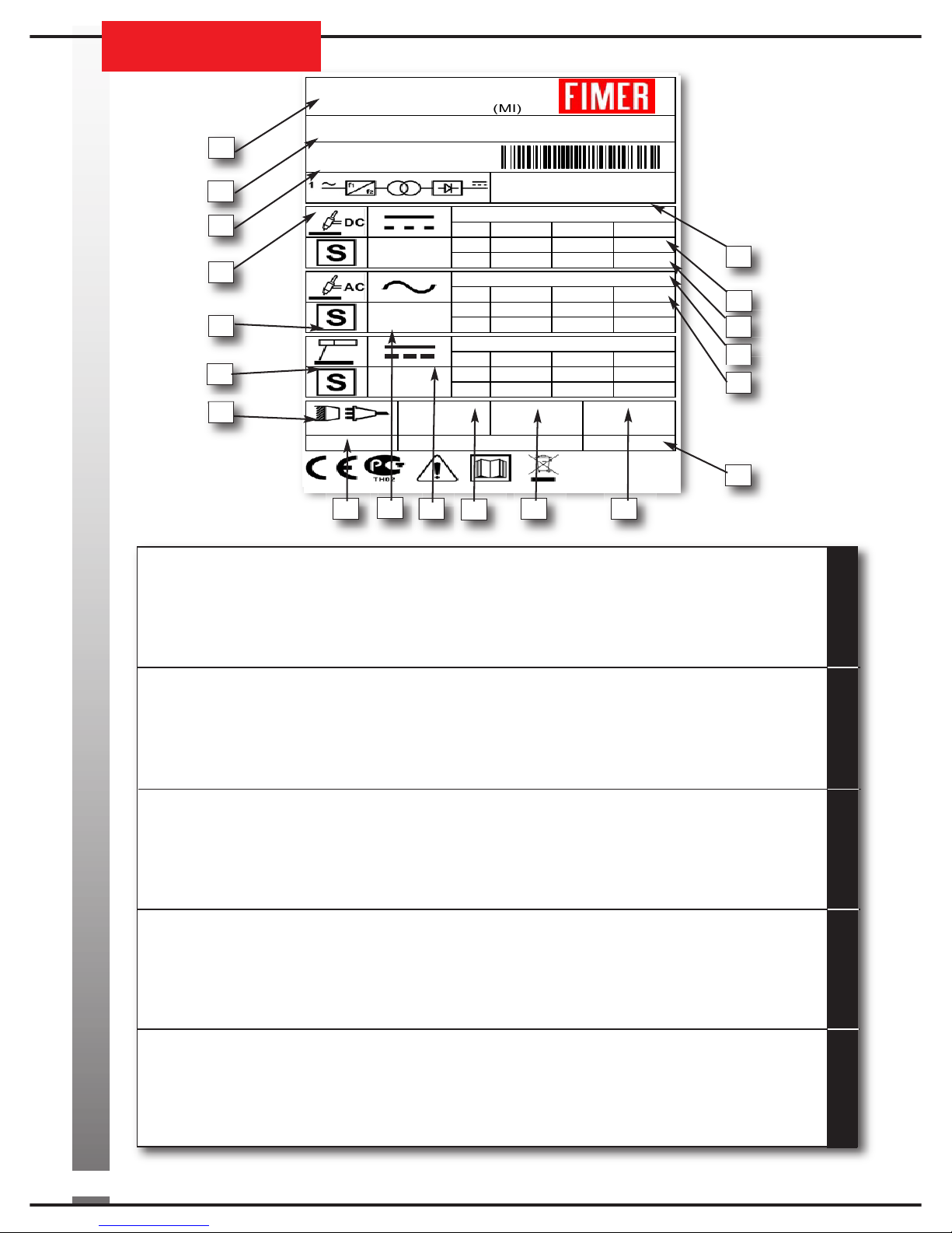
ITALIANO ENGLISH DEUTSCH FRANÇAIS ES AÑOL
1. NOME, INDIRIZZO E LOGO COSTRUTTORE
2. MODELLO
3. NUMERO DI SERIE
4. SCHEMA BLOCCHI
5. USCITA DI SALDATURA
6. UTILIZZABILE IN AMBIENTE
A MAGGIOR RISCHIO DI SCOSSA ELETTRICA
7. ALIMENTAZIONE
8. GRADO DI ROTEZIONE
9. TI O DI CORRENTE DI SALDATURA
10. TENSIONE NOMINALE A VUOTO
11. TENSIONE NOMINALE DI ALIMENTAZIONE
12. MASSIMA CORRENTE NOMINALE DI ALIMENTAZIONE
13. MASSIMA CORRENTE EFFETTIVA DI ALIMENTAZIONE
14. NORME DI RODOTTO
15. RANGE CORRENTE TENSIONE DI SALDATURA
16. CICLO DI INTERMITTENZA
17. CORRENTE NOMINALE DI SALDATURA
18. TENSIONE CONVENZIONALE DI CARICO
19. ANNO DI FABBRICAZIONE
1. MANUFACTURER’S NAME,
ADRESS AND COM ANY LOGO
2. MODEL
3. SERIAL NUMBER
4. BLOCK DIAGRAM
5. WELDING OUT UT
6. SUITABLE FOR USE IN HIGH-VOLTAGE AREAS
7. OWER SU LY
8. DEGREE OF ROTECTION
9. TY E OF WELDING OUT UT CURRENT
10. IN UT VOLTAGE
11. RATED IN UT VOLTAGE
12. MAXIMUM RATED IN UT CURRENT
13. MAXIMUM EFFECTIVE IN UT CURRENT
14. A LICABLE STANDARDS
15. RANGE OF WELDING VOLTAGE-CURRENT
16. DUTY CYCLE
17. RATED WELDING CURRENT
18. CONVENTIONAL LOAD VOLTAGE
19. YEAR OF CONSTRUCTION
1. NOM, ADRESSE ET LOGO CONSTRUCTEUR
2. MODELE
3. NUMERO DE SERIE
4. SCHEMA FONCTIONNEL
5. SORTIE DE SOUDURE
6. UTILISABLE EN MILIEU À RISQUE D’ELECTRIFICATION
ÉLEVÉE
7. ALIMENTATION
8. DEGRE DE ROTECTION
9. TY E DE COURANT DE SOUDAGE
10. TENSION NOMINALE A VIDE
11. TENSION NOMINALE D’ALIMENTATION
12. COURANT NOMINAL D’ALIMENTATION MAXIMUM
13. COURANT EFFECTIF D’ALIMENTATION MAXIMUM
14. NORMES DE RODUIT
15. LAGE DE COURANT/TENSION DE SOUDAGE
16. CYCLE INTERMITTENT
17. COURANT NOMINAL DE SOUDAGE
18. TENSION CONVENTIONNELLE DE CHARGE
19. ANNÉE DE RODUCTION
1. NOMBRE, DIRECCIÓN Y LOGOTI O DEL FABRICANTE
2. MODELO
3. NÚMERO DE SERIE
4. ESQUEMA BLOQUES
5. SALIDA DE SOLDADURA
6. SE UEDE UTILIZAR EN AMBIENTES CON MAYOR
RIESGO DE DESCARGAS ELÉCTRICAS
7. ALIMENTACIÓN
8. GRADO DE ROTECCIÓN
9. TI O DE CORRIENTE DE SOLDADURA
10. TENSIÓN NOMINAL EN VACÍO
11. TENSIÓN NOMINAL DE ALIMENTACIÓN
12. MÁXIMA CORRIENTE NOMINAL DE ALIMENTACIÓN
13. MÁXIMA CORRIENTE EFECTIVA DE ALIMENTACIÓN
14. NORMAS DE RODUCTO
15. ÁMBITO DE LA CORRIENTE DE TENSIÓN DE SOLDADURA
16. CICLO DE INTERMITENCIA
17. CORRIENTE NOMINAL DE SOLDADURA
18. TENSIÓN CONVENCIONAL DE CARGA
19. AÑO DE FABRICACIÓN
1. NAME, ADRESSE UND LOGO DES HERSTELLERS
2. MODELL
3. SERIENNUMMER
4. BLOCKSCHALTBILD
5. SCHWEISSAUSGANG
6. IN UMGEBUNG MIT HÖHERER
STROMSCHLAGGEFAHR VERWENDBAR
7. S EISUNG
8. SCHUTZART
9. SCHWEISSSTROMTY
10. LEERLAUFNENNS ANNUNG
11. NENNS EISES ANNUNG
12. HÖCHSTER NENNS EISESTROM
13. HÖCHSTER EFFEKTIVER S EISESTROM
14. RODUKTNORMEN
15. SCHWEISSS ANNUNGSSTROMBEREICH
16. AUSSETZBETRIEB
17. SCHWEISSNENNSTROM
18. KONVENTIONELLE LASTS ANNUNG
19. BAUJAHR
TARGA DATI, NOMINAL DATA, LEISTUNGSCHILDER LAQUE DON
TARGA DATI, NOMINAL DATA, LEISTUNGSCHILDER LAQUE DONÉ
ÉES, LACA DE CARACTER
ES, LACA DE CARACTERÌ
ÌSTICAS
STICAS