Trafox SUPERINTEND IM-04PV User manual

Superintend IM-04PV Manual v10.571 English Rights to modify the content reserved
© Copyright Muuntosähkö Oy - Trafox 3.2.2022
SUPERINTEND IM-04PV
IMD Insulation Monitoring device for non-grounded (IT) electrical
networks for photovoltaic applications
Instructions for installation and use v10.571
PV
AC/DC

2© Copyright Muuntosähkö Oy –Trafox Superintend IMD
http://www.trafox.fi
Table of Contents
INSTRUCTIONS ..................................................................................................3
SYSTEM DESCRIPTION .......................................................................................4
INSTALLATION ...................................................................................................4
PHYSICAL CONNECTION ..................................................................................... 4
DEVICE MOUNTING............................................................................................ 4
RS-485 NETWORK CONNECTION ......................................................................... 7
SYSTEM CONFIGURATION ................................................................................... 7
USE ....................................................................................................................8
GENERAL .......................................................................................................... 8
IM-04PV UNIT ................................................................................................... 8
MENU STRUCTURE.......................................................................................... 9
MONITOR MENU ........................................................................................... 11
ALARM MENU ............................................................................................... 12
SETUP MENU................................................................................................ 14
ERRORS ...................................................................................................... 16
MODBUS RTU REMOTE CONTROL ................................................................... 16
TECHNICAL SPECIFICATIONS...........................................................................19
IM-04PV UNIT ................................................................................................. 19
HVC-15.100 UNIT ............................................................................................ 19
HVC-15.1000 UNIT .......................................................................................... 20
HVC-15.2000 UNIT .......................................................................................... 20
MECHANICAL DIMENSIONS ............................................................................... 21

Superintend IMD © Copyright Muuntosähkö Oy - Trafox 3
http://www.trafox.fi
INSTRUCTIONS
These instructions for use are intended for trained electrical engineering professionals.
The IM-04PV devices are marked with the symbol shown below, which indicates that if
the device has been installed incorrectly or used in violation of instructions, safety could
be jeopardised. The description of the symbol is presented in this manual instead of on
the device due to space constraints. Such sections are marked with the symbol shown
below.
A symbol indicating possible danger. A description of the symbol may be
placed on the device or provided in the instructions for use.
4© Copyright Muuntosähkö Oy –Trafox Superintend IMD
http://www.trafox.fi
SYSTEM DESCRIPTION
IM-04PV is a device with which the insulation resistance and capacitance of floating
electricity networks can be measured and monitored in photovoltaic applications. A high
voltage coupling device HVC-15.100, HVC-15.1000 or HVC-15.2000 (later abbreviated as
HVC-15.*) is mandatory and it must be used between the IM-04PV and the network to
be monitored. The type of the high voltage coupling device shall be selected so that
maximum leakage capacitance of the network will not exceed the rated maximum
capacitance of the coupling device (HVC-15.100: 100 uF; HVC-15.1000: 1000 uF; HVC-
15.2000: 2000 uF).
INSTALLATION
PHYSICAL CONNECTION
The devices are connected to the electrical network, which may contain
dangerous voltage. The device may be installed by a trained electrical
engineering professional only. The device contains no user-serviceable parts
and must not be opened. Using the device in violation of these instructions
may compromise safety.
The IM-04PV unit is the main unit of the system and is installed in the switchboard. Two
IM-04PV devices may not be installed galvanically in the same network, for example on
the same DC network. The connection is performed as presented in Figure 1. The
installation and wiring should be performed in accordance with standards IEC 60364 as
well as EN 50110. The operating voltage connection of IM-04PV must always be
equipped with a coupler or a line protection switch so that the electricity supply can be
disconnected for the duration of maintenance work, for example. The location of the
disconnectors must be clearly marked in the switchboard. The coupler or line protection
switch should also control a relay or contactor, which separates the measuring wires
from the network to be measured. The IM-04PV device is equipped with an internal 1 A
fuse. In spite of this, the wires of the operating voltage supply should still be protected
with an external fuse. A suitable size is, for example, 6 A. In a DC operating voltage
supply, an external Schurter 0001.2503 (T800mA) fuse should be used.
DEVICE MOUNTING
The IM-04PV and HVC-15.* devices are intended for installation in a DIN TS35 rail in
accordance with standard IEC 60715. They are installed by inserting the upper edge of
the DIN TS35 rail in the groove intended for the DIN TS35 rail on the back of the device
and by pushing the bottom edge of the device backward until the retaining latch clicks
into place.
The IM-04PV unit comes with the connections shown in the following table. The shaded
parts are optional and are installed as needed, while installing the other parts is
mandatory.

Superintend IMD © Copyright Muuntosähkö Oy - Trafox 5
http://www.trafox.fi
Category
Connector
Description
Operating
voltage
connection
Protective earth, to be connected to the earthing circuit connector
+/L
110…240 VAC, 48…62 Hz phase conductor, internal fuse 1A slow
+/-110…300 VDC, use an external fuse Schurter 0001.2503 (T800mA)
-/N
110…240 VAC neutral conductor
-/+110…300 VDC
RS-
485
SH
RS-485 cable shield / ground
A
RS-485 data+ (two-way data)
B
RS-485 data- (two-way data)
Measuring
connectors
TG
Alarm terminal of protective earth, to be connected to the PE rail
MG
Electronics protective earth, to be connected to the PE rail
M1
Connection 1 to HVC-15.*
M2
Connection 2 to HVC-15.*
ISOL.
Not used
Alarm relays
INS. ALARM NO
Alarm relay of the insulation resistance. NO-COM is an open circuit when
the alarm in inactive and closes when the alarm is active. NC-COM
functions in a reverse manner. Max load 250VAC/3A or 30VDC 3A
INS. ALARM NC
INS. ALARM COM
INS. WARN. NO
Pre-alarm relay of the insulation resistance. NO-COM is an open circuit
when the alarm in inactive and closes when the alarm is active. NC-
COM functions in a reverse manner. Max load 250VAC/3A or 30VDC 3A
INS. WARN. NC
INS. WARN. COM
The high voltage coupler HVC-15.* must always be installed between IM-
04PV and the network to be monitored. The network must not be connected
directly to IM-04PV.
The HVC-15.100 and HVC-15.1000 units to be installed in the switchboard have the
following connections, all of which must always be installed.
Connector
Description
M1
Connection 1 to IM-04PV
M2
Connection 2 to IM-04PV
L1
Connection 1 of the network to be monitored; Max 1081VAC/1500VDC
L2
Connection 2 of the network to be monitored; Max 1081VAC/1500VDC
The HVC-15.2000 unit to be installed in the switchboard has the following connections,
all of which must always be installed.
Description
Protective earth, to be connected to the earthing circuit connector
M1
Connection 1 to IM-04PV
M2
Connection 2 to IM-04PV
L1
Connection 1 of the network to be monitored; Max 1081VAC/1500VDC
L2
Connection 2 of the network to be monitored; Max 1081VAC/1500VDC


Superintend IMD © Copyright Muuntosähkö Oy - Trafox 7
http://www.trafox.fi
RS-485 NETWORK CONNECTION
The IM-04PV unit includes a RS-485 bus connection with Modbus RTU protocol for
remote monitoring and controlling.
The IM-04PV unit functions as a slave device. A unique address must be set for it
(SETUP→MB Addr).
The RS-485 bus must form an uninterrupted chain, which is open at both ends, and
contains no branches. Thus, a maximum of two RS-485 cables are installed in any unit:
in other words, an incoming and an outgoing cable. A terminator is installed in the first
and the last unit. If the IM-04PV unit is the first or last device of the bus, an external
terminating resistor of 120 Ω must be connected between the terminals A and B. In all
other units, the terminator must not be installed.
The cable shield is connected to the SH terminal of the IM-04PV unit.
SYSTEM CONFIGURATION
The most sensible configuration order for the settings is as follows:
•Set the correct time (SETUP→Time).
•Set the alarm parameters (SETUP→InsLimit, PrInsLim, StDelay).
•When needed, set the Modbus address (SETUP→MB Addr).
•If needed, enable the automatic alarm acknowledgement (SETUP→AutoRst).
A more detailed description of the configuration is provided in the Manual section “SETUP
menu”.

8© Copyright Muuntosähkö Oy –Trafox Superintend IMD
http://www.trafox.fi
USE
GENERAL
The Superintend IMD PV system based on the IM-04PV unit includes the following
components:
•The IM-04PV unit is the central unit of the system. It performs the
measurements independently and controls the alarm relays. The IM-04PV unit is
installed in the switchboard.
•The HVC-15.* unit is a high voltage coupling device. It is needed between the
IM-04PV and the network to be monitored. The HVC-15.* unit is installed in the
switchboard.
IM-04PV UNIT
The IM-04PV unit is the central unit of the system. The IM-04PV contains the user
interface of the entire system. The error notifications are displayed on the screen of the
IM-04PV, and the fault information can be forwarded to another user-defined system
through the alarm and pre-alarm relays. All alarm parameters are set through the user
interface of the IM-04PV system.
Measurement values can be monitored and settings can be changed using the Modbus
RTU protocol via the IM-04PV unit’s RS-485 connection. For this purpose, the device
must be connected to a RS-485 bus and the Modbus address must have been configured
in the Setup menu.
The IM-04PV unit independently measures the insulation resistance and capacitance of
the IT network to be monitored, in relation to protective earth. The measurement is
performed by feeding two summed low frequency alternating voltages between the
network and the PE conductor. These generate a low current that travels through the
insulation resistance and capacitance to be measured. The insulation resistance and
capacitance are calculated by FFT analysing the current and then measuring the
amplitude and phase.

Superintend IMD © Copyright Muuntosähkö Oy - Trafox 9
http://www.trafox.fi
The system functioning can be tested by pressing the T button of the IM-04PV unit when
the IM-04PV unit displays the Monitor menu. The device will test the functioning of the
internal measurement circuit. More detailed information on this is provided in the
description of the Monitor menu.
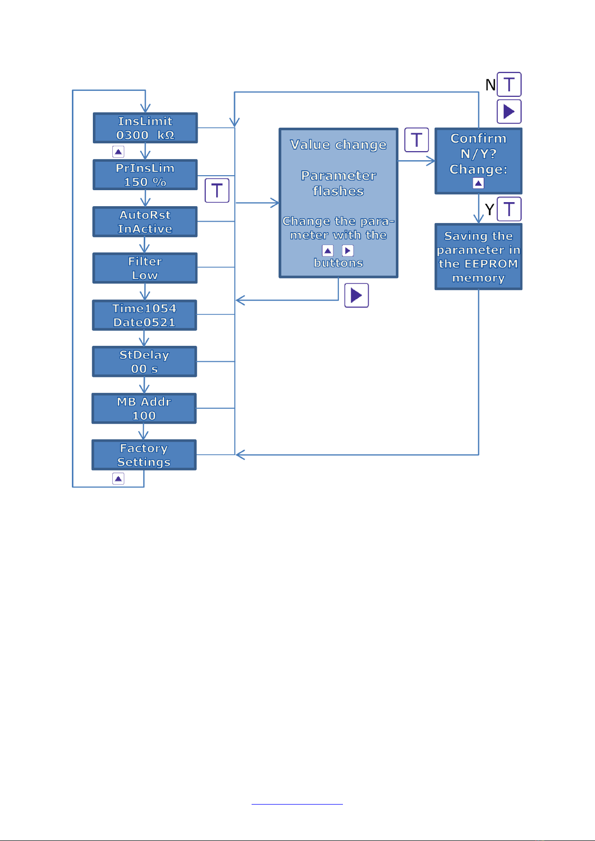
MENU STRUCTURE
The menus of the IM-04PV unit have three main levels: MONITOR, SETUP and ALARM.
The button is used to navigate between the main levels when the topmost parameter
of each menu is highlighted on the screen.
The menus can be browsed down with the button. Access to the Setup menu is
password-protected.
The Monitor menu is the default of the IM-04PV unit, to which the system returns in 20
minutes after the last time a button was pressed, or after a sufficient number of presses
on the button in any screen mode.
•The Monitor menu mainly has one level. All information to be displayed can be
viewed by browsing the menu with the button.

10 © Copyright Muuntosähkö Oy –Trafox Superintend IMD
http://www.trafox.fi
•The Alarm menu has two levels. The first level displays the reason for the alarm
and the second level shows the alarm start time, the measured parameters, and
alarm limits.
•The Setup menu mainly has two levels. The first level displays the valid
parameter, which can be changed on the second level.
Hereafter, the screen modes are called as follows:
•The main level of the menu is the topmost menu level (MONITOR, SETUP and
ALARM)
•The menu level is the sub-level of the aforementioned, and it is browsed using
the button
•The screen mode is the mode following the menu level, and it displays the value
of the parameter/time; also displays a stopped AutoScroll mode. The screen
mode can be accessed from the menu level by pressing the T button.
•The AutoScroll mode is in use in the Setup menu items where there are several
parameters to display. In that case, the displayed parameters change every few
seconds. You can stop the display with the button and return from the screen
mode to the AutoScroll mode with the button. Use the T button to go to the
edit mode or screen mode.
•The Edit mode is a Setup menu mode where the parameters to be displayed can
be changed. In the Edit mode, the parameter to be changed flashes and it can be
changed with the button. If there are several parameters to be changed in the
same screen, you can move to the next one by pressing the button. After the
editing is completed, press the T button, after which the values given must be
approved by selecting “Yes” in the Confirm menu and pressing T. By selecting
“No” or pressing the button in the conformation stage you return to the
previous mode without saving the changes.
As a rule, the buttons function as follows:
Moving to the next parameter on the menu level and screen level. Increases the
parameter on the edit level. In the AutoScroll mode, stops the display.
Moving to the next menu on the main level. Moves to the next editable
parameter on the edit level. Also a general “reject button”. Returns to the
previous mode from all modes. Pressing the button an appropriate number of
times takes you to the default mode of the main menu (insulation
resistance/capacitance) from any mode.
A general “approval button”. On the menu level, takes you to the AutoScroll or
edit mode. On the edit level, approves the changes made. Pressing the button
in the first three items of the Monitor menu and approving the start of the test
begins the system test.

Superintend IMD © Copyright Muuntosähkö Oy - Trafox 11
http://www.trafox.fi
MONITOR MENU
The Monitor menu is the default menu of the IM-04PV unit during use. All modes of the
menu always return to the topmost item on the Monitor menu after 20 minutes from the
last press of a button.
The following measured parameters are available in the Monitor menu screen:
•IT network’s insulation resistance and capacitance in relation to protective earth.
Displayed in kOhms and micro farads.
•Time and date
•All fixed alarms can be acknowledged on one go.
•Firmware version
The default display is insulation resistance and capacitance. Other parameters and
functions can be viewed by using the button.
The system test is started from the Monitor menu by pressing T and then selecting Y in
the Start test menu and pressing T. This starts the test of the internal measurement
circuit of the IM-04PV unit. If the test is completed successfully, the screen displays
momentarily the text Test OK; otherwise the text shown in Test FAILED, and an
insulation fault alarm is given to indicate that the insulation resistance can no longer be
measured.
The Monitor menu functions as follows:

12 © Copyright Muuntosähkö Oy –Trafox Superintend IMD
http://www.trafox.fi
ALARM MENU
The alarm menu has two levels. The menu level shows if the alarm is active (ALARM),
inactive but not acknowledged (OLD ALRM) or if the situation is normal (OK). The
screen mode shows the value, alarm limit and time of the parameter that caused the
alarm.
If the start-up delay has been enabled (SETUP→StDelay), the alarms cannot be
activated before the set start-up delay has been elapsed after powering on the unit.
An alarm always indicates that the fault in question is still active. An active fault cannot
be acknowledged until the issue that caused it has been fixed. The fixed fault is
acknowledged when its time is checked and the T button is pressed. The button takes
you back to the menu level without acknowledging the fault.
All fixed faults can also be acknowledged on one go by means of the Alarm reset function
in the Monitor menu.
If the automatic alarm acknowledgement has been enabled (SETUP→AutoRst), the faults
are acknowledged automatically as soon as they are fixed.

Superintend IMD © Copyright Muuntosähkö Oy - Trafox 13
http://www.trafox.fi
All alarms except pre-insulation (PreInsul) alarm are indicated by the red LED light
ALARM, which BLINKS in fault situations and is on STEADILY if the fault has been fixed
but not acknowledged (the OLD ALRM mode). The alarms which are related to
disconnected measurement wires or internal errors, are indicated also with the red
STATUS light. The pre-insulation alarm is indicated in the same way with the red LED
light WARN.
The insulation resistance fault activates IMMEDIATELY when the measured parameter
drops below the alarm limit. The alarms have a five-percent hysteresis. In other words,
an alarm becomes active when the set limit is reached, but it is deactivated only when
the measured value deviates by 5% in a safe direction from the limit given.
The screen mode of each parameter alternately displays the following:
•On the top row, the value / fault limit of the parameter that caused the fault, and
on the bottom row, the current status: OK, ALARM or OLD ALRM
•Fault start time and date
If the fault has been deactivated and becomes active again, the start time of the active
fault is displayed. In the OK mode, nothing is displayed in the screen mode.
The screen always displays the measured quantity (the smallest value measured during
the fault) / fault limit of the fault first, followed by the fault start time.
The insulation fault alarm is active.
The smallest insulation resistance measured during the fault is
850 kΩ and the alarm limit is 900 kΩ.
The insulation fault alarm has been deactivated but not
acknowledged.

14 © Copyright Muuntosähkö Oy –Trafox Superintend IMD
http://www.trafox.fi
The smallest insulation resistance measured during the fault, the alarm limit's set value
and the fault start time are displayed.
The Insulat. and PreInsul alarms are active if the measured insulation resistance is
smaller than the alarm or pre-alarm limit.
The Sys Test alarm is active if the manual system test fails. In that case, the insulation
resistance can not be measured either, so an insulation resistance alarm is also given.
The Gnd Fail alarm is active if the TG or MG wire of the IM-04PV unit is disconnected. In
that case, the insulation resistance can not be measured either, so an insulation
resistance alarm is also given.
SETUP MENU
The Setup menu can be used to change system settings, alarm limits, time etc.
The Setup menu is password-protected and accessed as follows:
•Go to the Setup menu in the main menu. The screen displays “Enter Setup”.
Press T.
•Change the blinking number with the button and press the button to move
to the next digit. Enter the three digits and press T. After this, you can navigate
the menu with the button.
•The button takes you to the initial mode.
The password is “123”.
All information on the settings of the device alarm limits and the system are saved in the
internal EEPROM memory of the IM-04PV unit.
Superintend IMD © Copyright Muuntosähkö Oy - Trafox 15
http://www.trafox.fi
The following parameters can be changed in the Setup menu:
•INSULATION LIMIT: Alarm limit of the insulation resistance. If the measured
value is lower than the alarm limit, an alarm is given. The setup range is 10…100
kΩ with 10 kΩ intervals and 100 kΩ…1,000 kΩ with 50 kΩ intervals.
•PRE INSULATION LIMIT: The pre-insulation limit of the insulation resistance.
Given as a percentage of the insulation limit. Activates the INS. WARN. relay.
The setup range is 100…200%, at 10% intervals.
•AUTOMATIC ALARM ACKNOWLEDGEMENT: This setting determines whether
all the alarms shall be acknowledged automatically as soon as they are
deactivated.
•Filter: Not in use.
•TIME: The time and date of the real time clock.
•START-UP DELAY: The delay after powering on the unit during which the alarms
will not be generated. The setup range is 0…60 s.

16 © Copyright Muuntosähkö Oy –Trafox Superintend IMD
http://www.trafox.fi
•MODBUS ADDRESS: The Modbus slave address of the unit. The setup range is
1…247.
•FACTORY SETTINGS: Returns all settings to their original values.
ERRORS
The following table lists the functioning of the IM-04PV unit in various error situations.
Error
IM-04PV
ALARM
LEDs
IM-04PV
ALARM
menu
Alarm
relay
The IM-04PV unit without
operating voltage
ALM WRN
Insulation fault (R under
InsLimit)
ALARM
Insulat.
ALM
Insulation fault (R under
PrInsLim)
WARN
PreInsul
WRN
The IM-04PV unit TG wire
is disconnected
STATUS ALARM
Gnd Fail
ALM
The IM-04PV unit MG wire
is disconnected
STATUS ALARM
Gnd Fail
ALM
System fault (manual
test)
STATUS ALARM
Sys Test
ALM
Alarm relays:
•ALM insulation alarm
•WRN insulation pre-alarm
Error situations are displayed by means of ALARM LEDs and the alarm menu of the IM-
04PV unit. A blinking LED always means that an alarm is active, and a steady indicator
indicates a fixed and unacknowledged fault.
MODBUS RTU REMOTE CONTROL
When a suitable Modbus address has been set for the IM-04PV unit, the device can be
connected to a RS-485 bus. The unit's Modbus RTU slave functionality is now ready for
use. The unit’s Modbus RTU register map is provided below. The Modbus functions to be
used are Read Holding Registers (0x03) and Write Multiple Registers (0x10).

Superintend IMD © Copyright Muuntosähkö Oy - Trafox 17
http://www.trafox.fi
Register
R/W
Name
Type
Unit
Description
1
R
Measured insulation resistance
uint16
kOhm
The measurement result is provided as kOhms. The
register value 100 corresponds to insulation
resistance of 100,000 ohms. At the fastest, it
updates in seconds and at the slowest in hundreds of
seconds, depending on the measurement frequency
used.
2
R
Measured capacitance
uint16
0.1
uF
The measurement result is provided as 0.1uF
intervals. The register value 5 corresponds to
capacitance of 0.5uF. It is updated at the same time
as the insulation resistance.
5
R/W
Limit parameter of the
insulation resistance alarm
uint16
kOhm
Read and written in kOhms. The register value 100
corresponds to 100,000 ohms. The minimum,
maximum and interval values are in channels 16, 17
and 18.
6
R/W
The limit parameter of the
insulation resistance pre-alarm.
uint16
%
Read and written in percentages. The register value
150 corresponds to 150%. The minimum, maximum
and interval values are in channels 19, 20 and 21.
10
R/W
Start-up delay, a device
parameter
uint16
s
Read and written in seconds. The register value 2
corresponds to 2 seconds. The minimum, maximum
and interval values are in channels 31, 32 and 33.
11
R
Password of the local user
interface
uint16
none
A three-digit password. Range 000…999. Default
value 123. When needed, this can be used to prevent
the parameters from being set through the Modbus
RTU.
12
R
Device alarm and status
register
uint16
none
Bit mask:
0x0001 = a fault or alarm related to insulation
resistance, corresponds to the INSULATION alarm
LED of the local user interface
0x0002 = insulation resistance pre-alarm
0x0004 = system test fault
0x0010 = fault in the TG or MG wire
0x0100 = system test active
0x0200 = internal calibration active (the insulation
level measurement values are invalid)
the statuses remain active until their cause has been
eliminated
13
R/W
Start of the device system test
uint16
none
Start of the system test. Value 1 starts the test,
other values are not taken into account. IM-04PV
resets the request after reading it.
15
R/W
Joint acknowledgement of
alarms
uint16
none
Joint acknowledgement of unacknowledged alarms.
Value 1 acknowledges all alarms, other values are
not taken into account. IM-04PV resets the request
after reading it. This does not acknowledge/inactivate
active alarms.
16
R
The lowest allowed value of the
limit parameter of the insulation
resistance alarm
uint16
kOhm
10
17
R
The highest allowed value of the
limit parameter of the insulation
resistance alarm
uint16
kOhm
1000
18
R
The resolution (jog) of the limit
parameter of the insulation
resistance alarm
uint16
kOhm
50 if insulation resistance alarm limit 100 kOhm or
above
10 if insulation resistance alarm limit below 100
kOhm
19
R
The lowest allowed value of the
limit parameter of the insulation
resistance pre-alarm
uint16
%
100
20
R
The highest allowed value of the
limit parameter of the insulation
resistance pre-alarm
uint16
%
200
21
R
The resolution (jog) of the limit
parameter of the insulation
resistance pre-alarm
uint16
%
10
31
R
Start-up delay, the lowest
allowed value of the device
parameter
uint16
s
0

18 © Copyright Muuntosähkö Oy –Trafox Superintend IMD
http://www.trafox.fi
32
R
Start-up delay, the highest
allowed value of the device
parameter
uint16
s
60
33
R
Start-up delay, the device
parameter resolution (jog)
uint16
s
1
34
R
Status register of the
unacknowledged alarms of the
device
uint16
none
Bit mask:
0x0001 = a fault or alarm related to insulation
resistance is inactivated, corresponds to the
INSULATION alarm LED of the local user interface
0x0002 = insulation resistance pre-alarm deactivated
0x0004 = system test fault deactivated
0x0010 = fault in the TG or MG wire deactivated
the statuses will activate when the corresponding
active alarm has been deactivated and remain active
until the cause has been acknowledged

Superintend IMD © Copyright Muuntosähkö Oy - Trafox 19
http://www.trafox.fi
TECHNICAL SPECIFICATIONS
IM-04PV UNIT
Voltage ranges
•Operating voltage [US]:
110…240VAC, frequency 48…62 Hz
110…300VDC (use an external fuse Schurter 0001.2503 (T800mA))
•Frequency range of the network to be monitored: DC, 10…460Hz
•Input power: 3W. Internal fuse of the operating voltage: 1AT
Monitoring of the insulation level:
•Measurement voltage [Um]: ± 25Vp
•Alarm limit [Ran]: 10kΩ…1MΩ
•Hysteresis: 5%
•Start-up delay: 0…60s
Alarm switches
•5A (NO) / 3A (NC) @ 30VDC for resistive load
•5A (NO) / 3A (NC) @ 277VAC for resistive load
•Maximum power: 1400VA / 150W (NO) and 850VA / 90W (NC)
•Insulation strength between contacts: 1000VAC 50/60Hz 1 min
•Useful life: 100,000 connections with the maximum nominal load
Other details
•Operating temperature: 0…50ºC, relative humidity: < 90%, non-condensing
•IP class (front panel): IP40
•IP class (other casing): IP20
•Connector tightening torque: 0.45…0.5 Nm
•Weight: 180 g
•Not suitable for connecting in parallel
•EMC standards: EN61326-2-4, EN55011, EN61000-4-2, EN61000-4-3, EN61000-
4-4, EN61000-4-5, EN61000-4-6, EN61000-4-11
•Other standards: IEC61557-8, IEC61010-1:2010-3
HVC-15.100 UNIT
Voltage ranges
•Maximum voltage at the measurement connectors L1 and L2 [UN]: 1500VDC or
1081VAC
•Maximum leakage capacitance: 100 uF

20 © Copyright Muuntosähkö Oy –Trafox Superintend IMD
http://www.trafox.fi
Monitoring of the insulation level:
•Measurement circuit impedance: 308kΩ
•Relative uncertainty:
o10kΩ…1MΩ: ±15%
o5kΩ…10kΩ: ±3kΩ
Other details
•Operating temperature: 0…50ºC, relative humidity: < 90%, non-condensing
•IP class (front panel): IP40
•IP class (other casing): IP20
•Connector tightening torque: 0.5…0.6 Nm
•Weight: 94 g
HVC-15.1000 UNIT
Voltage ranges
•Maximum voltage at the measurement connectors L1 and L2 [UN]: 1500VDC or
1081VAC
•Maximum leakage capacitance: 1000 uF
Monitoring of the insulation level:
•Measurement circuit impedance: 99kΩ
•Relative uncertainty:
o10kΩ…1MΩ: ±15%
o5kΩ…10kΩ: ±3kΩ
Other details
•Operating temperature: 0…50ºC, relative humidity: < 90%, non-condensing
•IP class (front panel): IP40
•IP class (other casing): IP20
•Connector tightening torque: 0.5…0.6 Nm
•Weight: 201 g
HVC-15.2000 UNIT
Voltage ranges
•Maximum voltage at the measurement connectors L1 and L2 [UN]: 1500VDC or
1081VAC
•Maximum leakage capacitance: 2000 uF
Table of contents
Other Trafox Measuring Instrument manuals


