Trail-Tec WYR150407R User manual
Anbauanweisung
Bitte klemmen Sie das Massekabel an der Batterie ab!
Bauen Sie die folgenden Abdeckungen und Verkleidungen im Innenraum heraus: Hutablage,
Heckblechverkleidung, Kofferraumbodenabdeckung mit Aufbewahrungsfächern, linke und rechte
Seitenverkleidung im Kofferraum, linke Einstiegsleistenverkleidung Fahrer und Fond, Verkleidung der vorderen A-
Säule und die untere Verkleidung der Instrumententafel. Bauen Sie die linke und rechte Rückleuchteneinheit ab.
Zur Durchführung des Kabelstranges (Anschluss Steckdose) entfernen Sie auf der linken Seite am Bodenblech vor
der Zwangsentlüftung den Stopfen. Verlegen sie den Leitungsstrang 7polig (Kit 150407) und 12polig (Kit 150413)
vom inneren des Kofferraumes durch die Durchführung nach außen. Die Gummidurchführungstülle entsprechend
einbringen.
Der Kabelsatz ist wie folgt belegt:
a) Das Leitungssatzende 7polig (Kit 150407) und 12polig (Kit 150413) durch das Loch am Steckdosenhalter
verlegen.
b) Beiliegende Gummidichtung für die Steckdose entsprechend verwenden. (geeignetes Gleitmittel
verwenden!)
c) Den vorkonfektionierten Kontakteinsatz vom Leitungssatz in die Steckdose einstecken und verrasten:
1.
2.
3.
4.
Inhalt: 1 Leitungsstrang 1 Klettband 1 Schraube M5 x 10 10 Kabelbinder 100mm
1 Steckdose 1 Gummitülle 3 Schrauben M5 x 35 1 Sicherungshalter
1 Steckdosendichtung 1 Blechschraube 4 Muttern M5 1 Sicherung 15A
1 Modul UN-09 4 Sprengringe 4 Kabelbinder 300mm (nur bei 13 pol)
1 Anschlußleitung rot 1 Abzweigschnellverbinder
Elektrischer Anbausatz für Anhängerkupplung
7 polig Art.-Nr. :<51504075
13 polig Art.-Nr. :<51504135
Hyundai Santa Fe
ab Bj
03.06 – 09.12
150407/13 5
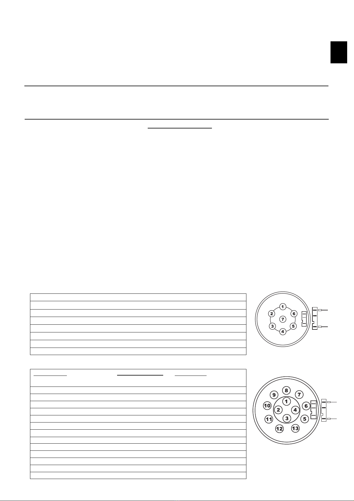
Stromkreis:
Blinker links
Nebelschlußleuchte Anhänger
Masse 1-8
Blinker rechts
Schlußleuchte rechts
Bremsleuchte
Schlußleuchte links
Kabelfarbe :
schwarz / weiß
grau
braun
schwarz / grün
grau / rot
schwarz/rot
grau / schwarz
Kontaktbelegung:
1(L)
2 (54-G)
3 (31)
4(R)
5 (58-R)
6 (54)
7 (58-L)
Bild 1
Kontaktbelegung
der Steckdose
Kontaktbelegung
der Steckdose
D
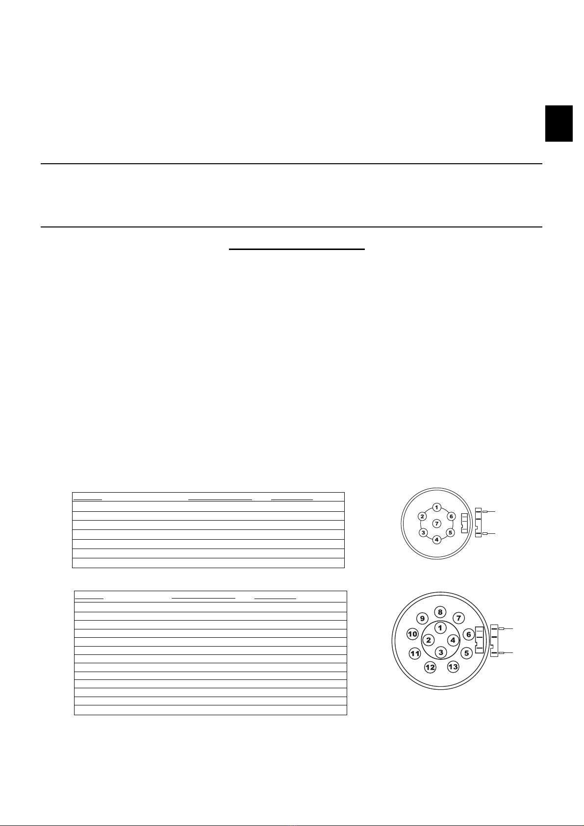
Stromkreis:
Blinker links
Nebelschlußleuchte Anhänger
Nebelschlußleuchte KFZ
Masse 1-8
Blinker rechts
Schlußleuchte rechts
Bremsleuchte
Schlußleuchte links
Rückfahrleuchte
Dauerplus Anhänger
Ladeleitung
Masse für Ladeleitung
Frei
Masse für Dauerplus
Kabelfarbe :
schwarz / weiß
grau
grau / weiß
braun
schwarz grün
grau / rot
schwarz / rot
grau / schwarz
blau / rot
rot / blau 2,5mm²
gelb 2,5mm2
weiß / braun 2,5mm²
frei
weiß / braun 2,5mm²
Kontaktbelegung:
1 (L)
2 (54-G)
2a
3 (31)
4 (R)
5 (58R)
6 (54)
7 (58L)
8 (RFS)
9 (30)
10 (15)
11 (31)
12
13 (31)
Bild 2
bk/rd
bu/rd
bk/rd
bu/rd

Den weißen 2x1-fach Stecker seitlich in der Steckdose auf den Microschalter aufstecken. Die Gummidichtung und
Steckdose mit den beiliegenden Schrauben und Muttern am Steckdosenhalter befestigen.
a) Auf ordnungsgemäßen Sitz der Dichtung achten!
b) Leitungssatz so verlegen, dass keine Scheuer- oder Knickstellen entstehen können!
Das Leitungssatzende das mit L gekennzeichnet ist, entlang zu der linken Rückleuchte zum fahrzeugseitigen
Steckgehäuse 4-fach verlegen und das fahrzeugseitige Steckgehäuse 4-fach der linken Rückleuchte
entfernen.
a) Das fahrzeugseitige Steckgehäuse 4-fach der linken Rückleuchte mit den passenden Gegenstück des
Leitungssatzes zusammenstecken und verrasten.
b) Das verbleibende Steckgehäuse 4-fach des Leitungssatzes auf den Stecker der linken Rückleuchte
stecken und verrasten.
c) Das beiliegende Modul auf das Steckgehäuse 14-fach des Leitungssatzes stecken und an geeigneter
Stelle mit der Schraube M5x10 und Kabelbindern befestigen. Es ist besonders darauf zu achten, das
keine Feuchtigkeit in das Modul eindringen kann (Kurzschlussgefahr).
d) Die Ringöse der Leitung braun (und weiß / braun 2,5 mm² bei 13pol) an einen geeigneten
Massepunkt anschließen. (ggf. 3 mm Loch bohren und mit beiliegender Blechschraube befestigen.
Bohrung nicht mit Korrosionsschutz behandeln.)
Das Leitungssatzende das mit Rgekennzeichnet ist, entlang zu der rechten Rückleuchte zum fahrzeugseitigen
Steckgehäuse 4-fach verlegen und das fahrzeugseitige Steckgehäuse 4-fach der rechten Rückleuchte
entfernen.
a) Das fahrzeugseitige Steckgehäuse 4-fach der rechten Rückleuchte mit den passenden Gegenstück
des Leitungssatzes zusammenstecken und verrasten.
b) Das verbleibende Steckgehäuse 4-fach des Leitungssatzes auf den Stecker der rechten Rückleuchte
stecken und verrasten. Die Rückleuchte wieder montieren.
Anschluss Nebelschlussleuchte und Rückfahrscheinwerfer:
Die vorhanden 2-fach Steckgehäuse des Leitungssatzes zur Stoßstange verlegen. Dort den befindlichen
2-fach Stecker der Nebelschlussleuchte entfernen und mit dem entsprechenden Gegenstück des
Leitungssatzes verbinden. Die verbliebenen 2-fach Stecker des Leitungssatzes auf die Nebelschlussleuchte
stecken.
Anschluss Rückfahrscheinwerfer (nur bei 13 pol):
Den Flachstecker vom Kabel blau / rot des Leitungssatzes zur rechten Rückleuchteneinheit verlegen. Die
Funktion Rückfahrscheinwerfer mit einem Spannungsprüfer ausmessen und den Abzweigschnellverbinder
ancrimpen. Den Flachstecker vom Kabel blau / rot der Leitungssatzes auf den Abzweigschnellverbinder
aufstecken.
Fahrzeuge ohne Einparkhilfe (PDC)
Die Crimpehülsen vom schwarz / roten und blau / roten Kabel des Leitungssatzes enden lose in der
rechten Kofferraumseitenverkleidung (werden nicht benötigt, Leitungssatzenden isolieren).
Fahrzeuge mit Einparkhilfe (PDC) Steuergerät rechts über dem Radlauf
Die Crimpehülsen vom schwarz / roten und blau / roten Kabel des Leitungssatzes zum Steuergerät der
Einparkhilfe verlegen. Das Kabel mit der Funktion Rückfahrscheinwerfer an geeigneter Stelle trennen. Beide
Enden ca. 5 mm ab isolieren. Die Crimpehülse vom schwarz / roten Kabel des Leitungssatzes am
abisolierten Kabel, welches zum Stecker des Steuergerätes Einparkhilfe (PDC) führt, anschließen. Die
Crimpehülse vom blau / roten Kabel des Leitungssatzes am abisolierten Kabel, welches vom
Rückfahrscheinwerfer kommt, anschließen.
5.
6.
7.
8.
9.
10.
11.

Spannungsversorgung Modul
a) Die Spannungsversorgung erfolgt direkt an der Batterie.
b) Das rote Kabel entlang dem fahrzeugeigenen Kabelbaum auf der linken Seite zur Batterie hin in den
Motorraum verlegen. Das Kabel durch die Kabeldurchführung vom originalen Fahrzeugkabelbaum führen
und mit den vorhanden Kabelbindern befestigen. Die Durchführung mit Silikon abdichten.
c) Die Leitung weiter zur Batterie verlegen.
d) Die Ringöse der roten Einzelleitung am Pluspol der Batterie anschließen.
Stromversorgung Anhänger:
Das Steckgehäuse 3-fach (Leitungen rot/blau, gelb und weiß/braun) ist für eine Erweiterung der
Steckdosenfunktionen vorgesehen. Dieses Teil des Leitungssatzes hinter die Verkleidung legen. Für die
Erweiterung der Steckdosenfunktionen kann ein Erweiterungssatz bestellt werden.
Funktion Dauerplus und Masse Bestellnr. :<59907995
Funktion Dauerplus, Ladeleitung und Masse Bestellnr. :<59916995
Funktionshinweis Anhänger-Blinküberwachung:
Ein Defekt der Blinker des Anhängers wird im Anhängerbetrieb von der fahrzeugseitigen Kontrollleuchte über eine
Erhöhung der Blinkfrequenz angezeigt!!
Alle Leitungsstränge mit beiliegenden Kabelbindern befestigen, alle Verkleidungen und demontierten Teile wieder
einbauen.
Der Elektrosatz ist nicht diagnosefähig und das Bordnetzsteuergerät wird nicht codiert.
Die Batterie wieder anschließen und sämtliche Fahrzeugfunktionen mit angeschlossenem Anhänger oder einem
geeigneten Prüfgerät überprüfen.
Die Einbauanleitung ist dem Kunden auszuhändigen!!!
12.
13.

Installation instruction
Disconnect the earth lead from the battery.
Remove the following interior covers and cladding: rear rack, rear belt lining, trunk plate with storage
compartments, left and right side lining in the trunk, left threshold lining at the driver and rear seat, front body pillar
(A) lining and bottom dashboard lining. Remove left and right rear composite lamp.
To route the wiring harness (plug connector), remove the plug on the left side of the flooring sheet in front of the
ventilation grille and route the 7-pin (set 150407) and 12-pin (set 150413) wiring harness from the inside of the
trunk through the bushing and fit the rubber cable bush accordingly.
The connection of the cable set proceeds as follows:
a) Route the end of the 7-pin (set 150407) and 12-pin (set 150413) cable sets through the opening in the
holder of the socket.
b) Pull the provided rubber seal for the socket onto the wiring set terminal. (Apply appropriate antiadhesive
agents!)
c) c) Plug in the prefabricated contact insert of the cable set into the socket and lock it in place:
1.
2.
3.
4.
Packing list:1 Cable set 1 Self-adhesive tape 1 Screws M5 x 10 10 Cable ties 100mm
1 Socket 1 Rubber cable bush 3 Screws M5 x 35 1 Fuse base
1 Socket retaining plate 1 Sheet metal screw 4 Nuts M5 1 Fuse 15A
1 Module UN-09 4 Spring washer 4 Cable ties 300mm ( in 13-polar set)
1 Red connection cable 1 Quick connection
Electrical Set for Trailer Connection
7-pin Part no.
:<51504075
13-pin Part no.
:<51504135
Hyundai Santa Fe
manufactured
03.06 – 09.12
150407/135
Contact description in
7-pin socket
Function
Indicator left
Fog light
Earth
Indicator right
Tail light right
Stop light
Tail light left
Cable colour
black/white
grey
brown
black/green
grey/red
black/red
grey/black
Contact description
1(L)
2 (54-G)
3 (31)
4(R)
5 (58-R)
6 (54)
7 (58-L)
Picture1
Contact description in
13-pin socket
Function
Indicator left
Trailer fog light
Earth
Indicator right
Tail light right
Stop light
Tail light left
Reversing light
Trailer current supply
Charge line plus
Charge line earth
Not assigned
Earth (trailer)
Cable colour
black/white
grey
brown
black/green
grey/red
black/red
grey/black
blue/red
red/blue 2,5mm
2
yellow 2,5mm
2
white/brown 2,5mm
2
white/brown 2,5mm
2
Contact description
1
2
3
4
5
6
7
8
9
10
11
12
13
GB
bk/rd
bu/rd
bk/rd
bu/rd

Fit the white 2x1 plug on the side of the socket on the micro switch. Attach the rubber gasket and the socket to the
socket holder using the supplied screws and nuts.
a) Pay special attention to the right position of rubber retaining plate,
b) Put the cable set gently to avoid any folds and to secure it from possible wiping.
Route the end of the wiring harness marked Lalong the left rear lamp to the 4-P vehicle body and disconnect the
4-P vehicle body of the left rear lamp.
a) Connect the 4-P socket of the left rear lamp in the vehicle with the matching counterpart of the wiring kit
and lock.
b) Connect the other 4-P socket of the wiring kit to the plug of the left rear lamp and lock.Reinstall the rear
lamp.
c) Connect the provided module to the 14-P of the wiring kit and lock in a proper location with a
provided M5 x 10 screw and band clips. Take proper precautions to protect the module from humidity
(danger of short circuit).
d) Connect the eye terminals of the 2 x brown (and 13-P white/brown 2.5 mm2)wires to an appropriate
grounding point (pillar D) (if necessary, drill a 3 mm hole and fix with a provided self-tapping screw; do not
protect the drilled hole with anticorrosive agents).
Route the end of the wiring harness marked with Ralong the right rear lamp to the 4-P body of the vehicle and
disconnect the 4-P body of the vehicle’s right rear lamp.
a) Connect the 4-P socket of the right rear lamp in the vehicle with the matching counterpart of the wiring kit
and lock.
b) Connect the other 4-P socket of the wiring kit to the plug of the right rear lamp and lock.Reinstall the rear
lamp.
Connecting the rear fog lamp and the reversing lamp:
Route the available 2-P housing of the cable set to the bumper. Remove the double lamp connector of the rear fog
lamp and connect it to the corresponding plug in the cable set. Connect the remaining double connectors of the
wiring harness to the rear fog lamp.
Connecting the reversing lamp connector (13 pins only):
Route the blue/red cable’s flat plug of the cable set to the right rear composite lamp. Measure the operation of the
reversing lamp with the voltage tester and tighten the quick-release coupling. Plug the blue/red cable's flat plug of
the cable set to the quick coupler.
Vehicles without parking distance control (PDC)
Collets of black/red and blue/red wires of the wire set end loosely in the right side of the trunk lining (are not
required; the ends of the wire set need to be insulated).
Vehicles equipped with a parking assistant (PDC) with the controller located at the left side over the inner
wheel well
Lead the collets of black/red and blue/red wires of the wire set into the parking assistant control unit. Disconnect
the cable with the reversing lamp function at the proper place. Remove the insulation from both ends at the length
of approximately 5 mm. Connect the collet of black/red wire of the wire set to the wire with the insulation removed,
leading to the connector of the parking assistant control unit (PDC). Connect the collet of blue/red wire of the wire
set to the reversing lamp wire with the insulation removed.
10.
5.
6.
7.
8.
9.
11.

Power supply module
a) Power is provided directly from the battery.
b) Route the red wire along the on-board wire harness on the left side towards the battery in the engine
compartment. Route the wire through the bushing of the original cable bush of the vehicle and secure it
with the available cable ties. Seal the bushing with silicone.
c) Route the wire further towards the battery.
d) Connect the red wire end of the single wire to the positive terminal of the battery.
Trailer power supply:
3-pin connector housing (red/blue, yellow, and white/brown cables) is provided for expanded socket functions. Put
this part of cable set behind the trim. To expand socket functions it is necessary to order the following parts:
Function “current supply and earth” part no. :<59907995
Function “current supply, charge line and earth” part no. :<59916995
Remarks regarding trailer indicator operation:
Trailer indicator defect is signalled by a control light of the vehicle by increased flashing frequency!!
Fix all the leads with supplied band clips, assemble previously disassembled parts.
The electric set is not trouble-shootable and the deck network control is not coded.
Connect accumulator and check all vehicle functions with connected trailer or other suitable testing device.
Assembly instruction for the customer.
13.
12.
This manual suits for next models
1
Table of contents
Languages:
Other Trail-Tec Automobile Accessories manuals


Popular Automobile Accessories manuals by other brands


Havis-Shields
Havis-Shields WGI-F7-H installation instructions

Rear view safety
Rear view safety RVS-770612 product manual

Boss Audio Systems
Boss Audio Systems HIR70UG user manual

Whelen Engineering Company
Whelen Engineering Company 810 Series installation manual

Mobile Create
Mobile Create MCM3 instruction manual

Directed
Directed Directechs DB3 installation guide


