Trail-Tec WYR321207R User manual

Anbauanweisung
Bitte klemmen Sie das Massekabel an der Batterie ab!
Die Kofferraum-Bodenabdeckung hochklappen und das Reseverad entfernen. Die Verkleidungen der beiden
Schlußleuchten innen ausbauen. Linke Kofferraum-Seitenverkleidung und die Verkleidung unterhalb der linken
Schlußleuchte ausbauen.
Zur Durchführung des Kabelstranges (Anschluß Steckdose) bohren Sie in die Rückwand des Reserverad-
Stauraumes ein Loch ca. Ø 6 mm (links unten am Stauraumboden). Diese Bohrung ist auf ca. Ø 20 mm zu
erweitern. Behandeln Sie die Bohrung mit einem geeigneten Korrosionsschutzmittel.
Schließen Sie den Kabelsatz wie folgt an:
a) Das Leitungssatzende 7-adrig mit Aderendhülsen durch die unter Punkt 3 angebrachte Durchführung
vom Kofferraum nach außen und weiter durch das Loch am Steckdosenhalter verlegen. Vormontierte
Kabeltülle in Bohrung einsetzen.
b) Beiliegende Gummidichtung für die Steckdose auf das Leitungssatzende aufschieben.
(Geeignetes Gleitmittel verwenden!)
c) Kontakteinsatz aus beiliegender Steckdose entnehmen. Den Kontakteinsatz der Steckdose
wie folgt anschließen:
1.
2.
5.
3.
4.
Gummidichtung und Steckdose mit den beiliegenden Schrauben und Muttern am Steckdosenhalter befestigen.
a) Auf ordnungsgemäßen Sitz der Dichtung achten!
b) Leitungssatz so verlegen, daß keine Scheuer- oder Knickstellen entstehen können!
Das Leitungssatzende das mit einem Rgekennzeichnet ist, zur rechten Rückleuchte verlegen.
a) Die fahrzeugseitige Steckverbindung 6-fach von der Rückleuchte abziehen und mit dem passenden
Gegenstück vom Leitungssatz zusammenstecken. Verbleibendes Steckgehäuse vom Leitungssatz auf
die Rückleuchte einstecken.
Inhalt: 1 Leitungsstrang 8 adrig 1 Schraube M5 x 10 1 Anschlußleitung rot 1 Flachstecker
1 Steckdose 7 polig 3 Schraube M5 x 35 1 Blechschraube 1 Flachsteckgehäuse
1 Steckdosendichtung 4 Sprengringe 1 Sicherungshalter 1 Steckhülsen
1 Durchführungstülle 4 Muttern M5 1 Sicherung 10A 1 Steckhülsengehäuse
10 Kabelbinder 100 mm 1 Modul UN-05
Elektrischer Anbausatz für Anhängerkupplung
7 polig für Renault Megane Fließ. ab Bj. 03.99 - 10.02
Bestell-Nr. :<53212075
32 12 075
Stromkreis:
Blinker links
Nebelschlußleuchte
Masse 1-8
Blinker rechts
Schlußleuchte rechts
Bremsleuchte
Schlußleuchte links
Nebelschlußleuchte
Kabelfarbe :
schwarz / weiß
grau
braun
schwarz / grün
grau / rot
schwarz / rot
grau / schwarz
grau / weiß
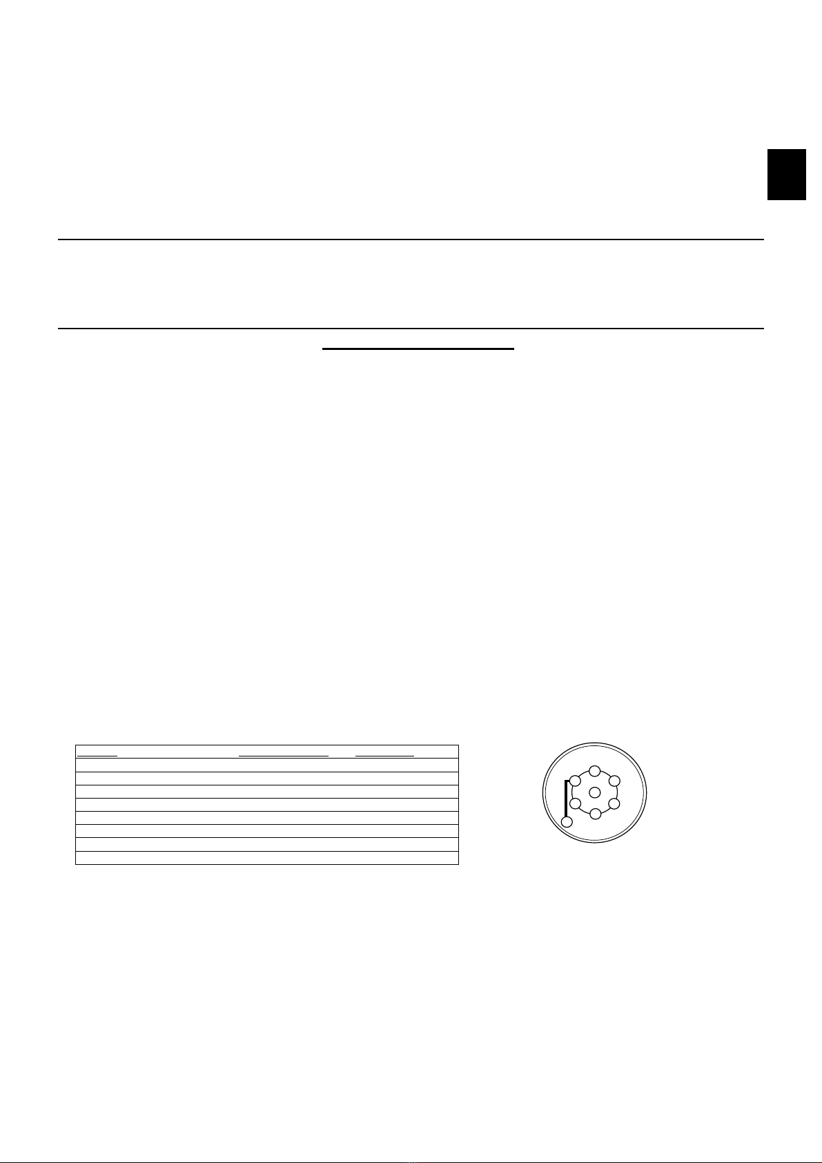
Kontaktbelegung:
1(L)
2 (54-G)
3 (31)
4(R)
5 (58-R)
6 (54)
7 (58L)
8 (58-b)
Bild 1
1
6
7
5
4
3
2
8
Kontaktbelegung
der Steckdose
6.
D

Das Leitungssatzende das mit einem Lgekennzeichnet ist, zur linken Rückleuchte verlegen.
a) Die fahrzeugseitige Steckverbindung 6-fach von der Rückleuchte abziehen und mit dem passenden
Gegenstück vom Leitungssatz zusammenstecken. Verbleibendes Steckgehäuse vom Leitungssatz auf
die Rückleuchte einstecken.
Die Leitungen braun an einen geeigneten Massepunkt anschließen. (ggf. 3 mm Loch bohren und mit
beiliegender Blechschraube befestigen. Bohrung nicht mit Korrosionsschutz behandeln)
Das beiliegende Modul auf das Steckgehäuse 8-fach des Leitungssatzes stecken und an geeigneter Stelle
mit Schraube M5x10 befestigen. Es ist besonders darauf zu achten, das keine Feuchtigkeit in das Modul
eindringen kann (Kurzschlußgefahr).
Die Leitung rot entlang der linken Fahrzeugseite in den Bereich der Zentralelektrik im Fußraum-Fahrerseite
verlegen.
a) Durchtrennen Sie in diesem Bereich an gut zugänglicher Stelle eine fahrzeugseitige Leitung mit der Funktion
Dauerplus-Klemme 30.
b) Die beiden Leitungsenden ca.5mm abisolieren, beileigende Steckhülse bzw. Flachstecker an die
Leitungsenden ancrimpen und in beiliegendes Steckhülsengehäuse bzw. Flachsteckgehäuse stecken.
c) An das Leitungssatzende rot den Sicherungshalter mit Sicherung und die 3-fach Anschlußleitung rot (kurz)
anschließen.
d) Die Stecker des Leitugssatzes mit den montierten Steckern der Dauerplus-Leitung verbinden.
Achtung!
Beim Anschluß der Leitung rot an eine fahrzeugseitige Dauerplus-Leitung auf
ausreichenden Leitungsquerschnitt achten ( Leitungsquerschnitt: 1.0 - 1.5 mm2).
Funktionshinweis Anhänger-Blinküberwachung:
Ein Defekt der Blinker des Anhängers wird im Anhängerbetrieb von der fahrzeugseitigen Kontrollleuchte über eine
Erhöhung der Blinkfrequenz angezeigt!!
Alle Leitungsstränge mit beiliegenden Kabelbindern befestigen, alle Verkleidungen und demontierten Teile wieder
einbauen.
Die Batterie wieder anschließen und sämtliche Fahrzeugfunktionen mit angeschlossenem Anhänger oder einem
geeignetenPrüfgerät überprüfen.
7.
8.
9.
10.
Electrical Set for Trailer Connection
7-pin
Renault Megane Hatchback
manufactured
. 03.99 - 10.02
Part no.:
WYR321207R
32 12 07R / 05.06.2019
Installation instruction
Disconnect the earth lead from the battery
Fold up the boot floor covering and remove the spare wheel. Dismantle the covering of both taillights in the boot.
Dismantle the sheathings on the left side of the boot and beneath the left side taillight.
To install the cable loom (socket connector), drill a 6mm Ø hole at a suitable place in the floor of the boot and
expand the hole to 20mm Ø. Treat the edges of the hole with a suitable anti-corrosive primer.
Connect the cable set in the following way:
a) Draw end of 7-conductor set of cables with metal terminals from boot thought the hole referred to in item 3
outside, then pull it through the hole in plug socket holder. Fasten initially assembled cable sleeve in the
aforementioned hole.
b) Draw attached rubber socket retaining plate over the end of cable set (if necessary use anti-friction agent),
c) Disassemble the socket and connect cables according to the following assignment:
1.
2.
3.
4.
Push the socket with rubber retaining plate and screw the socket tightly onto the retaining plate using the supplied
nuts and screws:
a) Pay special attention to the right position of rubber retaining plate,
b) Put the cable set gently to avoid any folds and to secure it from possible wiping.
5.
Packing list: 1 Cable set 1 Screws M5X10 1 Red connection wire 1 Socket contact bushing
1 Socket 13-pin 3 Screws M5X35 1 Sheet-metal screw 1 Flat plug bushing
1 Socket retaining plate 4 Spring washer 1 Fuse base 1 Socket contact
1 Rubber grommet 4 Nuts M5 1 Fuse 10A 1 Flat plug bushing
10 Cable ties 100 mm 1 Module UN-05
GB
Function
Indicator left
Fog light
Earth
Indicator right
Tail light right
Stop light
Tail light left
Fog light
Cable colour
black/white
grey
brown
black/green
grey/red
black/red
grey/black
grey/white
Contact description
1(L)
2 (54-G)
3 (31)
4(R)
5 (58-R)
6 (54)
7 (58-L)
8 (58-b)
Picture 1
1
6
7
5
4
3
2
8
Contact description in
7-pin socket

Lead the end of the wire loom marked Rto the right-hand taillight.
a) Pull the vehicle-side 6-pin socket housing off of the taillight and connect it with its counter piece of the cable
loom. Push the remaining socket housing of the cable loom onto the taillight.
Lead the end of the wire loom marked Lto the left-hand taillight.
a) Pull the vehicle-side 6-pin socket housing off of the taillight and connect it with its counter piece of the cable
loom. Push the remaining socket housing of the cable loom onto the taillight.
Attach the ring eyelets of the brown leads to a suitable ground point. (If necessary, drill a 3mm hole and attach the
eyelets with the supplied sheet metal screw. Do not treat the hole with anti-corrosive primer.)
Plug the supplied module onto the 8-pin socket of the wire loom and attach it at a suitable spot using the M5 x 10
screw and zip ties. Take extra care that moisture cannot enter the module (danger of short circuiting).
Lay the red lead forwards along the left side of the vehicle to the area of the central electrics box in the driver's side
foot well.
a) Cut a vehicle-side positive terminal +30 lead at an easily accessible spot in this area.
b) Strip the insulation of both ends for about 5mm, crimp the supplied flat connector and flat plug respectively
onto both ends and insert them into the flat connector housing resp. flat plug housing.
c) Connect the red end of the cable loom to the fuse holder with the fitted fuse and the triple red connecting
lead (short).
d) Connect the plugs of the cable loom with the newly fitted plugs of the permanent positive lead.
Attention!
When connecting the red lead to a vehicle-side permanent positive lead, make sure that this has a
sufficient cross section (1 - 1.5mm2).
Trailer lights control function
Faulty operation of trailer’s direction indicator is signalled by increased frequency of
flickering of vehicle’s indicators.
Secure the cable set with supplied cable ties, re-install all trims and other parts which were removed during
installation.
Connect the earth lead to the battery and check all vehicle functions with connected trailer or suitable testing
device.
Assembly instruction for the customer.
7.
8.
9.
10.
6.
Table of contents
Languages:
Other Trail-Tec Automobile Accessories manuals


Popular Automobile Accessories manuals by other brands

Whelen Engineering Company
Whelen Engineering Company Super-LED Traffic Advisor SC Series installation guide

GASLOCK
GASLOCK INDY-CATOR-DASH operating instructions

Belltech
Belltech 6640 installation instructions

Prorack
Prorack K105 Fitting instructions

Lemania Energy
Lemania Energy LE25.0 manual

Axxess
Axxess AXDIS-GMLN30 installation instructions

Porsche
Porsche Mobile Charger Connect installation manual

Hyundai
Hyundai K2F57 AC000 manual

Brink
Brink 6579 Fitting instructions

Code 3
Code 3 Thin SuperVisor MATRIX Series Installation and operation instructions

Volvo
Volvo R8902705 installation instructions

Rostra
Rostra UNIVERSAL SEAT HEATER installation instructions


