Trailer Vision Digi-View Mini User manual

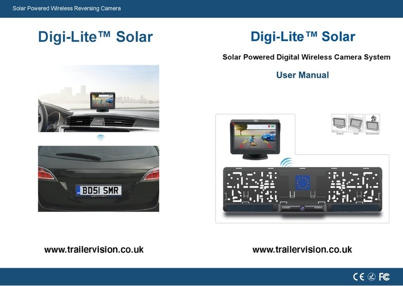
Digital Wireless Camera System
1
Digi-
V
ie
w
M
i
n
i
™

1 2
2. Monitor
Power Cable
Socket
Dashboard Mount
ADD
MENU/OK
DEC
Light Sensor
IR 'bulbs'
Antenna
Bracket
3. Additional Monitor
Mounts (included)
Vent Screw
4. Cigarette Lighter
Power Adapter
5. User Manual
6. Install Screws 7. Screwdriver (For Monitor Holder
& Vent Screw )
Cable
Thanks for purchasing Digi-View™ Mini.
Please read this User Manual before using/installing it.
Digi-View™ Mini is a Digital Wireless Camera system that can
display the view behind a vehicle/trailer etc. It can also be utilised to
view the inside of a trailer etc.
Digi-View™ Mini utilises 2.4Ghz digital wireless transmission, is
powered by the vehicle/trailer and therefore does not require a
cable between the camera and monitor (ideal for trailer
applications).
The system and User Manual may be updated at any time.
Trailer Vision Ltd reserve the right to modify and update the system
specifications/functionality without prior notice.
4.3” Screen
COMPONENTS
01.
9
10
Specification
6
Camera Installation 3
9
Monitor Mount
03 4
07
Buttons & Setting
Disclaimer
Warranty Info
Contents:
1.Camera
Windscreen
Mount
Air Vent
Mount

34
CAMERA INSTALLATION
Power Negative
Power Positive “+”
1. Use the supplied screws to fix the camera to the vehicle.
2.
Connect the camera power cable to the vehicle power system (lights etc).
90°
90°
Light Sensor
IR
'Lights'
IR 'Lights' (Night Vision)
The light sensor underneath the camera lens
detects light changes and will automatically turn
on the IR 'lights' at night, or in low light conditions,
so that the image is clearer (B&W image).
Plug & Play
Notice:
Before rotating the camera, loosen the fixing screw on the
side of the camera, hold the camera with one hand, rotate
it up or down, and tighten the screw after reaching the
best angle.
3. Connect the power cable to the monitor & insert the
cigarette lighter power adapter into the vehicle's
adapter socket. Switch the monitor on and then
adjust the camera angle to the ideal viewing
position, then fix it by tightening the bracket screws.
Cigarette Lighter Socket
1. The monitor can be fixed to the dashboard, windscreen or
air-vent.
2. How to install the mounts:
1) The dashboard mount is already attached
to the monitor and can be stuck to the dash
board. Choose and clean a suitable location
on the dashboard, remove the paper from the
monitor stand sticky pad and firmly press the
stand mount onto the dashboard.
2)
If using the windscreen mount, please
replace the dashboard mount by utilising
the supplied screwdriver.
03.
Used for reversing assistance For in-vehicle monitoring
Dashboard Mount Air Vent Mount WIndscreen Mount
MONITOR INSTALLATION

Choose a suitable place on the windscreen and mount the suction cup
;
with the suction lever in
the released position, press the suction cup
against the windscreen. Press the suction
lever toward the suction cup to lock the
mount. To adjust the angle of the monitor, loosen
the collar on the ball joint & retighten in the
desired position.
3. Connect the monitor to vehicle power via the cigarette lighter
power adapter.
56
Rotating the image and switching between 'normal' and mirror image
view:
When the monitor is displaying the camera image short press [MENU/OK]
to enter the main menu interface, select the "Image Mirror" icon and long
press [MENU/OK], to set 'upwards' or 'downwards' image. After setting,
short press twice to exit the setting.
Select the "Image Mirror" icon and long press the middle button [MENU/OK]
to enter the mirror setting interface, short press [ADD] or [DEC] button to
set mirror or normal image. After setting short press [MENU/OK] twice to
save and exit.
NB. Please use mirror image (default view) for reversing and rear view
applications.
04.
3) If utilising the air-vent mount, please remove the
dashboard mount and complete the following instructions:
Use the L-shaped screwdriver
to tighten the vent screw
Make sure that the cross of the
base lines up with the cross on
the rear of the monitor
Insert the ball into the nut
Rotate the nut and tighten
clockwise
Press the vent mount ball
firmly into the threaded base
Move the lever up/down to
clamp to the vent
BUTTONS & SETTINGS
Function of the rear buttons:

7 8
Parking guidelines displayed or not displayed:
Short Press DOWN button [DEC] to switch between the Parking Guide
Lines display modes (Displayed or Not Displayed):
While the monitor is showing the image, short press the middle button
[MENU/OK] to enter the main menu interface, and 5 options are available
(Pairing, Image Parameters, Image Mirror, Parking Guideline Position
Adjustment & Software Information).
Pairing Image
Parameter
Image
Mirror
Software
Information
Parking Guideline
Position Adjustment
Operation
Pairing Image
Parameter
Image
Mirror
Parking Guideline
Position Adjustment
Software
Information
Default setting,
no need to
operate again.
To adjust Brightness
Contrast, Colour.
Operation details
as Image Parameter
info.
Set Upwards/Downwards
or Normal/Mirror Image.
Operation details as
Image Mirror contents.
Select “Software Info”,
press [ADD] or [DEC]
key to display software
version information.
The parking guideline can
be adjusted up and down
as needed. Operation details
as Parking Guideline Position
Adjust info.
5 levels of adjustment
Parking Guideline Position Adjustment
The parking guideline position can be adjusted
up or down, to mark the image area more realistically.
There are 5 levels to choose from.
For detailed operation methods,
please refer to page P8.
Select the Brightness icon, press
[ADD] or [DEC] button to adjust the
brightness as shown bellow:
Select the Contract icon, press
[ADD] or [DEC] button to adjust the
contract as shown bellow:
Select the Colour icon, press
[ADD] or [DEC] button to adjust
the colour as shown bellow:
Brightness Contrast Color
2. Image Parameter
While the monitor is showing an image, short press the middle button
[MENU/OK] to enter the main menu interface. From the 3 options.
Select Image Parameter, long press the [MENU/OK] button again,
3 Images(Brightness/ Contrast/ Color) setting interface are shown bellow:
3. Parking Guideline Position Adjustment
Select the “Parking Guide Position Adjustment” icon, then long press the middle
button [MENU / OK] to enter the setting interface, short press the [ADD] or [DEC]
button to choose the most suitable one from 5 levels, then short press [MENU / OK]
twice to exit.
A B C D E
Brightness Setting
Contrast Setting
Colour Setting

05.
9 10
Input Power Voltage: DC 9V-30V
Input Power Voltage (Cigarette lighter): DC 9V-30V
06. DISCLAIMER
This Digital Wireless Camera system is intended to assist the driver, but it
doesn't relieve the driver from full responsibility for operation of the vehicle. It
is the driver's sole responsibility to drive safely, legally and responsibly. By
installing and/or using this Digital Wireless Camera system, you agree that you
are solely responsible for the operation of your vehicle, the system Supplier is
not responsible for any property damage, personal injury, or loss of life that
may result from the operation of your vehicle.
WARRANTY:
BE SURE TO KEEP A COPY OF YOUR SALES RECEIPT!
STANDARD WARRANTY
Trailer Vision Ltd warranty that your NEW Product is free of defects of
workmanship and materials. If there is a defect or malfunction of this product,
Trailer Vision Ltd will repair/replace it free of charge, as follows:
ONE YEAR from date of purchase.
(Any faulty items may be required to be returned for test/replacement).
For support or warranty claims please contact:
01733 246473
07. WARRANTY INFO
This warranty does not apply to persons who purchased this product
second-hand or used.
This warranty does not include adjustments, parts and/or repairs required by
circumstances beyond the control of Trailer Vision Ltd, including but not
limited to fire or other casualty, accident, neglect, abuse, misuse, abnormal
use or battery leakage damages.
THERE ARE NO OTHER EXPRESSED WARRANTIES EXCEPT AS
STATED HEREIN. AFTER THE PERIOD OF EXPRESSED WARRANTY SET
FORTH HEREIN, THERE ARE NO EXPRESSED OR IMPLIED
WARRANTIES AND THOSE EXCLUDED INCLUDE THOSE OF
MERCHANTABILITY AND FITNESS FOR PARTICULAR PURPOSE. Trailer
Vision Ltd shall NOT be held
liable for any CONSEQUENTIAL DAMAGES
resulting from any failure, defect or malfunction of this product. Some
Regions do not allow limitations on how long an implied warranty lasts and
some Regions do not allow the exclusion or limitation of incidental or
consequential damages, so the above limitations may not apply to you.
Effective Transmission Distance: Up to 30m (line of sight)
Table of contents
Other Trailer Vision Car Video System manuals
Popular Car Video System manuals by other brands

Lexus
Lexus IS 250 2014 Navi owner's manual
Pyle view
Pyle view PLRD195IF operating instructions
Setma
Setma E09UN00009 installation manual
Kustom Signals
Kustom Signals Digital Eyewitness HD installation manual
Speedsignal
Speedsignal Elw-Tec B-360AD01 installation guide
Hyundai
Hyundai 2012 Genesis Quick reference guide
