ADS-RR(SR)-HON02-DS maestro.idatalink.com
honda accoRd cRosstouR
Automotive Data Solutions Inc. © 2018 3
INSTALLATION INSTRUCTIONS
STEP 1
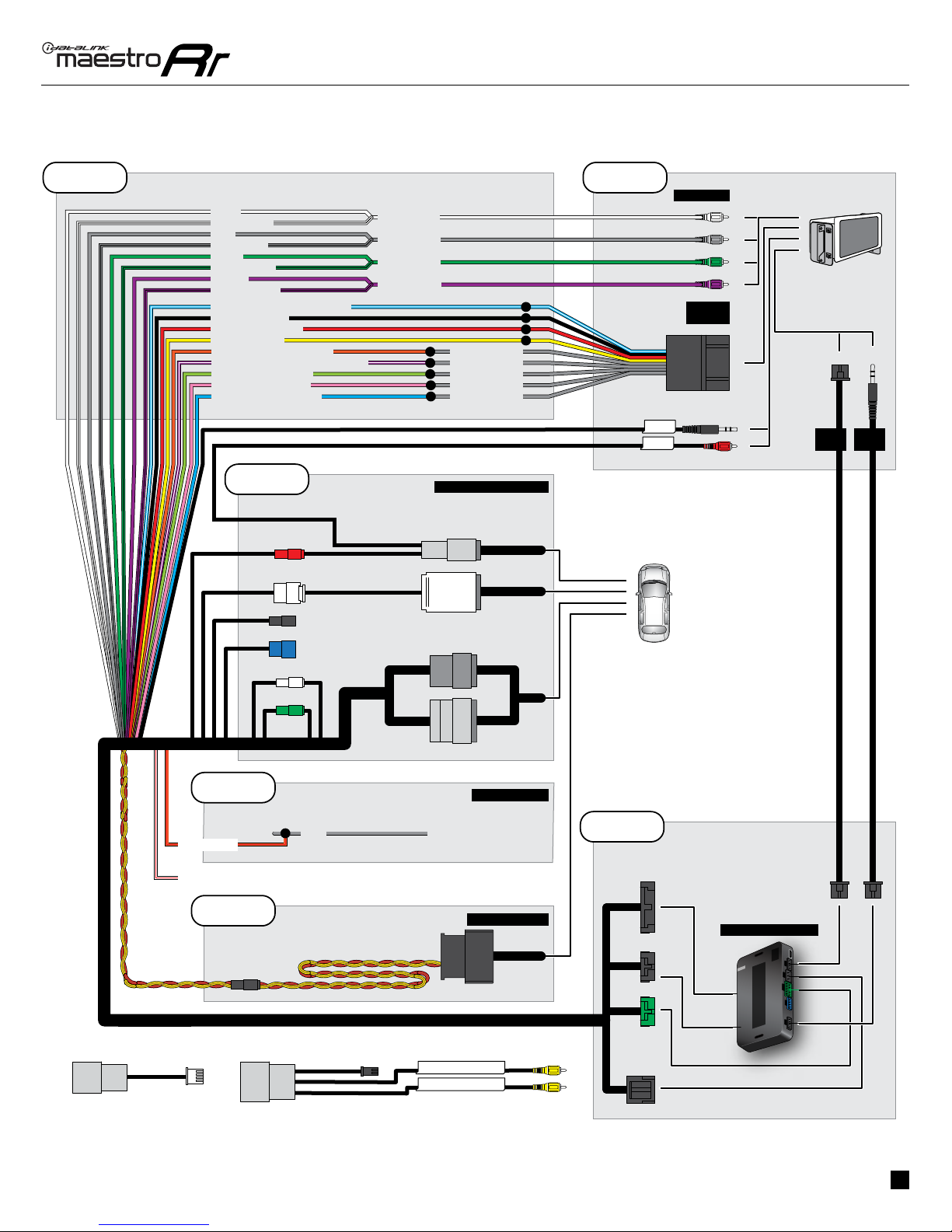
• Unbox the aftermarket radio and locate its main harness.
• Connect the wires from aftermarket radio main harness to
the HO2 T-harness and match the wire functions.
• Remove the factory radio.
STEP 2
• Assemble the HO2 T-harness and connect it to the factory
radio harness.
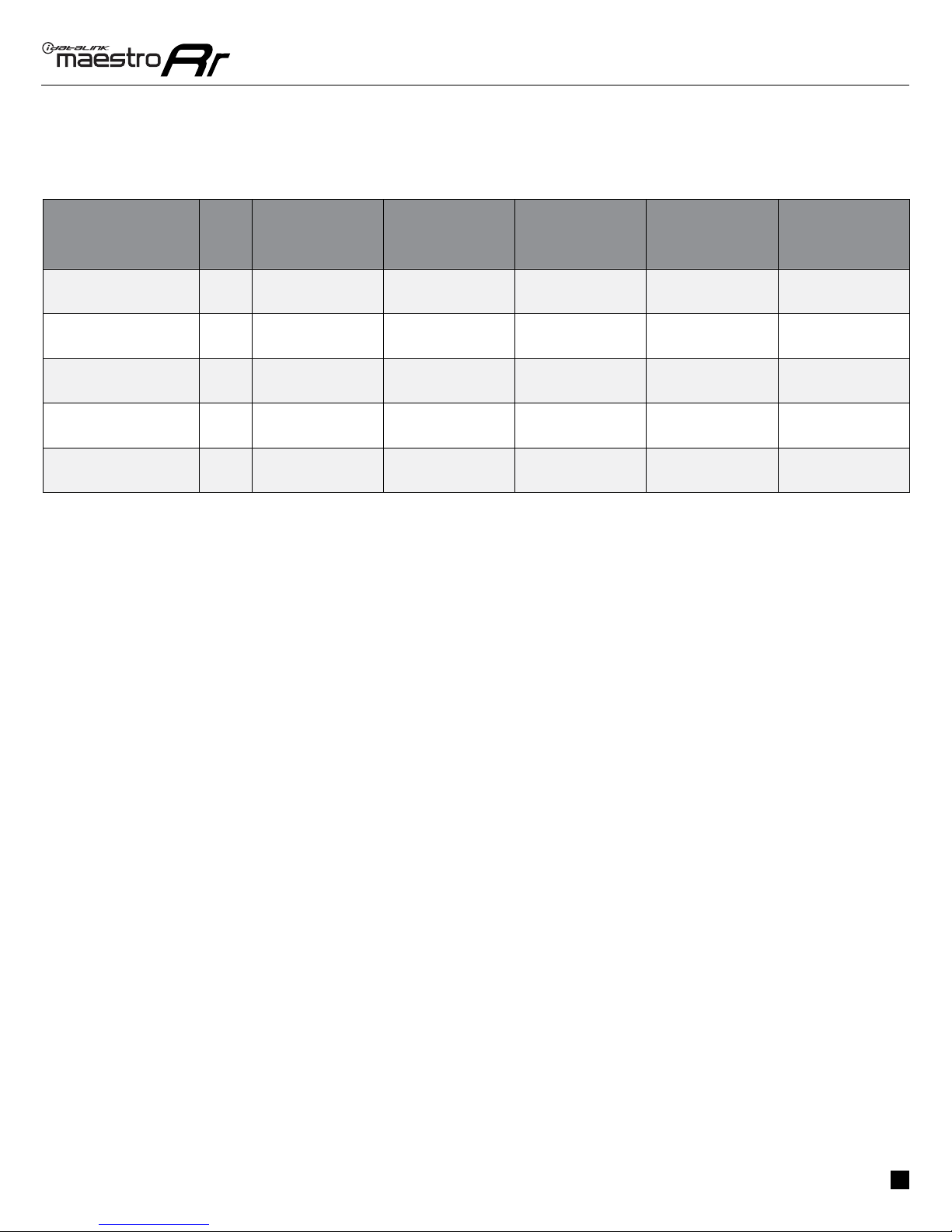
• If the vehicle is equipped with a backup camera in the MID,
see the vehicle wire reference chart for wiring information.
STEP 3
• Connect the Orange/Red wire at the Bluetooth module. See
the vehicle wire reference chart for wire color and location.
STEP 4
• Plug the OBDII connector into the OBDII of the vehicle,
under driver dash.
STEP 5
• Plug the aftermarket radio harnesses into the aftermarket
radio.
• Connect the speakers and sub RCA cables.
• Plug the AUX cable to the aftermarket radio (if the vehicle
is equipped with an OEM aux port).
• Plug the Data cable to the data port of the aftermarket
radio.
• Insert the Audio cable into the iDatalink 3.5 mm audio jack
of the aftermarket radio.
Note : When using a Pioneer or Alpine radio, the audio cable
will plug into the AUX port.
STEP 6
• Connect all the harnesses to the Maestro RR module then
test your installation.
TROUBLESHOOTING TIPS:
• To reset the module back its factory settings, turn the key
to the OFF position then disconnect all connectors from
the module. Press and hold the module’s programming
button and connect all the connectors back to the module.
Wait, the module’s LED will flash RED rapidly (this may
take up to 10 seconds). Release the programming button.
Wait, the LED will turn solid GREEN for 2 seconds.
• For technical assistance call 1-866-427-2999 or e-mail
com/support” and “www.12voltdata.com/forum/”
8