Trakm8 T8 User manual

T8 Mini Installation Manual
T8-Mini & Derivatives
For Cars, Car Derived Vans,
Light Commercial Vehicles
Heavy Goods Vehicles and Trailers

T8-Mini Installation otes v1.0
Generic T8-Mini Installation otes v1.0.doc
Page 2
1 Table of Contents
1
Table of Contents 2
2
Contact Information 3
3
Document Revision History 4
4
Preface 5
4.1
Safety Information 5
4.2
pproval Information 6
4.2.1
Production Test 6
Installation Information 6
4.3
Important Notes! 6
5
Installation 7
5.1
Recommended Installation Sequence Summary 8
5.2
SIM Card 8
5.2.1
Before fitting the SIM card 8
5.2.2
Fitting the SIM card 9
5.3
Mounting the T8-Mini 10
5.4
T8 Wiring and Connections 10
5.4.1
Cable and ccessory Wiring Options 11
5.4.2
Internal GSM/GPS Antenna 11
5.4.3
Power Ground and Ignition Installation 12
5.4.4
Driver Interface Button (Optional) 13
5.4.5
Driver ID Dallas Interface (Optional) 13
5.4.6
Digital Inputs/ nalog Inputs/Digital Outputs 13
5.4.7
T8-Mini Immobiliser Feature. 15
6
Testing 16
6.1
Engineering Mode 16
6.2
Server data 18
7
Appendix A –T8-Mini Wiring iagram 19
8
Appendix B –T8-Mini Connections & Ratings 20
9
Appendix C –T8-Mini-GPRS Records 21

T8-Mini Installation otes v1.0
Generic T8-Mini Installation otes v1.0.doc
Page 3
2 Contact Information
All initial communication or enquiries should be made to:
Trakm8 Limited
Lydden House
Wincombe Business Park
Shaftesbury
Dorset
SP7 9QJ
UK
International Tel: +44 (0) 1747 858444
International Fax: +44 (0) 1747 858222
Orders Order @trakm8.com

T8-Mini Installation otes v1.0
Generic T8-Mini Installation otes v1.0.doc
Page 4
3 Document Revision History
Document Issue Date of Issue Reason/Description of change
1.0 Draft 25-03-11 Fir t Draft
1.0 20-02-12 Fir t relea e

T8-Mini Installation otes v1.0
Generic T8-Mini Installation otes v1.0.doc
Page 5
4 Preface
Failure to comply with the following Warnings, pproval and Safety
information may invalidate warranty, certification or type approval of this
product.
1. ever operate the T8-Mini Platform in close proximity to the human body.
W RNING!
Current FCC regulations limit the EIRP of mobile devices to 2 W.
20 cm (7.87 inch) separation distance between the unit and all
persons must be maintained at all times.
2. Unauthorised modification to this equipment or associated accessories is
forbidden without the express permission and agreement from the product
manufacturer.
3. This equipment should not be operated in hazardous environments i.e. areas
that contain explosive materials or flammable vapours.
4. This equipment should not be operated within aircraft or in close proximity to
medical equipment.
5. Internal components containing beryllium oxide may be used in this
equipment. Dust from this material is a health hazard if inhaled or allowed to
come into contact with the skin. Great care must be taken when handling
these components.
4.1 Safety Information
Please adhere to the following Safety and Installation information at all times.
Supply Voltage: +8V minimum to +32V maximum
Current consumption at: 12V <= 45mA – fit a 2A inline fuse.
24V <= 25mA – fit a 2A inline fuse.
Battery charging peak < 500mA at 12V.
ote: Fuses should be placed in all power lines as close as possible to the
vehicle supply source. (Supply fuse: 2A, Ignition Fuse: 1A)
THE RATINGS OF THESE FUSES SHOUL NOT BE EXCEE E AT ANY TIME
WARNING!
This equipment may only be located in a position where it cannot interfere
with the normal operation of the vehicle or present a hazard to the driver or
passengers. Care must also be taken in the routing of all cables so that the
insulation does not become worn or damaged.

T8-Mini Installation otes v1.0
Generic T8-Mini Installation otes v1.0.doc
Page 6
4.2 pproval Information
The product can be marketed worldwide. Therefore the following certifications
and approvals are provided.
CE –marking
“e” –marking
R&TTE 1999/5/EC (EN3014891) and EN60950-1:2001
FCC
PTCRB registration
The product conforms to CE-marking and e- marking. It is certified with tests
according to R&TTE 1999/5/EC, E 301489-1 and E 60950-1: 2001 for CE
conformity and according to EMV 2004/104/EG for e conformity, respectively.
4.2.1 Production Test
Each module is 100% tested prior to packing and shipping.
Installation Information
All installation and service work must be carried out in accordance with MPT
1362, MPT 1372, RQAS, and VSIB, 95/54/EC, ISO 21609 and / or any other
statutory guidelines or Directives currently in force.
Therefore it is strongly recommended that the T8-Mini platform is installed and
commissioned by suitably trained and qualified Installation Personnel i.e. in the
UK those who are accredited and registered by the Vehicle Systems Installation
Board (www.vsib.co.uk). This is essential in order to maximise any Insurance
discounts that may apply.
4.3 Important Notes!
1. Unauthorised changes or alterations to the equipment or the installation will
invalidate certification issued by the Approved Accreditation Bodies and may
also affect the vehicle manufacturers warranty.
2. Under no circumstances may any part of the T8-Mini system be installed
inside the engine compartment area.
3. The T8-Mini platform contains devices that are susceptible to static damage.
It is necessary to use a proprietary anti-static (ESD) workstation prior to, and
whenever the cover is removed from the unit for service & commissioning
purposes.
4. Where the T8-Mini platform is to be installed into a company vehicle, all
employees or other individuals who are authorized to drive that vehicle
should be advised that a tracking unit is installed, in order to limit any
potential risk of privacy and employment law issues. It is strongly
recommended that evidential proof of this advice be sought and retained.

T8-Mini Installation otes v1.0
Generic T8-Mini Installation otes v1.0.doc
Page 7
5 Installation
Before you begin installing and commissioning the system please ensure that
you have read this manual thoroughly referring to any supplementary information
provided for the T8-Mini as required.
This document covers the T8-Mini and its connections through the following
process:
1. Recommended Sequence
2. Fitting the SIM
3. Mounting the Unit
4. Wiring and connections
i. Power, Ground and Ignition
ii. Internal GSM/GPS Antenna’s
iii. Driver Interface Button/LED
iv. Dallas i-Button/LED
v. Inputs
vi. Outputs
Some of the items above are optional and you may ignore sections describing
features that your T8-Mini does not have.
Important Notes!
When using the T8-Mini you should remember the following:
1. In order for GPS to function correctly, the unit must have a clear view of
the sky in order to receive data from the satellites. Should this view be
obscured, e.g. the vehicle is parked in a metal-clad building then the
performance of the T8-Mini platform may be impeded. Wherever possible
it is preferable to park the vehicle in a location where the antenna will have
a clear all round view of the sky.
2. Whenever you disconnect the T8-Mini from the power supply it may lose
its stored data and so may take a while to obtain a GPS fix when you plug
it back in. The T8-Mini may also lose certain other information from its
memory particularly if the optional backup battery is not fitted. Please
ensure that you take this into consideration when having the vehicle
serviced, as the vehicle battery connections are often removed during
some service procedures. Tell the service technician that you have a T8-
Mini fitted and request that if possible they use a “vehicle memory saver”
plugged into the cigarette lighter socket – this type of device will support

T8-Mini Installation otes v1.0
Generic T8-Mini Installation otes v1.0.doc
Page 8
both the T8-Mini and your vehicle radio system whilst the vehicle battery
is removed.
WARNINGS
1. Do not smoke or use open flames when working near the vehicle.
2.
Ensure that the vehicle’s electrical cables, hydraulic lines, fuel lines, and
safety equipment are not damaged during the installation
.
3.
Ensure that normal control and operation of the vehicle is not impaired by
the installation, particularly the brakes and steering. Ensure that the
airbag operation is not obstructed
.
5.1 Recommended Installation Sequence Summary
The following installation sequence is recommended. Please refer to the detailed
instructions elsewhere in this document for further details.
1. Plan the whole installation and determine suitable locations, mounting
arrangements and cable routes for all hardware items.
2. Fit SIM card (if not supplied pre-installed). Please note that the SIM must be
inserted correctly and the SIM PI code removed where necessary using a
mobile phone.
3. Connect internal back-up battery if fitted to the T8-Mini.
4. Temporarily mount the main T8-Mini and wire the Power and Ignition Sense
feeds leaving the in-line fuses out.
5. Check for optimum location of the GPS unit for GPS signal detection using
the engineering modes. The unit will need to be powered up by temporarily
fitting the fuses.
6. Permanently mount the main T8-Mini in its optimum location.
7. Fit the fuses for the T8-Mini.
8. Commission and test the system.
5.2 SIM Card
5.2.1 Before fitting the SIM card
1. If you have not already registered your SIM card with the mobile network, you
should do this before proceeding. Please refer to the appropriate mobile
network operator instructions on how you do this.
2. Make a note of the number on the SIM card (ES ) as well as a note of your
Voice & Data telephone numbers. There is a convenient space in ppendix
B – T8-Mini Records where you can record this information.
3.
Ensure that a PI number does not protect the SIM card. If this is the case, it
must be removed before inserting it into the T8-Mini – this can be done by

T8-Mini Installation otes v1.0
Generic T8-Mini Installation otes v1.0.doc
Page 9
inserting the SIM into a suitable mobile telephone and then following your
mobile telephone instruction booklet
.
5.2.2 Fitting the SIM card
Important Note!
When inserting or removing the SIM card from the T8-Mini it is necessary to take
the necessary anti-static (ESD) precautions in order to prevent damage to the
unit, these precautions should also be employed prior to removing the cover from
the unit at any time for service and commissioning purposes.
1. Remove the base of the T8 Mini by flexing the latching lugs on each side in
an outward manner to release it from the main body assembly. This is best
achieved using the leverage tool provided or two medium size flat blade
screw drivers in tandem.
2. Relea e the SIM cradle by liding the ilver locking bar toward the GSM
Antenna and allow it to tilt away from the circuit board. Slide the SIM card
into the lot of the tilting ection, o that the gold contact on the SIM card
are facing downward toward the circuit board and that the traight edge of
the SIM card i in erted fir t toward the hinge.
SIM card
holder
Battery
connector
Internal GSM
Antenna
Main M12
connector

T8-Mini Installation otes v1.0
Generic T8-Mini Installation otes v1.0.doc
Page 10
3. Ensure that the SIM card and cradle are pressed gently towards the circuit
board so that it sits flat and slide the silver latching bar away from the GSM
Antenna to lock it in place.
4. Replace the base of the unit by compressing the two halves firmly together
against the seal until the latching lugs click into place.
5.3 Mounting the T8-Mini
You may choose to mount the T8-mini somewhere covertly e.g. in the boot,
under the parcel-shelf or under the dashboard. Suitable mechanical fixings must
be used (not supplied). If the on-board Accelerometer is to be used then it is
extremely important that the unit is rigidly mounted such that it cannot move.
WARNINGS:
1. Your T8-Mini must be securely mounted in a location where it cannot
interfere with the normal operation of the vehicle. It must OT be located in a
position where the cables or the Unit become a hazard to the driver or
passengers.
2. The T8-Mini has been designed with an IP rating of IP67 and as such can be
located in splash areas within the vehicle. Having said this it is recommended
that the unit is not installed inside the engine compartment or areas where it
may come into regular contact with fluids and corrosive substances.
5.4 T8 Wiring and Connections
Important Notes!
1. Unauthorised changes or alterations to the equipment or the installation will
invalidate certification issued by the Approved Accreditation Body and could
also affect the vehicle manufacturer’s warranty.
2. The notes below should be read in conjunction with fig.1 –T8 Mini Wiring
Diagrams.
3. All wiring should be professionally connected to the vehicle electrics via
soldered connections using automotive grade fuse holders and fuses. In
situations where the soldered connections are prohibited by the vehicle
manufacturer and or the customer then AD-Link fuses may be used to pick up
the appropriate Power and Ignition supplies.
4. All wiring should be safely secured to avoid damage from, or chaffing by, any
hot or moving parts.
5. Position the wiring carefully to avoid the possibility of snagging or impact
damage during the normal use of the vehicle.

T8-Mini Installation otes v1.0
Generic T8-Mini Installation otes v1.0.doc
Page 11
6. Before any holes are drilled, check that no parts, wires, pipes or tanks could
be damaged at the exit point of the hole. Suitable grommets must be used
where wires are routed through body panels to prevent chaffing and short
circuits to the chassis.
7. Leave the fuses out of their holders until the installation is complete.
5.4.1 Cable and ccessory Wiring Options
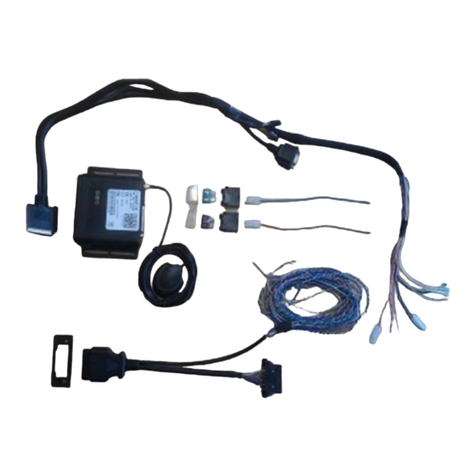
The T8-Mini platform i provided with a ingle cable and doe not have any plug
and play acce orie at thi tage.
However the following ection will include pecific reference a to how to wire
up variou acce orie to deliver the functionality of the firmware.
The electrical connection for the current functionality can be found in the wiring
diagram in Appendix A.
5.4.2 Internal GSM/GPS Antenna
The T8 Mini contains an internal GSM antenna and an internal GPS antenna and
therefore the location of the unit is important to optimise the performance. The
unit should be positioned horizontally and located in a position where it will have
an unobstructed view of the sky. The ideal location in most cars is in the centre
top of the dashboard or behind the instrument cluster as far forward in the vehicle
as possible with the top of the unit facing skywards.
OTE
The GSM antenna is now internal to the unit so care must be taken as to where
the unit is mounted.
Important ote!
The performance of the equipment may be impeded if the unit is mounted
beneath or in very close proximity to electrically conductive materials,
such as metal, certain types of plastic, metalized film or laminate
windscreens. If this applies to your vehicle please install the antenna and
unit elsewhere.
20 cm (7.87 inch) separation distance between the unit and all persons
must be maintained at all times.
When you commission the T8-Mini you will be able to carry out tests to
determine whether suitable GSM and GPS signals are being received. If in doubt
about the suitability of your planned location, it is recommended that you only
temporarily install the unit until you are able to carry out the appropriate
engineering tests. (See Section 5 – Engineering Mode)

T8-Mini Installation otes v1.0
Generic T8-Mini Installation otes v1.0.doc
Page 12
5.4.3 Power Ground and Ignition Installation
Below i a wiring block diagram of the T8 Mini y tem which will be covered in
detail within the following ection .
There i ONLY a ingle cable a embly upplied with the T8-Mini unit and
con i t of a traight 8 pin M-12 connector with un-terminated end (CAB050).
This cable consists of an 8 pin M-12 connector and determines the functionality
that is available to the user. Regardless of which cable is used the Power,
Ground and Ignition connections are identical and should be wired as follows.
Wire
Colour
Description Notes
Red Vehicle Supply
Positive (+ve)
Connect to a permanent Positive supply (8 to 32V) via a 2
amp in-line fuse.
Brown Vehicle Supply
egative (-ve)
Connect to permanent egative supply.
Blue Ignition Sense
Positive (+ve)
switched (active
high)
Connect to a switched ignition line via a 1 amp in-line
fuse. This ignition line should be a true engine running
signal to ensure that journeys are detected correctly. This
must be a primary or “D circuit” connection. An auxiliary
ignition connection is NOT acceptable as this will result in
incorrect operation of the product.
It is highly desirable that these connections are soldered to ensure a good
permanent connection to the vehicle supply and ignition points. It is not the
intention of this manual to cover all electrical connection points for all vehicle
types and therefore the experience of qualified fitting staff is essential to ensure
that suitable location points are found for the vehicle in question. Alternatively
Ad-Link connections connected to the fuse board of the vehicle can be used if a
on Invasive installation is required. For further information on Ad-Link fuses
please E-mail [email protected] for further information.
It is strongly recommended that power pick up points are chosen that DO OT
form part of an auxiliary supply such as cigar lighter or auxiliary power sockets as
these can be compromised by the connectivity of third party devices such as
power chargers, invertors, tools etc.

T8-Mini Installation otes v1.0
Generic T8-Mini Installation otes v1.0.doc
Page 13
5.4.4 Driver Interface Button (Optional)
The T8-mini provides a single wire interface that can be used for the driver
interface button and/ this is also multiplexed as a bidirectional Dallas 1-wire
interface. (See section below)
In order to use this pin as driver button simply connect a switch between this pin
and ground as shown in the wiring diagram in Appendix A. If the Driver button is
fitted with an LED for use as business/Private indication then the LED will also
need to be wired as shown in the diagram.
5.4.5 Driver ID Dallas Interface (Optional)
The T8-mini also implements the required driving circuitry to use this pin as a
Dallas 1-wire interface. This allows an easier implementation of the 1-wire
protocol.
5.4.6 Digital Inputs/ nalog Inputs/Digital Outputs
The T8-Mini O LY has two I/O pins available on the M12 connector. These two
pins (3, Pink = I/O 0) (7,Green = I/O 1) can be used for digital inputs/ analog
inputs or as outputs. If the user is operating the product with the Trakm8
application then both of these I/O have been defined as Outputs to operate the
Red LED and Immobilizer functions.
5.4.6.1 Digital Inputs
All of the T8 Mini inputs (including the ignition) have the same specification and
are capable of detecting a signal from 0v to +32v. The input is deemed to have
“GONE HIGH” when the voltage is greater than 5v and “GONE LOW” when the
voltage is less than 2v (including the open circuit state see below).
Therefore the connection of an input wire into a vehicle circuit varies depending
on the voltage of the circuit being monitored and the direction of state change
you are monitoring for.
In the open circuit state all T8 Mini input circuits are in the low state and therefore
careful consideration must be given when wiring up the input to ensure the
change of state produces the required trigger you are after especially if you want
to detect both the “GOES HIGH” and “GOES LOW” state change.

T8-Mini Installation otes v1.0
Generic T8-Mini Installation otes v1.0.doc
Page 14
Below are some examples of monitoring circuit state changes.
Signal Transition from 0V to +12v/+24v
If the input monitoring is a signal or switch circuit that is producing the actual
voltage transition then the input wire can be connected directly to the circuit and
it should be possible to detect both state transitions.
Signal Transition from open circuit to +12v/+24v
If the input monitoring requires the detection of a switch closing to supply
(+12v/+24v) then the input is simply wired to the normally open side the switch.
Signal Transition from >5v to +12v/+24v
If the input monitoring requires the detection of a voltage change that does not
transition below 2v then a potential divider is required to drop the lower voltage
state into the triggering region. To keep the current drain to a minimum the
combined resistance value should be greater than 10K to keep the current below
1mA.
Signal Transition from open circuit to 0V
If the input monitoring requires the detection of both state transitions of a switch
switching from open circuit to ground, then a pull up resistor is required to
generate the “GOES HIGH” state when the switch becomes open circuit. Again
the resistor value should be greater than 10K to keep the current drain to a
minimum when the circuit is closed.
5.4.6.2 nalogue Inputs
The T8 Mini input are capable of being configured a Analogue input with a 12
bit re olution. Thi i currently not implemented in the Trakm8 application.
5.4.6.3 Digital Outputs
The T8-Mini I/O is capable of being configured as outputs. The outputs are
automotive grade open collector FET devices that drive the output to ground
when active. The FET is capable of sinking up to 500mA and is therefore suitable
for driving lamps, buzzers and relays as required.
The Trakm8 application is currently using these to drive the Red Led and the
immobiliser functions implemented in the T8.

T8-Mini Installation otes v1.0
Generic T8-Mini Installation otes v1.0.doc
Page 15
5.4.7 T8-Mini Immobiliser Feature.
Important Notes!
1. Unless local law permits the T8-Mini Immobiliser MUST NOT be connected
in such a way that it would be possible to disable the vehicle whilst it is under
way. The immobiliser must be wired in such a way that it is only breaking a
cranking circuit of the vehicle. Careful consideration must be observed when
choosing this circuit as modern vehicles usually have these types of circuit
monitored by the ECU of the vehicle. This could lead to a malfunction of the
vehicle’s own monitoring system and may invalidate the manufacturer’s
warranty if the correct circuit is not chosen. (If in doubt then please contact
the vehicle manufacturer for advice).
2. When the Immobiliser is driven in all modes other than “OTA” the T8 Mini is
enabling the relay and utilising the normally open contacts of the relay to un-
immobilise the vehicle. Therefore if the main power and internal battery
backup are removed, then the T8-Mini Immobiliser will default secure so as
to render the vehicle immobilised
3. When the immobiliser is driven in In “OTA” mode of operation the T8 Mini is
enabling the relay and utilising the normally closed contacts of the relay to
immobilise the vehicle. Therefore when it is in the unpowered state the T8-
Mini Immobiliser is inactive and the vehicle will always start.
(See the wiring diagram in Appendix A).
The output of the T8-Mini consists of an Open collector FET capable of sinking
up to 500mA.
This is more than adequate to drive an automotive grade relay. The diagram in
Appendix A shows a normally open relay being driven being driven by output 0
(m12 pin 3).
If modes other than “OTA” are used then the normally open set of contacts
(30/87) are used.
If “OTA” mode is being used then the normally closed set of contacts (30/87a)
are used.

T8-Mini Installation otes v1.0
Generic T8-Mini Installation otes v1.0.doc
Page 16
6 Testing
Once installed the equipment should be tested to ensure that it is operating
satisfactorily and that the positions of the installed items do not impair the driver’s
ability to control and operate the vehicle in any way.
The T8 Mini does not contain any visual indicators on the case such that it does
OT impact on its IP67 rating. Therefore the only means a fitter has of testing
the T8 Mini is to use the engineering screens in the firmware and liaise with the
commissioning team as to the integrity of the data being sent to the server. The
fitter will need to make up a test lead, following the information given in Appendix
A such that the driver button and LED can be used for engineering Mode” testing.
If this is OT done then the only means for testing is through the commissioning
team and the server data integrity.
6.1
6.16.1
6.1 Engineering Mode
Engineering ModeEngineering Mode
Engineering Mode
The T8 has an engineering mode to assist installation and test engineers out in
the field. Engineering Mode is entered by pressing the driver id button >10
times or by issuing the SETE G command. The led will come on solid for a
short period indicating that it is in engineering mode. It will then flash once
indicating that it is in screen one. Subsequent single presses of the button will
advance the engineering mode through the other engineering screens. Upon
entering each engineering screen the led will flash the appropriate number of
times indicative of the screen number you have just entered.
Pressing the button >10 times (but less than 20) will exit the engineering mode.
Engineering screen 1 (GSM/GPRS/GPS indication)
0 trill = no network coverage
1 trill = GSM ok
2 trill = GSM & GPRS ok
3 trill = GSM, GPRS & Jabber connection connected ok
And
0 flash = o GPS coverage
1 flash = 1 satellite, time fix possible
2 flash = 2D GPS fix
3 flash = 3D GPS fix
Engineering screen 2 (Ignition detection)
Led On Ignition On
Led Off Ignition Off

T8-Mini Installation otes v1.0
Generic T8-Mini Installation otes v1.0.doc
Page 17
Engineering screen 3 (External power detection)
You must have the internal Battery connected for this screen to operate
correctly
Led On Ext Power present
Led Off Ext power absent
Engineering screen 4 (Internal Battery detection)
You must have the internal Battery connected with external power and have
had the ignition on at least once for this screen to function correctly
Led On Internal Battery
Led Off Internal Battery not connected
Engineering screen 5 (Tremble Device detection)
Led Pulses when vehicle/device is shaken indicates trembler operational
Led does OT pulse when the vehicle is shaken indicates trembler non
operational
Engineering screen 6 (Normal Tag Detection)
This screen is mutually exclusive with screen 7 so as to O LY detect the
presence of normal tags. These are Tags that have not been entered into the
unit as authorized Tags using the ADDTAG command
Led Pulses upon detection of a normal tag
Engineering screen 7 ( uthorized Tag Detection)
This screen is mutually exclusive with screen 6 so as to O LY detect
Authorized tags. These are tags that have been entered into the unit using the
ADDTAG command.
Led Pulses upon detection of an Authorized Tag.
Engineering screen 8 (GPS Satellite Quality)
This screen provides a visual indication as to the quality of the GPS fix. The led
is flashed once for each satellite that the receiver can see where the signal
strength (RSSI) is > 35dbm.
The unit is deemed to have a good quality fix if the number of satellites visible
above 35 is greater than 4.

T8-Mini Installation otes v1.0
Generic T8-Mini Installation otes v1.0.doc
Page 18
Engineering screen 9 (C N RPM Detection)
This screen is I ACTIVE in the T8 Mini as the product does not contain CA .
Engineering screen 10 (Serial Port 0 RX ctivity)
This screen displays whether the T8 is detecting any RX activity on serial port
0.
Led Pulses when the T8 detects received activity on the serial port.
Engineering screen 11 (Serial Port 1 RX ctivity)
This screen is “I ACTIVE” in the T8 Mini as the product O LY contains one
serial port.
Engineering screen 12 (Dallas Button ctivity)
This screen displays whether the T8 is detecting a Dallas button on the
Receiver.
Led Pulses when the T8 reads the presence of a Dallas button.
Engineering screen 13 (Driver Behavior Dual LED)
This screen alternates the colour of the Driver behaviour module so that the bi-
colour LED can be tested for correct connectivity.
The correct sequence of LED colours is a single flash of each as follows:
Bright Red, Bright Orange, Bright Green, Dim Red, Dim Orange, Dim Green.
The level of the dim flashing is the same as it would be during the hours of
dusk and simulates the functionality of the AUTO dimming function in the
firmware.
6.2
6.26.2
6.2 Server data
Server dataServer data
Server data
Follow the vendor specific commissioning procedure to ensure that your T8-
Mini is communicating all the implemented functional data to the host server.
Pay particular attention if the driver interface button is fitted that both Business
and private journeys are tested along with the Panic function if implemented. If
the Dallas receiver is fitted then test the presence of a driver by presenting a
Dallas tag and then check that the ID is detected in the server data.

T8-Mini Installation otes v1.0
Generic T8-Mini Installation otes v1.0.doc
Page 19
7
77
7 Appendix A
Appendix A Appendix A
Appendix A –
––
– 8
88
8-
--
-Mini
MiniMini
Mini
Wiring Diagram
Wiring DiagramWiring Diagram
Wiring Diagram
The T8-Mini is provided with a very simple Un-terminated cable. Therefore this
wiring diagram has been produced as a guideline to aid fitters in the connectivity
of the basic functionality around driver button/Led, Dallas/Led, Buzzer and
immobilisation.
It is the responsibility of the fitter to ensure that these guidelines are met.

T8-Mini Installation otes v1.0
Generic T8-Mini Installation otes v1.0.doc
Page 20
8
88
8 Appendix
Appendix Appendix
Appendix B
BB
B
–
––
– 8
88
8-
--
-Mini
MiniMini
Mini
Connections & Ratings
Connections & RatingsConnections & Ratings
Connections & Ratings
Pin T8-MINI-Signal
esignation
Function Wire
Colour
1
Digital Input 2 Ignition Blue
2
RS232-Rx Serial In White
3
I/O/AIN 0
(Dig or Analog Input 1 or
Op 1.
Immobili er Pink
4
RS232-Tx Serial Out
Yellow
5
Button / Dalla Bu ine /Private/Panic/Driver ID Grey
6
Vin (Supply) Red
7
I/AIN 1
Digital Or Analog Input 2
Red LED/Buzzer Green
8
GND Ground Brown
Table 1 – Signal Description
Other manuals for T8
1
Table of contents
Other Trakm8 Automobile Accessories manuals
