Trane CGAX/CXAX User manual

CG-PRC026C-GB
Conquest air-cooled chillers
and heat pumps
Scroll compressor
Model CGAX/CXAX
42-160 kW

CG-PRC026C-GB
2 © 2016Trane
Introduction
Trane is a leader in the air-cooled chillers marketplace,
thanks to excellence in design and manufacturing.
This tradition of excellence is present in the Conquest
air-cooled scroll compressor chillers range, a new
generation of chillers and heat pumps, providing
capacities from 42-160 kW.
Trane Quality
Trane is the designer and manufacturer of the core
components applying modern market standards
of quality in the finishing, a rigourous testing and
manufacturing plan, a powerful service portfolio
supporting the life cycle of the equipment.
Useful Efficiency
The cooling only chillers, model CGAX, are rated Class B
(EER at full load at Eurovent conditions) and optimized
for operation at seasonal part load efficiency (ESEER)
to maximize energy savings during real life building
demand, across all seasons.
The heat pump version, model CXAX, has been
optimized in the same way. Full Load COP is class B
as per Eurovent standard as well, while the part load
efficiency ratio SCOP is compliant with Ecodesign
directive.
Acoustic Package
Two acoustical package options are available:
• Standard Noise (SN), with an average sound power of
Lw 86 dB(A)
• Low Noise (LN), for sensitive environments with a
sound reduction of an additional -6 dB(A)
The acoustical package does not bring any degradation
on the performances: cooling capacity, operating map,
or efficiency.
Smart Chillers
• The operating map of the chiller, allows in cooling
mode, operation between -18°C up to 46°C ambient air
temperature.
• In heating mode, CXAX units can deliver 40°C hot
water, down to -15°C ambient air temperature.
• For industrial applications, with evaporator leaving
water temperature down to -12°C is Ecodesign
compliant (SEPR medium temperature > 2,8).
• The low profile of the Conquest units allows easy
integration in buildings, thanks to the 1,5 m of height
on most of the units.
• A plug & play integration is supported by the option of
Hydraulic Module (with or without buffer tank).
• Chillers are provided with a Smart Controller and
a new generation interface, the DeluxeTouch Display.
• Full integrability capability thanks to available
communication protocols: Modbus, BACnet, LonTalk
andTrane BMS.

Table of Contents
CG-PRC026C-GB 3
Introduction ....................................................................................................... 2
Features and Benefits........................................................................................ 4
Application Considerations .............................................................................. 7
Unit Placement ................................................................................................ 10
Model Number Description ............................................................................ 12
General Data .................................................................................................... 14
Dimensional Data ............................................................................................ 30
Electrical Data .................................................................................................. 33
Hydraulic Data.................................................................................................. 37
Sound Data ...................................................................................................... 40
Typical Unit Schematics.................................................................................. 45
Mechanical Specifications .............................................................................. 48
Options ............................................................................................................. 50

CG-PRC026C-GB
4
Features and Benefits
Reliability
A robust design of the compressor and refrigerant
circuit has been validated by an extensive program
of operational tests, in extreme conditions, to ensure
maximum reliability. Quality is verified during each
and every step.
Compressors
Direct drive, low speed, new generation of scroll
compressor, with few moving parts, providing high
efficiency, reliable operation and simplified maintenance.
Suction gas cooled motor winding, maintaining uniform
low temperature for extended motor life.
Oil Equalization
Oil Pick Up
Oil sight Glass Rotor
Stator
Fixed Scroll
Discharge
Valve plate
Oldham
Coupling
Counter weight
Orbiting
Scroll
Figure 1 - Scroll compressor
Chiller controller
The Conquest chiller is equipped with the new
generation of chiller control systems, providing
improved control capabilities, and integrated safety
protocols to protect both compressors and motors from
electrical faults like thermal overload and phase reversal.
The LCD display with 6 navigation buttons shows
clear messages in 15 available languages. It features a
customer communication package consisting in: external
chilled water setpoint, external demand limit, analog
capacity output, programmable relays.
A deluxe display is available as an option.,It features an
intuitive and user friendly color 7 inch touchscreen, able
to display: Data trending, clear alarms logging, andTIS
enable for remote monitoring.
Figure 2 - Standard LCD user interface
Figure 3 - Optional deluxe user interface

CG-PRC026C-GB 5
Microchannel condensing coils on cooling-
only units
Conquest chillers are equipped with microchannel
condensing coils allowing excellent heat transfer and a
dramatic improvement of corrosion resistance versus
conventional tubes in fins coils. Microchannel coils are
100% aluminum, therefore avoiding galvanic corrosion
which can occur on conventional condensers made with
copper tubes and aluminum fins. Microchannel coils are
also well adapted for dirty environment thanks to their
small thickness and fins profile.
Heat pump units coils
The condenser coil is made of aluminum fins
mechanically bonded to seamless copper tubing and
includes integral subcooling circuit.The coils are factory
leak tested at 5 Mpa. If the unit is to be installed in a
corrosive environment, aluminum fins can be pre-coated
with epoxy (optional), with minimum thickness of 8µm,
in order to withstand 1000 hours of salt spray test
according to ISO 9227.
Electronic Expansion Valve
Electronic expansion valve enables tight chilled water
temperature control and low superheat, resulting in
more efficient full-load and part-load operation.
Application versatility
Extended operating map, allowing chiller operation in
multiple applications:
• Industrial/low temperature process cooling with
precise temperature control capability
• Optimal and reliable operation at high ambient
temperatures.
LWT = Leaving water temperature
Amb AirT = Ambient air temperature
A = Standard operating map
B = Low ambient operating map (Variable air flow control)
Minimum start-up/operation ambient based on a
2.22 m/s (5mph) wind across the condenser
Features and Benefits
Figure 4 - Microchannel condensing coils
-20
-15
-10
-5
0
5
10
15
20
25
30
35
40
45
50
-15 -10 -5 0 5 10 15 20 25
-20
-15
-10
-5
0
5
10
15
20
25
30
35
40
45
50
-15 -10 -5 0 5 10 15 20 25
A
LWT (°C)
Amb Air T °C
B
AmbAirT °C
LWT (°C)
Figure 5- Operating map- Cooling-only Model CGAX
Air condenser inlet
Slit fins and brazed contact
for improved heat transfer
and strength
Microchannels
for R410A
Air
condenser
outlet

CG-PRC026C-GB
6
Features and Benefits
LWT = Leaving water temperature
Amb AirT = Ambient air temperature
A = Standard operating map
B = Low ambient operating map (Variable air flow control)
Minimum start-up/operation ambient based on a
2.22 m/s (5mph) wind across the condenser
Improved Serviceability
• All main components like compressors, valves and
refrigerant components are easy to access to simplify
servicing. When the unit is supplied with an hydraulic
module, the service valves and strainer can be
accessed with ease for service.
• Water connections are extended up to the edge of the
unit, for easy connection with system water piping.
• Optional pump package is designed for easy
maintenance and service on site.
• Pressure transducers and temperature sensors
are supplied for easy identification of potential
troubleshooting and eventually, replacement, without
the need of refrigerant handling.
• Dead front panel and IP20 protection allow for safe
servicing.
-15
-10
-5
0
5
10
15
20
25
30
35
40
45
50
-15 -10 -5 0 5 10 15 20 25
Cooling Mode
-25
-20
-15
-10
-5
0
5
10
15
20
25
15 20 25 30 35 40 45 50 55 60 65
Heating Mode
A
B
A
LWT (°C) LWT (°C)
Amb Air T °C
Amb Air T °C
AmbAirT °C
Cooling Mode Heating Mode
LWT (°C) LWT (°C)
AmbAirT °C
Figure 6 - Heat Pump Model CXAX operating map

CG-PRC026C-GB 7
Application Considerations
Certain applications contraints should be considered
when sizing, selecting and installing Conquest air-
cooled Scroll chillers. Unit and system reliability often
depend on proper and complete compliance with those
considerations.
Unit Size
Unit oversizing is often not recommended since erratic
unit operation and excessive compressor cycling are
often a direct result of an oversized chiller. If oversizing
is desired, consider the alternative of multiple units,
splitting the total capacity.
Water Treatment
The use of untreated or improperly treated water in
chillers may result in scaling, erosion, corrosion, and
algae or slime buildup.This will adversely affect heat
transfer between the water and system components.
Proper water treatment must be determined locally
and depends on the type of system and local water
characteristics.
Neither salty nor brackish water is recommend for use
inTrane air-cooled Conquest chiller. Usage of either
will lead to a shortened life.Trane encourages the
employment of a qualified water treatment specialist,
familiar with local water conditions, to assist in the
establishment of a proper water treatment program.
Foreign matter in the chilled water system can also
increase pressure drop and, consequently, reduce water
flow. For this reason it is important to thoroughly flush
all water piping to the unit before making the final piping
connections to the unit.
Effect of the altitude on the cooling capacity
At elevations substantially above sea level, the
decreased air density will decrease condenser capacity
and, therefore, unit capacity and efficiency.
Water flow limits
The minimum water flow rates are given in the General
Data section of this catalog. Evaporator flow rates below
the tabulated values will result in laminar flow causing
freeze-up problems,scaling, stratification and poor
control.The maximum evaporator water flow rate is also
given. Flow rates exceeding those listed may result in
very high pressure drop across the evaporator.
Flow Rates Out of Range
Many process cooling jobs require flow rates that cannot
be met with the minimum and maximum published
values within the Conquest chiller evaporator. A simple
piping change can alleviate this problem. For example:
a plastic injection molding process requires 5.0 l/s of
10°C water and returns that water at 15.6°C. The selected
chiller can operate at these temperatures, but has a
minimum flow rate of 6.6 l/s.The system layout in
Figure 7 can satisfy the process.
L = Load
P = Pump
Flow Proving
Trane provides a factory-installed water flow switch
monitored by chilller controller CH535 which protects the
chiller from operating in loss of flow conditions.
Leaving Water Temperature Limits
Trane air-cooled Conquest chillers have two distinct
leaving water categories:
• standard, with a leaving solution range of 5.5 to 18°C
• low temperature process cooling, with leaving solution
range of -12 to 18°C
Since the leaving solution temperature below 5.5°C
results in suction temperature at or below the freezing
point of water, a glycol solution is required for all low
temperature.
Consult your localTrane sales engineer for applications
or selections involving low temperature.The maximum
water temperature that can be circulated through the
CGAX evaporator when the unit is not operating is
51.7°C. For the model CXAX the water temperature
limit is 60°C. Evaporator damage may result above this
temperature.
L = Load
P = Pump
10°C
5 l/s
10°C
2 l/s
15.6°C
5 l/s
14°C
7 l/s
10°C
7 l/s
Figure 7 - Flow rate out of range systems solution
L
P
P
15°C
15 l/s
15°C
3.8 l/s
35°C
3.8 l/s
35°C
15 l/s
15°C 35°C
11.2 l/s 11.2 l/s
20°C
15 l/s
30°C
15 l/s
Figure 8- Temperature out of range system solution

CG-PRC026C-GB
8
Application Considerations
Supply Water Temperature Drop
Full load chilled water temperature drops from 3.3 °C to
10°C may be used as long as minimum and maximum
water temperature and minimum and maximum flow
rates are not violated.
Temperature drops outside this range at full load
conditions are beyond the optimum range for control
and may adversely affect the microcomputer’s ability to
maintain an acceptable supply water temperature range.
Furthermore, full load temperature drops of less than
3.3°C may result in inadequate refrigerant superheat
which is critical to long term efficient and reliable
operation.
Sufficient superheat is always a primary concern in
any refrigerant system and is especially important in a
packaged chiller where the evaporator is closely coupled
to the compressor.
Parameters which influence the water temperature
stability:
• Ambient temperature and water temperature (modify
cooling capacity)
• Number of capacity steps
• Minimum time between starts of a compressor
• Control dead band
• Water loop volume
• Load fluctuations
• Fluid type or percentage of glycol
Typical Water Piping
All building water piping must be flushed prior to
making final connections to the chiller. To reduce
heat loss and prevent condensation, insulation
should be applied. Expansion tanks are also usually
required so that chilled water volume changes can be
accommodated.
Avoidance of Short Water Loops
Adequate chilled water system water volume is an
important system design parameter because it provides
for stable chilled water temperature control and helps
limit unacceptable short cycling of chiller compressors.
The Conquest Air Cooled chiller’s temperature control
sensor is located in the supply (outlet) water connection
or pipe.This location allows the building to act as a
buffer to slow the rate of change of the system water
temperature. If there is not a sufficient volume of water
in the system to provide an adequate buffer, temperature
control can suffer, resulting in erratic system operation
and excessive compressor cycling.
Typically, a two-minute water loop circulation time is
sufficient to prevent short water loop issues.Therefore,
as a guideline, ensure the volume of water in the chilled
water loop equals or exceeds two times the evaporator
flow rate. For systems with a rapidly changing load
profile the amount of volume should be increased.
If the installed system volume does not meet the above
recommendations, the following items should be given
careful consideration to increase the volume of water in
the system and, therefore, reduce the rate of change of
the return water temperature.
• A volume buffer tank located in the return water piping.
• Larger system supply and return header piping (which
also reduces system pressure drop and pump energy
use).
An optional factory-installed buffer tank is designed
to meet the minimum two minute loop time without
additional job site piping.The buffer tank can also be
used on jobs that already meet or exceed the minimum
loop time to further reduce the potential for compressor
cycling, increasing the compressor life span, and
reducing system temperature fluctuations.

CG-PRC026C-GB 9
Application Considerations
Minimum water volume for a process application
If a chiller is attached to an on/off load such as a
process load, it may be difficult for the controller to
respond quickly enough to the very rapid change in
return solution temperature if the system has only the
minimum water volume recommended. Such systems
may cause chiller low temperature safety trips or in the
extreme case evaporator freezing. In this case, it may
be necessary to add or increase the size of the mixing
tank in the return line or consider the optional factory-
installed buffer tank with the chiller. Some guidance on
calculating the minimum volume necessary for proper
Scroll Compressors Chillers operation are given here,
through a simplified formula, which does not take in
account variations on chiller efficiency, compressor
sequencing, evaporator inlet/outlet temperature.
Minimum recommendable volume on the hydraulic loop
V= Cc * T / (Sh * Db) where:
Cc * T = V * Db * Sh
V= Volume of the loop (l)
Cc = Cooling Capacity of the chiller biggest Stage (kW)
T= CompressorTime (min running time (s))
Db = Dead Band (K)
Sh = Brine Specific heat (kJ.K-1.kg-1)
Multiple Unit Operation
Whenever two or more units are used on one chilled
water loop,Trane recommends that their operation be
coordinated with a higher level system controller for
best system efficiency and reliability.TheTraneTracer
system has advanced chilled plant control capabilities
designed to provide such operation.

CG-PRC026C-GB
10
Unit Placement
Setting The Unit
A base or foundation is not required if the selected unit
location is level and strong enough to support the unit’s
operating weight (see “Weights” section of this catalog).
For a detailed discussion of base and foundation
construction, refer to the sound engineering bulletin or
the unit IOM. Manuals are available through the local
Trane office.
HVAC equipment must be located to minimize sound
and vibration transmission to the occupied spaces of
the building structure it serves. If the equipment must
be located in close proximity to a building, it should be
placed next to an unoccupied space such as a storage
room, mechanical room, etc. It is not recommended to
locate the equipment near occupied, sound sensitive
areas of the building or near windows. Locating the
equipment away from structures will also prevent sound
reflection, which can increase sound levels at property
lines or other sensitive points.
Isolation and Sound Emission
Structurally transmitted sound can be reduced
by elastomeric vibration eliminators. Elastomeric
isolators are generally effective in reducing vibratory
noise generated by compressors, and therefore, are
recommended for sound sensitive installations. An
acoustical engineer should always be consulted in
critical situations.
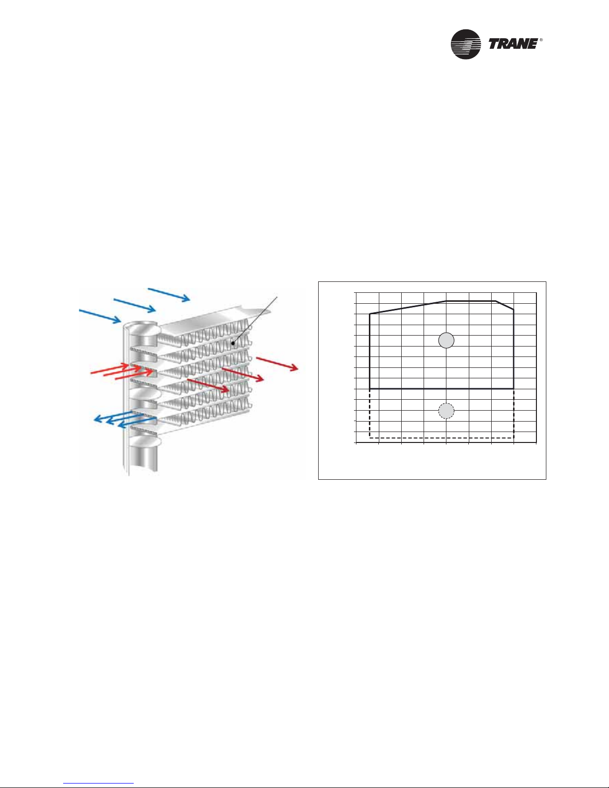
Figure 9 - Installation example
For maximum isolation effect, water lines and electrical
conduit should also be isolated. Wall sleeves and rubber
isolated piping hangers can be used to reduce the sound
transmitted through water piping. To reduce the sound
transmitted through electrical conduit, use flexible
electrical conduit.
Local codes on sound emissions should always be
considered. Since the environment in which a sound
source is located affects sound pressure, unit placement
must be carefully evaluated. Sound power levels for
chillers are available on request.
Servicing
Adequate clearance for evaporator and compressor
servicing should be provided. Recommended minimum
space envelopes for servicing are located in the
dimensional data section and can serve as a guideline
for providing adequate clearance.The minimum space
envelopes also allow for control panel door swing
and routine maintenance requirements. Local code
requirements may take precedence.
Unit Location
General
Unobstructed flow of condenser air is essential to
maintain chiller capacity and operating efficiency. When
determining unit placement, careful consideration
must be given to assure a sufficient flow of air across
the condenser heat transfer surface.Two detrimental
conditions are possible and must be avoided: warm air
recirculation and coil starvation. Air recirculation occurs
when discharge air from the condenser fans is recycled
back to the condenser coil inlet. Coil starvation occurs
when free airflow to the condenser is restricted.
Condenser coils and fan discharge must be kept free of
snow or other obstructions to permit adequate airflow
for satisfactory unit operation. Debris, trash, supplies,
etc., should not be allowed to accumulate in the vicinity
of the air-cooled chiller. Supply air movement may draw
debris into the condenser coil, blocking spaces between
coil fins and causing coil starvation.
Both warm air recirculation and coil starvation cause
reductions in unit efficiency and capacity because of
the higher head pressures associated with them.The
air-cooled Conquest chiller offers an advantage over
competitive equipment in these situations. Operation is
minimally affected in many restricted air flow situations
due to its advanced chiller controller.
Microprocessor which has the ability to understand the
operating environment of the chiller and adapt to it by
first optimizing its performance and then staying on
line through abnormal conditions. For example, high
ambient temperatures combined with a restricted air
flow situation will generally not cause the air-cooled
model CGAX chiller to shut down. Other chillers would
typically shut down on a high pressure nuisance cut-out
in these conditions.
Cross winds, those perpendicular to the condenser, tend
to aid efficient operation in warmer ambient conditions.
However, they tend to be detrimental to operation
in lower ambients due to the accompanying loss of
adequate head pressure. Special consideration should
be given to low ambient units. As a result, it is advisable
to protect air-cooled chillers from continuous direct
winds exceeding 4.5 m/s in low ambient conditions.
Chiled water piping
should be supported.
Isolators
Flexible electrical
conduit
Concrete base
Isolators
Piping isolation

CG-PRC026C-GB 11
Unit Placement
Provide Sufficient Unit-to-Unit Clearance
Units should be separated from each other by sufficient
distance to prevent warm air recirculation or coil
starvation. Doubling the recommended single unit
air-cooled chiller clearances will generally prove to be
adequate.
Walled Enclosure Installations
When the unit is placed in an enclosure or small
depression, the top of the surrounding walls should be
no higher than the top of the fans.The chiller should be
completely open above the fandeck.There should be no
roof or structure covering the top of the chiller. Ducting
individual fans is not recommended.

CG-PRC026C-GB
12
Model Number Description
Digit 1-4 — Chiller Model
CGAX: Cooling-only unit
CXAX: Heat pump unit
Digit 5-7 — Unit Nominal Size
015: 15 ton
017: 17 ton
020: 20 ton
023: 23 ton
026: 26 ton
030: 30 ton
036: 36 ton
039: 39 ton
045: 45 ton
035: 35 ton
040: 40 ton
046: 46 ton
052: 52 ton
060: 60 ton
Digit 8— Unit Voltage
E: 400V/3ph/50Hz
Digit 9 — Manufacturing Plant
1 = Europe
Digit 10-11 — Design Sequence
A: Factory asigned
0: Factory asigned
Digit 12 — Efficiency Level
1: Standard Efficiency Class (B)
2: High Efficiency
Digit 13 — Agency Listing
E: CE Certification
Digit 14 — Pressure Vessel Code
4: Pressure Equipment Directive (PED)
Digit 15— Condenser Temperature Range
A: Standard operating map (5°C/46°C)
C: Low Ambient Cooling (CGAX -18°C/46°C;
CXAX -10°C/46°C)
Digit 16, 17 — Open for future options
Digit 18— Freeze Protection (Factory-Installed Only)
X: Without freeze protection
2: With freeze protection by heaters
3: With freeze protection by pump activation
Digit 19, 20 — Open for future options
Digit 21 — Evaporator Application
A: Comfort application (5°C/20°C)
B: Process application (CGAX: -12°C/5°C;
CXAX: -10°C/5°C)
Digit 22 — Water Connection (Evaporator)
1: Grooved pipe
2: Grooved pipe, couplings and pipestub
Digit 23 — Condenser Fin Material
B: Standard aluminum fins on Heat Pumps
E: Epoxy aluminum fins on Heat Pumps
H: Microchannel (MCHE) on Cooling-only Units
J: E-coating on MCHE on Cooling-only units
Digit 24 — Condenser Heat Recovery
X: Without Heat Recovery
2: Partial Heat Recovery
Digit 25— Open for future options
Digit 26 — Starter Type
A: Across-the-line starter
B: Solid State Soft Starter
Digit 27, 28, 29 — Open for future options
Digit 30 — Human Interface
A: Standard display
B: Deluxe touch display
X: Without display
Digit 31 — Communication Options
X: Without remote communication
1: ModBus Interface
2: LonTalk Interface
3: Smart Web Interface
4: BACnet Interface
Digit 32 — Customer Input/Ouput Options
X: None
A: With

CG-PRC026C-GB 13
Model Number Description
Digit 33 — Smart Sequencer
X: None
Digit 34 — Open for future options
Digit 35— Hydraulic Module/Pump package type
X: Without contactors
2: Only contactors single pump
4: Only contactors twin pump
5: Single pump package low pressure
6: Single pump package high pressure
7: Dual pump package low pressure
8: Dual pump package high pressure
Digit 36 — Pump flow control
X: Constant flow
B: Manual flow control
C: Variable primary flow (constant DeltaT)
D: Variable primary flow (constant Delta P)
Digit 37 — Buffer Tank
X: NoTank
1: WithTank
Digit 38— Open digit for future options
Digit 39 — Installation Accessories
1: None
4: Neoprene pads
Digit 40 — Open digit for future options
Digit 41 — Acoustical options
2: High External Static Pressure
3: Standard
4: Low Noise
Digit 42 — Condenser Protection
A: Condenser guard grills
X: Without
Digit 43 — Open digit for future options
Digit 44 — Literature Language
B: Spanish
C: English
D: German
E: French
H: Dutch
J: Italian
M: Swedish
N:Turkish
P: Polish
T: Czech
U: Greek
V: Portuguese
Y: Romanian
3: Hungarian
Digit 45— Under/Over Voltage Protection
X: None
1: With
Digit 46 — Open for future options
Digit 47 — Customer witness performance test
X: None
Digit 48— Open for future options
Digit 49 — Supplementary Heat Control
1: With
X: Without
Digit 50 — Special design
X: Standard
S: Special design

CG-PRC026C-GB
14
General Data
Table 1 - CGAX Standard efficiency and Standard Noise
Eurovent Performances (1)
CGAX
015
SE-SN
CGAX
017
SE-SN
CGAX
020
SE-SN
CGAX
023
SE-SN
CGAX
026
SE-SN
CGAX
030
SE-SN
CGAX
036
SE-SN
Net Cooling Capacity (kW) 43 49 59 65 74 82 99
Total Power input in cooling (kW) 15 17 19 22 26 29 33
Total Power input in cooling - HESP Option (100Pa) (kW) 15 18 21 24 27 31 34
EER 2.98 2.88 3.08 2.95 2.87 2.84 2.96
EER - HESP (915 RPM - 100Pa) 2.82 2.74 2.89 2.81 2.78 2.76 2.81
ESEER 3.89 3.93 3.81 3.82 3.84 3.80 3.93
Eurovent Efficiency class Cooling BCBBCCB
Sound power level (dBA) 83 83 85 85 85 86 84
Sound power level - HESP Option (100Pa) (dBA) 85 85 89 89 89 89 89
Unit amps (4) (5)
Unit rated amps (A) 34 38 45 50 56 64 74
Unit rated amps - HESP Option (100Pa) (A) 35 39 47 52 57 66 75
Unit start up amps (A) 116 160 167 183 188 189 198
Unit start up amps - HESP Option (100Pa) (A) 117 161 169 185 190 191 199
Short Circuit Unit Capacity (9) (kA) 12 12 12 12 12 12 15
Compressor
Compressor Number per Circuit # 2222223
Type Scroll Scroll Scroll Scroll Scroll Scroll Scroll
Model Circuit1 / Circuit 2 7.5+7.5 7.5+10 10+10 10+13 13+13 15+15 12+12+12
Motor RPM (rpm) 2900
Evaporator
Quantity # 1111111
Type Stainless steel Copper Brazed plate Heat exchanger
Evaporator model P80x66 P80x92 P80x92 P80x92 P120Tx76 P120Tx76 P120Tx104
Evaporator Water Content volume (l) 3.8 5.3 5.3 5.3 9.2 9.2 12.5
Nominal water connection size (Grooved coupling) -
Without HYM (in) - (mm) 2” - 60.3 2” - 60.3 2” - 60.3 2” - 60.3 2” - 60.3 2” - 60.3 2” - 60.3
Nominal water connection size (Grooved coupling) -
With HYM (in) - (mm) 2” - 60.3 2” - 60.3 2” - 60.3 2” - 60.3 2” - 60.3 2” - 60.3 3” OD - 76.1
Hydraulic Module Components
Expansion Tank Volume (l) 25 25 25 25 25 25 35
Max User water loop Volume for factory mounted
expansion tank (1) (l) 1450 1450 1450 1450 1450 1450 2000
Optional water Buffer tank volume (l) 324 324 324 324 324 324 444
Max. Water-side Operating Pressure without pump
package (kPa) 1000
Max. Water-side Operating Pressure with pump
package (kPa) 400
Condenser
Type Full aluminum Micro channel heat exchanger
Quantity of coil # 1111112
Face area per circuit (m²) 2.23 2.23 2.96 2.96 2.96 2.96 4.46
Condenser Fan
Quantity # 1122222
Diameter (mm) 800
Fan / motor Type Propeller fan : Fixed speed AC motor / Variable speed - EC motor
Airflow per Fan (m3/h) 13788 13828 12362 12362 12370 12375 13827
Airflow per Fan - HESP Option (100Pa) (m3/h) 13753 13718 12248 12231 12211 12193 13727
Motor RPM (rpm) 686 686 686 686 686 686 686
Motor RPM - HESP Option (100Pa) (rpm) 915 915 915 915 915 915 915
Partial Heat recovery (PHR) option
Heat-Exchanger Type Stainless steel Copper Brazed plate Heat exchanger
Heat-Exchanger Model B3-014-14-4.5M B3-014-14-4.5M B3-014-14-4.5M B3-014-14-4.5M B3-027-14-4.5L B3-027-14-4.5L B3-027-14-4.5L
Water connection size (Thread connection) (in) - (mm) G 1”1/4
(31.75 mm)
G 1”1/4
(31.75 mm)
G 1”1/4
(31.75 mm)
G 1”1/4
(31.75 mm)
G 1”1/4
(31.75 mm)
G 1”1/4
(31.75 mm)
G 1”1/4
(31.75 mm)
Water content volume (l) 0.14 0.14 0.14 0.14 0.35 0.35 0.35
Dimensions
Unit Length (mm) 2346 2346 2346 2346 2346 2346 2327
Unit Width (mm) 1285 1285 1285 1285 1285 1285 2250
Unit Height (mm) 1524 1524 1524 1524 1524 1524 1524
Option Additional height
Water Buffer tank option (mm) +330 +330 +330 +330 +330 +330 +330
Weights
Shipping Weight (5) (kg) 519 531 574 579 608 621 853
Operating Weight (5) (kg) 497 509 552 557 587 599 819
Option Additional shipping weight
Single pump - Standard head pressure (kg) 46 46 46 49 49 49 45
Single pump - High head pressure (kg) 51 51 51 51 51 51 49
Twin pump - Standard head pressure (kg) 70 70 70 75 75 75 71
Twin pump - High head pressure (kg) 82 82 82 82 82 82 86
Partial heat recovery option (kg) 1.48 1.48 1.48 1.48 3.82 3.82 3.82
Water Buffer tank option (kg) 319 319 319 319 319 319 425
System data
Nb of refrigerant circuit # 1111111
Minimum cooling load % (6) % 50 43 50 43 50 50 33
Standard unit
R410A refrigerant charge Circuit1 / Circuit 2 (kg) 7.5 9.0 9.0 9.0 10.5 10.5 14.0
Oil charge Circuit1 / Circuit 2 (l) 6.0 6.3 6.6 6.6 6.6 7.2 10.5
Unit with partial heat recovery option
R410a refrigerant charge Circuit1 / Circuit 2 (kg) 7.5 9.0 9.0 9.0 10.5 10.5 14.0
Oil charge Circuit1 / Circuit 2 (l) 6.0 6.3 6.6 6.6 6.6 7.2 10.5
POE Oil type OIL058E / OIL057E
(1) At Evaporator water temperature : 12°C / 7°C - Condenser air temperature 35°C according to EN14511:2013
(2) At Evaporator water temperature : 6.6°C (44°F) / 12.2°C (54°F) - condenser air temperature 46°C (114.8°F)
(4) under 400V/3/50Hz
(5) Rated Condition without Pump Package
(6) Percent minimum load can be lowered on demand to local sales office.
(7) Minimum start-up/operation ambient based on a 2.22 m/s (5mph) wind across the condenser.
(8) Maximum ambient operation is for unit at 12°C / 7°C
(9) If the power line of the unit is protected by fuses gG of the same size as the disconnect switch.
Electrical & system data are subject to change without notice. Please refer to unit nameplate data.

CG-PRC026C-GB 15
General Data
Eurovent Performances (1)
CGAX
039
SE-SN
CGAX
045
SE-SN
CGAX
035
SE-SN
CGAX
040
SE-SN
CGAX
046
SE-SN
CGAX
052
SE-SN
CGAX
060
SE-SN
Net Cooling Capacity (kW) 111 127 97 116 129 147 164
Total Power input in cooling (kW) 38 41 35 39 47 51 58
Total Power input in cooling - HESP Option (100Pa) (kW) 39 45 36 43 50 57 61
EER 2.92 3.08 2.79 2.94 2.78 2.86 2.83
EER - HESP (915 RPM - 100Pa) 2.82 2.81 2.72 2.73 2.61 2.55 2.68
ESEER 4.13 3.98 3.83 3.64 3.59 3.75 3.81
Eurovent Efficiency class Cooling BCCBBCC
Sound power level (dBA) 85 87 86 88 88 88 89
Sound power level - HESP Option (100Pa) (dBA) 90 92 90 92 92 92 92
Unit amps (4) (5)
Unit rated amps (A) 81 96 77 90 101 111 128
Unit rated amps - HESP Option (100Pa) (A) 83 98 78 93 104 114 131
Unit start up amps (A) 214 221 198 212 233 243 253
Unit start up amps - HESP Option (100Pa) (A) 215 224 200 215 236 247 256
Short Circuit Unit Capacity (9) (kA) 15 15 15 15 15 15 15
Compressor
Compressor Number per Circuit # 3322222
Type Scroll Scroll Scroll Scroll Scroll Scroll Scroll
Model Circuit1 / Circuit 2 13+13+13 15+15+15 7.5+10 / 7.5+10 10+10 / 10+10 10+13 /10+13 13+13 / 13+13 15+15 / 15+15
Motor RPM (rpm) 2900
Evaporator
Quantity # 1111111
Type Stainless steel Copper Brazed plate Heat exchanger
Evaporator model P120Tx104 P120Tx104 DP300x82 DP300x82 DP300x82 DP300x114 DP300x114
Evaporator Water Content volume (l) 12.5 12.5 8.5 8.5 8.5 11.8 11.8
Nominal water connection size (Grooved coupling) -
Without HYM (in) - (mm) 2" - 60.3 2" - 60.3 3" OD - 76.1 3" OD - 76.1 3" OD - 76.1 3" OD - 76.1 3" OD - 76.1
Nominal water connection size (Grooved coupling) -
With HYM (in) - (mm) 3" OD - 76.1 3" OD - 76.1 3" OD - 76.1 3" OD - 76.1 3" OD - 76.1 3" OD - 76.1 3" OD - 76.1
Hydraulic Module Components
Expansion Tank Volume (l) 35 35 35 35 35 35 35
Max User water loop Volume for factory mounted
expansion tank (1) (l) 2000 2000 2000 2000 2000 2000 2000
Optional water Buffer tank volume (l) 444 444 444 444 444 444 444
Max. Water-side Operating Pressure without pump
package (kPa) 1000
Max. Water-side Operating Pressure with pump
package (kPa) 400
Condenser
Type Full aluminum Micro channel heat exchanger
Quantity of coil # 2222222
Face area per circuit (m²) 5.93 5.93 2.23 2.96 2.96 2.96 2.96
Condenser Fan
Quantity # 2324444
Diameter (mm) 800
Fan / motor Type Propeller fan : Fixed speed AC motor / Variable speed - EC motor
Airflow per Fan (m3/h) 14690 13676 14687 12358 12363 12592 12374
Airflow per Fan - HESP Option (100Pa) (m3/h) 14660 13595 14686 12249 12233 12447 12205
Motor RPM (rpm) 686 686 686 686 686 686 686
Motor RPM - HESP Option (100Pa) (rpm) 915 915 915 915 915 915 915
Partial Heat recovery (PHR) option
Heat-Exchanger Type Stainless steel Copper Brazed plate Heat exchanger
Heat-Exchanger Model B3-027-20-4.5L B3-027-20-4.5L 2xB3-014-14-4.5M 2xB3-014-14-4.5M 2xB3-014-14-4.5M 2xB3-027-14-4.5L 2xB3-027-14-4.5L
Water connection size (Thread connection) (in) - (mm) G 1”1/4
(31.75 mm)
G 1”1/4
(31.75 mm)
G 1”1/4
(31.75 mm)
G 1”1/4
(31.75 mm)
G 1”1/4
(31.75 mm)
G 1”1/4
(31.75 mm)
G 1”1/4
(31.75 mm)
Water content volume (l) 0.5 0.5 2x0.14 2x0.14 2x0.14 2x0.35 2x0.35
Dimensions
Unit Length (mm) 2327 2327 2327 2327 2327 2327 2327
Unit Width (mm) 2250 2250 2250 2250 2250 2250 2250
Unit Height (mm) 1524 1524 1524 1524 1524 1524 1524
Option Additional height
Water Buffer tank option (mm) +330 +330 +330 +330 +330 +330 +330
Weights
Shipping Weight (5) (kg) 858 912 917 1004 1014 1034 1060
Operating Weight (5) (kg) 824 879 887 973 983 1004 1029
Option Additional shipping weight
Single pump - Standard head pressure (kg) 47 47 45 47 47 47 47
Single pump - High head pressure (kg) 49 49 49 49 49 49 49
Twin pump - Standard head pressure (kg) 75 75 75 75 75 75 75
Twin pump - High head pressure (kg) 86 86 84 84 84 84 84
Partial heat recovery option (kg) 4.6 4.6 2x1.48 2x1.48 2x1.48 2x3.82 2x3.82
Water Buffer tank option (kg) 425 425 425 425 425 425 425
System data
Nb of refrigerant circuit # 1122222
Minimum cooling load % (6) % 33 33 22 25 22 25 25
Standard unit
R410A refrigerant charge Circuit1 / Circuit 2 (kg) 14.5 15.0 8.0 / 8.0 8.0 / 8.0 8.0 / 8.0 9.0 / 9.0 9.5 / 9.5
Oil charge Circuit1 / Circuit 2 (l) 10.5 11.5 6.3 / 6.3 6.6 / 6.6 6.6 / 6.6 6.6 / 6.6 7.2 / 7.2
Unit with partial heat recovery option
R410a refrigerant charge Circuit1 / Circuit 2 (kg) 14.5 15.0 8.0 / 8.0 8.0 / 8.0 8.0 / 8.0 9.0 / 9.0 9.5 / 9.5
Oil charge Circuit1 / Circuit 2 (l) 10.5 11.5 6.3 / 6.3 6.6 / 6.6 6.6 / 6.6 6.6 / 6.6 7.2 / 7.2
POE Oil type OIL058E / OIL057E
(1) At Evaporator water temperature : 12°C / 7°C - Condenser air temperature 35°C according to EN14511:2013
(2) At Evaporator water temperature : 6.6°C (44°F) / 12.2°C (54°F) - condenser air temperature 46°C(114.8°F)
(4) under 400V/3/50Hz
(5) Rated Condition without Pump Package
(6) Percent minimum load can be lowered on demand to local sales office.
(7) Minimum start-up/operation ambient based on a 2.22 m/s (5mph) wind across the condenser.
(8) Maximum ambient operation is for unit at 12°C / 7°C
(9) If the power line of the unit is protected by fuses gG of the same size as the disconnect switch.
Electrical & system data are subject to change without notice. Please refer to unit nameplate data.
Table 1 - CGAX Standard efficiency and Standard Noise (continued)

CG-PRC026C-GB
16
General Data
Table 2 - CGAX Standard efficiency and Low Noise
Eurovent Performances (1)
CGAX
015
SE-LN
CGAX
017
SE-LN
CGAX
020
SE-LN
CGAX
023
SE-LN
CGAX
026
SE-LN
CGAX
030
SE-LN
CGAX
036
SE-LN
Net Cooling Capacity (kW) 43 49 59 65 74 82 99
Total Power input in cooling (kW) 15 17 19 22 26 29 33
Total Power input in cooling - HESP Option (100Pa) (kW) 15 18 21 24 27 31 34
EER 2.98 2.88 3.08 2.95 2.87 2.84 2.96
EER - HESP Option (100Pa) 2.82 2.74 2.89 2.81 2.78 2.76 2.81
ESEER 3.89 3.93 3.81 3.82 3.84 3.80 3.93
Eurovent Efficiency class Cooling BCBBCCB
Sound power level (dBA) 77 77 79 79 79 80 79
Sound power level - HESP Option (100Pa) (dBA) 85 85 89 89 89 89 89
Unit amps (4) (5)
Unit rated amps (A) 34 38 45 50 56 64 74
Unit rated amps - HESP Option (100Pa) (A) 35 39 47 52 57 66 75
Unit start up amps (A) 116 160 167 183 188 189 198
Unit start up amps - HESP Option (100Pa) (A) 117 161 169 185 190 191 199
Short Circuit Unit Capacity (9) (kA) 12 12 12 12 12 12 15
Compressor
Compressor Number per Circuit # 2222223
Type Scroll Scroll Scroll Scroll Scroll Scroll Scroll
Model Circuit1 / Circuit 2 7.5+7.5 7.5+10 10+10 10+13 13+13 15+15 12+12+12
Motor RPM (rpm) 2900
Evaporator
Quantity # 1111111
Type Stainless steel Copper Brazed plate Heat exchanger
Evaporator model P80x66 P80x92 P80x92 P80x92 P120Tx76 P120Tx76 P120Tx104
Evaporator Water Content volume (l) 3.8 5.3 5.3 5.3 9.2 9.2 12.5
Nominal water connection size (Grooved coupling) -
Without HYM (in) - (mm) 2” - 60.3 2” - 60.3 2” - 60.3 2” - 60.3 2” - 60.3 2” - 60.3 2” - 60.3
Nominal water connection size (Grooved coupling) -
With HYM (in) - (mm) 2” - 60.3 2” - 60.3 2” - 60.3 2” - 60.3 2” - 60.3 2” - 60.3 3” OD - 76.1
Hydraulic Module Components
Expansion Tank Volume (l) 25 25 25 25 25 25 35
Max User water loop Volume for factory mounted
expansion tank (1) (l) 1450 1450 1450 1450 1450 1450 2000
Optional water Buffer tank volume (l) 324 324 324 324 324 324 444
Max. Water-side Operating Pressure without pump
package (kPa) 1000
Max. Water-side Operating Pressure with pump
package (kPa) 400
Condenser
Type Full aluminum Micro channel heat exchanger
Quantity of coil # 1111112
Face area per circuit (m²) 2.23 2.23 2.96 2.96 2.96 2.96 4.46
Condenser Fan
Quantity # 1122222
Diameter (mm) 800
Fan / motor Type Propeller fan : Fixed speed AC motor / Variable speed - EC motor
Airflow per Fan (m3/h) 13788 13828 12362 12362 12370 12375 13827
Airflow per Fan - HESP Option (100Pa) (m3/h) 13753 13718 12248 12231 12211 12193 13727
Motor RPM (rpm) 686 686 686 686 686 686 686
Motor RPM - HESP Option (100Pa) (rpm) 915 915 915 915 915 915 915
Partial Heat recovery (PHR) option
Heat-Exchanger Type Stainless steel Copper Brazed plate Heat exchanger
Heat-Exchanger Model B3-014-14-4.5M B3-014-14-4.5M B3-014-14-4.5M B3-014-14-4.5M B3-027-14-4.5L B3-027-14-4.5L B3-027-14-4.5L
Water connection size (Thread connection) (in) - (mm) G 1”1/4
(31.75 mm)
G 1”1/4
(31.75 mm)
G 1”1/4
(31.75 mm)
G 1”1/4
(31.75 mm)
G 1”1/4
(31.75 mm)
G 1”1/4
(31.75 mm)
G 1”1/4
(31.75 mm)
Water content volume (l) 0.14 0.14 0.14 0.14 0.35 0.35 0.35
Dimensions
Unit Length (mm) 2346 2346 2346 2346 2346 2346 2327
Unit Width (mm) 1285 1285 1285 1285 1285 1285 2250
Unit Height (mm) 1747 1747 1747 1747 1747 1747 1747
Option Additional height
Water Buffer tank option (mm) +330 +330 +330 +330 +330 +330 +330
Weights
Shipping Weight (5) (kg) 519 531 574 579 608 621 853
Operating Weight (5) (kg) 497 509 552 557 587 599 819
Option Additional shipping weight
Single pump - Standard head pressure (kg) 46 46 46 49 49 49 45
Single pump - High head pressure (kg) 51 51 51 51 51 51 49
Twin pump - Standard head pressure (kg) 70 70 70 75 75 75 71
Twin pump - High head pressure (kg) 82 82 82 82 82 82 86
Partial heat recovery option (kg) 1.48 1.48 1.48 1.48 3.82 3.82 3.82
Water Buffer tank option (kg) 319 319 319 319 319 319 425
System data
Nb of refrigerant circuit # 1111111
Minimum cooling load % (6) % 50 43 50 43 50 50 33
Standard unit
R410A refrigerant charge Circuit1 / Circuit 2 (kg) 7.5 9.0 9.0 9.0 10.5 10.5 14.0
Oil charge Circuit1 / Circuit 2 (l) 6.0 6.3 6.6 6.6 6.6 7.2 10.5
Unit with partial heat recovery option
R410a refrigerant charge Circuit1 / Circuit 2 (kg) 7.5 9.0 9.0 9.0 10.5 10.5 14.0
Oil charge Circuit1 / Circuit 2 (l) 6.0 6.3 6.6 6.6 6.6 7.2 10.5
POE Oil type OIL058E / OIL057E
(1) At Evaporator water temperature : 12°C / 7°C - Condenser air temperature 35°C according to EN14511:2013
(4) under 400V/3/50Hz
(5) Rated Condition without Pump Package
(6) Percent minimum load can be lowered on demand to local sales office.
(7) Minimum start-up/operation ambient based on a 2.22 m/s (5mph) wind across the condenser.
(8) Maximum ambient operation is for unit at 12°C / 7°C
(9) If the power line of the unit is protected by fuses gG of the same size as the disconnect switch.
Electrical & system data are subject to change without notice. Please refer to unit nameplate data.

CG-PRC026C-GB 17
General Data
Table 2 - CGAX Standard efficiency and Low Noise (continued)
Eurovent Performances (1)
CGAX
039
SE-LN
CGAX
045
SE-LN
CGAX
035
SE-LN
CGAX
040
SE-LN
CGAX
046
SE-LN
CGAX
052
SE-LN
CGAX
060
SE-LN
Net Cooling Capacity (kW) 111 127 97 116 129 147 164
Total Power input in cooling (kW) 38 41 35 39 47 51 58
Total Power input in cooling - HESP Option (100Pa) (kW) 39 45 36 43 50 57 61
EER 2.92 3.08 2.79 2.94 2.78 2.86 2.83
EER - HESP Option (100Pa) 2.82 2.81 2.72 2.73 2.61 2.55 2.68
ESEER 4.13 3.98 3.83 3.64 3.59 3.75 3.81
Eurovent Efficiency class Cooling BCCBBCC
Sound power level (dBA) 80 82 81 82 82 82 83
Sound power level - HESP Option (100Pa) (dBA) 90 92 90 92 92 92 92
Unit amps (4) (5)
Unit rated amps (A) 81 96 77 90 101 111 128
Unit rated amps - HESP Option (100Pa) (A) 83 98 78 93 104 114 131
Unit start up amps (A) 214 221 198 212 233 243 253
Unit start up amps - HESP Option (100Pa) (A) 215 224 200 215 236 247 256
Short Circuit Unit Capacity (9) (kA) 15 15 15 15 15 15 15
Compressor
Compressor Number per Circuit # 3322222
Type Scroll Scroll Scroll Scroll Scroll Scroll Scroll
Model Circuit1 / Circuit 2 13+13+13 15+15+15 7.5+10 / 7.5+10 10+10 / 10+10 10+13 /10+13 13+13 / 13+13 15+15 / 15+15
Motor RPM (rpm) 2900
Evaporator
Quantity # 1111111
Type Stainless steel Copper Brazed plate Heat exchanger
Evaporator model P120Tx104 P120Tx104 DP300x82 DP300x82 DP300x82 DP300x114 DP300x114
Evaporator Water Content volume (l) 12.5 12.5 8.5 8.5 8.5 11.8 11.8
Nominal water connection size (Grooved coupling) -
Without HYM (in) - (mm) 2” - 60.3 2” - 60.3 3” OD - 76.1 3” OD - 76.1 3” OD - 76.1 3” OD - 76.1 3” OD - 76.1
Nominal water connection size (Grooved coupling) -
With HYM (in) - (mm) 3” OD - 76.1 3” OD - 76.1 3” OD - 76.1 3” OD - 76.1 3” OD - 76.1 3” OD - 76.1 3” OD - 76.1
Hydraulic Module Components
Expansion Tank Volume (l) 35 35 35 35 35 35 35
Max User water loop Volume for factory mounted
expansion tank (1) (l) 2000 2000 2000 2000 2000 2000 2000
Optional water Buffer tank volume (l) 444 444 444 444 444 444 444
Max. Water-side Operating Pressure without pump
package (kPa) 1000
Max. Water-side Operating Pressure with pump
package (kPa) 400
Condenser
Type Full aluminum Micro channel heat exchanger
Quantity of coil # 2222222
Face area per circuit (m²) 5.93 5.93 2.23 2.96 2.96 2.96 2.96
Condenser Fan
Quantity # 2324444
Diameter (mm) 800
Fan / motor Type Propeller fan : Fixed speed AC motor / Variable speed - EC motor
Airflow per Fan (m3/h) 14690 13676 14687 12358 12363 12592 12374
Airflow per Fan - HESP Option (100Pa) (m3/h) 14660 13595 14686 12249 12233 12447 12205
Motor RPM (rpm) 686 686 686 686 686 686 686
Motor RPM - HESP Option (100Pa) (rpm) 915 915 915 915 915 915 915
Partial Heat recovery (PHR) option
Heat-Exchanger Type Stainless steel Copper Brazed plate Heat exchanger
Heat-Exchanger Model B3-027-20-4.5L B3-027-20-4.5L 2xB3-014-14-4.5M 2xB3-014-14-4.5M 2xB3-014-14-4.5M 2xB3-027-14-4.5L 2xB3-027-14-4.5L
Water connection size (Thread connection) (in) - (mm) G 1”1/4
(31.75 mm)
G 1”1/4
(31.75 mm)
G 1”1/4
(31.75 mm)
G 1”1/4
(31.75 mm)
G 1”1/4
(31.75 mm)
G 1”1/4
(31.75 mm)
G 1”1/4
(31.75 mm)
Water content volume (l) 0.5 0.5 2x0.14 2x0.14 2x0.14 2x0.35 2x0.35
Dimensions
Unit Length (mm) 2327 2327 2327 2327 2327 2327 2327
Unit Width (mm) 2250 2250 2250 2250 2250 2250 2250
Unit Height (mm) 1747 1747 1747 1747 1747 1747 1747
Option Additional height
Water Buffer tank option (mm) +330 +330 +330 +330 +330 +330 +330
Weights
Shipping Weight (5) (kg) 858 912 917 1004 1014 1034 1060
Operating Weight (5) (kg) 824 879 887 973 983 1004 1029
Option Additional shipping weight
Single pump - Standard head pressure (kg) 47 47 45 47 47 47 47
Single pump - High head pressure (kg) 49 49 49 49 49 49 49
Twin pump - Standard head pressure (kg) 75 75 75 75 75 75 75
Twin pump - High head pressure (kg) 86 86 84 84 84 84 84
Partial heat recovery option (kg) 4.6 4.6 2x1.48 2x1.48 2x1.48 2x3.82 2x3.82
Water Buffer tank option (kg) 425 425 425 425 425 425 425
System data
Nb of refrigerant circuit # 1122222
Minimum cooling load % (6) % 33 33 22 25 22 25 25
Standard unit
R410A refrigerant charge Circuit1 / Circuit 2 (kg) 14.5 15.0 8.0 / 8.0 8.0 / 8.0 8.0 / 8.0 9.0 / 9.0 9.5 / 9.5
Oil charge Circuit1 / Circuit 2 (l) 10.5 11.5 6.3 / 6.3 6.6 / 6.6 6.6 / 6.6 6.6 / 6.6 7.2 / 7.2
Unit with partial heat recovery option
R410a refrigerant charge Circuit1 / Circuit 2 (kg) 14.5 15.0 8.0 / 8.0 8.0 / 8.0 8.0 / 8.0 9.0 / 9.0 9.5 / 9.5
Oil charge Circuit1 / Circuit 2 (l) 10.5 11.5 6.3 / 6.3 6.6 / 6.6 6.6 / 6.6 6.6 / 6.6 7.2 / 7.2
POE Oil type OIL058E / OIL057E
(1) At Evaporator water temperature : 12°C / 7°C - Condenser air temperature 35°C according to EN14511:2013
(4) under 400V/3/50Hz
(5) Rated Condition without Pump Package
(6) Percent minimum load can be lowered on demand to local sales office.
(7) Minimum start-up/operation ambient based on a 2.22 m/s (5mph) wind across the condenser.
(8) Maximum ambient operation is for unit at 12°C / 7°C
(9) If the power line of the unit is protected by fuses gG of the same size as the disconnect switch.
Electrical & system data are subject to change without notice. Please refer to unit nameplate data.

CG-PRC026C-GB
18
General Data
Table 3 - CGAX High Efficiency and Standard Noise
Eurovent Performances (1)
CGAX
015
HE-SN
CGAX
017
HE-SN
CGAX
020
HE-SN
CGAX
023
HE-SN
CGAX
026
HE-SN
CGAX
030
HE-SN
CGAX
036
HE-SN
Net Cooling Capacity (kW) 43 49 59 65 74 82 99
Total Power input in cooling (kW) 15 17 19 22 26 29 33
EER 2.98 2.88 3.08 2.95 2.87 2.84 2.96
ESEER 3.97 3.98 3.96 4.03 3.93 3.86 4.04
Eurovent Efficiency class Cooling BCBBCCB
Sound power level (dBA) 83 83 85 85 85 86 84
Unit amps (4) (5)
Unit rated amps (A) 35 39 47 52 57 66 75
Unit rated amps - HESP Option (100Pa) (A) 35 39 47 52 57 66 75
Unit start up amps (A) 117 161 169 185 190 191 199
Unit start up amps - HESP Option (100Pa) (A) 117 161 169 185 190 191 199
Short Circuit Unit Capacity (9) (kA) 12 12 12 12 12 12 15
Compressor
Compressor Number per Circuit # 2222223
Type Scroll Scroll Scroll Scroll Scroll Scroll Scroll
Model Circuit1 / Circuit 2 7.5+7.5 7.5+10 10+10 10+13 13+13 15+15 12+12+12
Motor RPM (rpm) 2900
Evaporator
Quantity # 1111111
Type Stainless steel Copper Brazed plate Heat exchanger
Evaporator model P80x66 P80x92 P80x92 P80x92 P120Tx76 P120Tx76 P120Tx104
Evaporator Water Content volume (l) 3.8 5.3 5.3 5.3 9.2 9.2 12.5
Nominal water connection size (Grooved coupling) -
Without HYM (in) - (mm) 2” - 60.3 2” - 60.3 2” - 60.3 2” - 60.3 2” - 60.3 2” - 60.3 2” - 60.3
Nominal water connection size (Grooved coupling) -
With HYM (in) - (mm) 2” - 60.3 2” - 60.3 2” - 60.3 2” - 60.3 2” - 60.3 2” - 60.3 3” OD - 76.1
Hydraulic Module Components
Expansion Tank Volume (l) 25 25 25 25 25 25 35
Max User water loop Volume for factory mounted
expansion tank (1) (l) 1450 1450 1450 1450 1450 1450 2000
Optional water Buffer tank volume (l) 324 324 324 324 324 324 444
Max. Water-side Operating Pressure without pump
package (kPa) 1000
Max. Water-side Operating Pressure with pump
package (kPa) 400
Condenser
Type Full aluminum Micro channel heat exchanger
Quantity of coil # 1111112
Face area per circuit (m²) 2.23 2.23 2.96 2.96 2.96 2.96 4.46
Condenser Fan
Quantity # 1122222
Diameter (mm) 800
Fan / motor Type Propeller fan : Variable speed - EC motor / HESP MAX SPEED
Airflow per Fan (m3/h) 13788 13828 12362 12362 12370 12375 13827
Motor RPM (rpm) 150 - 686 RPM
Partial Heat recovery (PHR) option
Heat-Exchanger Type Stainless steel Copper Brazed plate Heat exchanger
Heat-Exchanger Model B3-014-14-4.5M B3-014-14-4.5M B3-014-14-4.5M B3-014-14-4.5M B3-027-14-4.5L B3-027-14-4.5L B3-027-14-4.5L
Water connection size (Thread connection) (in) - (mm) G 1”1/4
(31.75 mm)
G 1”1/4
(31.75 mm)
G 1”1/4
(31.75 mm)
G 1”1/4
(31.75 mm)
G 1”1/4
(31.75 mm)
G 1”1/4
(31.75 mm)
G 1”1/4
(31.75 mm)
Water content volume (l) 0.14 0.14 0.14 0.14 0.35 0.35 0.35
Dimensions
Unit Length (mm) 2346 2346 2346 2346 2346 2346 2327
Unit Width (mm) 1285 1285 1285 1285 1285 1285 2250
Unit Height (mm) 1524 1524 1524 1524 1524 1524 1524
Option Additional height
Water Buffer tank option (mm) +330 +330 +330 +330 +330 +330 +330
Weights
Shipping Weight (5) (kg) 519 531 574 579 608 621 853
Operating Weight (5) (kg) 497 509 552 557 587 599 819
Option Additional shipping weight
Single pump - Standard head pressure (kg) 46 46 46 49 49 49 45
Single pump - High head pressure (kg) 51 51 51 51 51 51 49
Twin pump - Standard head pressure (kg) 70 70 70 75 75 75 71
Twin pump - High head pressure (kg) 82 82 82 82 82 82 86
Partial heat recovery option (kg) 1.48 1.48 1.48 1.48 3.82 3.82 3.82
Water Buffer tank option (kg) 319 319 319 319 319 319 425
System data
Nb of refrigerant circuit # 1111111
Minimum cooling load % (6) % 50 43 50 43 50 50 33
Standard unit
R410A refrigerant charge Circuit1 / Circuit 2 (kg) 7.5 9.0 9.0 9.0 10.5 10.5 14.0
Oil charge Circuit1 / Circuit 2 (l) 6.0 6.3 6.6 6.6 6.6 7.2 10.5
Unit with partial heat recovery option
R410a refrigerant charge Circuit1 / Circuit 2 (kg) 7.5 9.0 9.0 9.0 10.5 10.5 14.0
Oil charge Circuit1 / Circuit 2 (l) 6.0 6.3 6.6 6.6 6.6 7.2 10.5
POE Oil type OIL058E / OIL057E
(1) At Evaporator water temperature : 12°C / 7°C - Condenser air temperature 35°C according to EN14511:2013
(2) At Evaporator water temperature : 6.6°C (44°F) / 12.2°C (54°F) - condenser air temperature 46°C (114.8°F)
(4) under 400V/3/50Hz
(5) Rated Condition without Pump Package
(6) Percent minimum load can be lowered on demand to local sales office.
(7) Minimum start-up/operation ambient based on a 2.22 m/s (5mph) wind across the condenser.
(8) Maximum ambient operation is for unit at 12°C / 7°C
(9) If the power line of the unit is protected by fuses gG of the same size as the disconnect switch.
Electrical & system data are subject to change without notice. Please refer to unit nameplate data.

CG-PRC026C-GB 19
General Data
Table 3 - CGAX High Efficiency and Standard Noise (continued)
Eurovent Performances (1)
CGAX
039
HE-SN
CGAX
045
HE-SN
CGAX
035
HE-SN
CGAX
040
HE-SN
CGAX
046
HE-SN
CGAX
052
HE-SN
CGAX
060
HE-SN
Net Cooling Capacity (kW) 111 127 97 116 129 147 164
Total Power input in cooling (kW) 38 41 35 39 47 51 58
EER 2.92 3.08 2.79 2.94 2.78 2.86 2.83
ESEER 4.22 4.14 3.87 3.82 3.76 3.84 3.88
Eurovent Efficiency class Cooling BCCBBCC
Sound power level (dBA) 85 87 86 88 88 88 89
Unit amps (4) (5)
Unit rated amps (A) 83 98 78 93 104 114 131
Unit rated amps - HESP Option (100Pa) (A) 83 98 78 93 104 114 131
Unit start up amps (A) 215 224 200 215 236 247 256
Unit start up amps - HESP Option (100Pa) (A) 215 224 200 215 236 247 256
Short Circuit Unit Capacity (9) (kA) 15 15 15 15 15 15 15
Compressor
Compressor Number per Circuit # 3322222
Type Scroll Scroll Scroll Scroll Scroll Scroll Scroll
Model Circuit1 / Circuit 2 13+13+13 15+15+15 7.5+10 / 7.5+10 10+10 / 10+10 10+13 /10+13 13+13 / 13+13 15+15 / 15+15
Motor RPM (rpm) 2900
Evaporator
Quantity # 1111111
Type Stainless steel Copper Brazed plate Heat exchanger
Evaporator model P120Tx104 P120Tx104 DP300x82 DP300x82 DP300x82 DP300x114 DP300x114
Evaporator Water Content volume (l) 12.5 12.5 8.5 8.5 8.5 11.8 11.8
Nominal water connection size (Grooved coupling) -
Without HYM (in) - (mm) 2” - 60.3 2” - 60.3 3” OD - 76.1 3” OD - 76.1 3” OD - 76.1 3” OD - 76.1 3” OD - 76.1
Nominal water connection size (Grooved coupling) -
With HYM (in) - (mm) 3” OD - 76.1 3” OD - 76.1 3” OD - 76.1 3” OD - 76.1 3” OD - 76.1 3” OD - 76.1 3” OD - 76.1
Hydraulic Module Components
Expansion Tank Volume (l) 35 35 35 35 35 35 35
Max User water loop Volume for factory mounted
expansion tank (1) (l) 2000 2000 2000 2000 2000 2000 2000
Optional water Buffer tank volume (l) 444 444 444 444 444 444 444
Max. Water-side Operating Pressure without pump
package (kPa) 1000
Max. Water-side Operating Pressure with pump
package (kPa) 400
Condenser
Type Full aluminum Micro channel heat exchanger
Quantity of coil # 2222222
Face area per circuit (m²) 5.93 5.93 2.23 2.96 2.96 2.96 2.96
Condenser Fan
Quantity # 2324444
Diameter (mm) 800
Fan / motor Type Propeller fan : Variable speed - EC motor / HESP MAX SPEED
Airflow per Fan (m3/h) 14690 13676 14687 12358 12363 12592 12374
Motor RPM (rpm) 150 - 686 RPM
Partial Heat recovery (PHR) option
Heat-Exchanger Type Stainless steel Copper Brazed plate Heat exchanger
Heat-Exchanger Model B3-027-20-4.5L B3-027-20-4.5L 2xB3-014-14-4.5M 2x B3-014-14-4.5M 2x B3-014-14-4.5M 2x B3-027-14-4.5L 2x B3-027-14-4.5L
Water connection size (Thread connection) (in) - (mm) G 1”1/4
(31.75 mm)
G 1”1/4
(31.75 mm)
G 1”1/4
(31.75 mm)
G 1”1/4
(31.75 mm)
G 1”1/4
(31.75 mm)
G 1”1/4
(31.75 mm)
G 1”1/4
(31.75 mm)
Water content volume (l) 0.5 0.5 2x 0.14 2x 0.14 2x 0.14 2x 0.35 2x 0.35
Dimensions
Unit Length (mm) 2327 2327 2327 2327 2327 2327 2327
Unit Width (mm) 2250 2250 2250 2250 2250 2250 2250
Unit Height (mm) 1524 1524 1524 1524 1524 1524 1524
Option Additional height
Water Buffer tank option (mm) +330 +330 +330 +330 +330 +330 +330
Weights
Shipping Weight (5) (kg) 858 912 917 1004 1014 1034 1060
Operating Weight (5) (kg) 824 879 887 973 983 1004 1029
Option Additional shipping weight
Single pump - Standard head pressure (kg) 47 47 45 47 47 47 47
Single pump - High head pressure (kg) 49 49 49 49 49 49 49
Twin pump - Standard head pressure (kg) 75 75 75 75 75 75 75
Twin pump - High head pressure (kg) 86 86 84 84 84 84 84
Partial heat recovery option (kg) 4.6 4.6 2x1.48 2x1.48 2x1.48 2x3.82 2x3.82
Water Buffer tank option (kg) 425 425 425 425 425 425 425
System data
Nb of refrigerant circuit # 1122222
Minimum cooling load % (6) % 33 33 22 25 22 25 25
Standard unit
R410A refrigerant charge Circuit1 / Circuit 2 (kg) 14.5 15.0 8.0 / 8.0 8.0 / 8.0 8.0 / 8.0 9.0 / 9.0 9.5 / 9.5
Oil charge Circuit1 / Circuit 2 (l) 10.5 11.5 6.3 / 6.3 6.6 / 6.6 6.6 / 6.6 6.6 / 6.6 7.2 / 7.2
Unit with partial heat recovery option
R410a refrigerant charge Circuit1 / Circuit 2 (kg) 14.5 15.0 8.0 / 8.0 8.0 / 8.0 8.0 / 8.0 9.0 / 9.0 9.5 / 9.5
Oil charge Circuit1 / Circuit 2 (l) 10.5 11.5 6.3 / 6.3 6.6 / 6.6 6.6 / 6.6 6.6 / 6.6 7.2 / 7.2
POE Oil type OIL058E / OIL057E
(1) At Evaporator water temperature : 12°C / 7°C - Condenser air temperature 35°C according to EN14511:2013
(2) At Evaporator water temperature : 6.6°C (44°F) / 12.2°C (54°F) - condenser air temperature 46°C (114.8°F)
(4) under 400V/3/50Hz
(5) Rated Condition without Pump Package
(6) Percent minimum load can be lowered on demand to local sales office.
(7) Minimum start-up/operation ambient based on a 2.22 m/s (5mph) wind across the condenser.
(8) Maximum ambient operation is for unit at 12°C / 7°C
(9) If the power line of the unit is protected by fuses gG of the same size as the disconnect switch.
Electrical & system data are subject to change without notice. Please refer to unit nameplate data.

CG-PRC026C-GB
20
General Data
Table 4 - CGAX High Efficiency and Low Noise
Eurovent Performances (1)
CGAX
015
HE-LN
CGAX
017
HE-LN
CGAX
020
HE-LN
CGAX
023
HE-LN
CGAX
026
HE-LN
CGAX
030
HE-LN
CGAX
036
HE-LN
Net Cooling Capacity (kW) 43 49 59 65 74 82 99
Total Power input in cooling (kW) 15 17 19 22 26 29 33
EER 2.98 2.88 3.08 2.95 2.87 2.84 2.96
ESEER 3.97 3.98 3.96 4.03 3.93 3.86 4.04
Eurovent Efficiency class Cooling BCBBCCB
Sound power level (dBA) 77 77 79 79 79 80 79
Unit amps (4) (5)
Unit rated amps (A) 35 39 47 52 57 66 75
Unit rated amps - HESP Option (100Pa) (A) 35 39 47 52 57 66 75
Unit start up amps (A) 117 161 169 185 190 191 199
Unit start up amps - HESP Option (100Pa) (A) 117 161 169 185 190 191 199
Short Circuit Unit Capacity (9) (kA) 12 12 12 12 12 12 15
Compressor
Compressor Number per Circuit # 2222223
Type Scroll Scroll Scroll Scroll Scroll Scroll Scroll
Model Circuit1 / Circuit 2 7.5+7.5 7.5+10 10+10 10+13 13+13 15+15 12+12+12
Motor RPM (rpm) 2900
Evaporator
Quantity # 1111111
Type Stainless steel Copper Brazed plate Heat exchanger
Evaporator model P80x66 P80x92 P80x92 P80x92 P120Tx76 P120Tx76 P120Tx104
Evaporator Water Content volume (l) 3.8 5.3 5.3 5.3 9.2 9.2 12.5
Nominal water connection size (Grooved coupling) -
Without HYM (in) - (mm) 2” - 60.3 2” - 60.3 2” - 60.3 2” - 60.3 2” - 60.3 2” - 60.3 2” - 60.3
Nominal water connection size (Grooved coupling) -
With HYM (in) - (mm) 2” - 60.3 2” - 60.3 2” - 60.3 2” - 60.3 2” - 60.3 2” - 60.3 3” OD - 76.1
Hydraulic Module Components
Expansion Tank Volume (l) 25 25 25 25 25 25 35
Max User water loop Volume for factory mounted
expansion tank (1) (l) 1450 1450 1450 1450 1450 1450 2000
Optional water Buffer tank volume (l) 324 324 324 324 324 324 444
Max. Water-side Operating Pressure without pump
package (kPa) 1000
Max. Water-side Operating Pressure with pump
package (kPa) 400
Condenser
Type Full aluminum Micro channel heat exchanger
Quantity of coil # 1111112
Face area per circuit (m²) 2.23 2.23 2.96 2.96 2.96 2.96 4.46
Condenser Fan
Quantity # 1122222
Diameter (mm) 800
Fan / motor Type Propeller fan : Variable speed - EC motor
Airflow per Fan (m3/h) 13788 13828 12362 12362 12370 12375 13827
Motor RPM (rpm) 150 - 686 RPM
Partial Heat recovery (PHR) option
Heat-Exchanger Type Stainless steel Copper Brazed plate Heat exchanger
Heat-Exchanger Model B3-014-14-4.5M B3-014-14-4.5M B3-014-14-4.5M B3-014-14-4.5M B3-027-14-4.5L B3-027-14-4.5L B3-027-14-4.5L
Water connection size (Thread connection) (in) - (mm) G 1”1/4
(31.75 mm)
G 1”1/4
(31.75 mm)
G 1”1/4
(31.75 mm)
G 1”1/4
(31.75 mm)
G 1”1/4
(31.75 mm)
G 1”1/4
(31.75 mm)
G 1”1/4
(31.75 mm)
Water content volume (l) 0.14 0.14 0.14 0.14 0.35 0.35 0.35
Dimensions
Unit Length (mm) 2346 2346 2346 2346 2346 2346 2327
Unit Width (mm) 1285 1285 1285 1285 1285 1285 2250
Unit Height (mm) 1747 1747 1747 1747 1747 1747 1747
Option Additional height
Water Buffer tank option (mm) +330 +330 +330 +330 +330 +330 +330
Weights
Shipping Weight (5) (kg) 519 531 574 579 608 621 853
Operating Weight (5) (kg) 497 509 552 557 587 599 819
Option Additional shipping weight
Single pump - Standard head pressure (kg) 46 46 46 49 49 49 45
Single pump - High head pressure (kg) 51 51 51 51 51 51 49
Twin pump - Standard head pressure (kg) 70 70 70 75 75 75 71
Twin pump - High head pressure (kg) 82 82 82 82 82 82 86
Partial heat recovery option (kg) 1.48 1.48 1.48 1.48 3.82 3.82 3.82
Water Buffer tank option (kg) 319 319 319 319 319 319 425
System data
Nb of refrigerant circuit # 1111111
Minimum cooling load % (6) % 50 43 50 43 50 50 33
Standard unit
R410A refrigerant charge Circuit1 / Circuit 2 (kg) 7.5 9.0 9.0 9.0 10.5 10.5 14.0
Oil charge Circuit1 / Circuit 2 (l) 6.0 6.3 6.6 6.6 6.6 7.2 10.5
Unit with partial heat recovery option
R410a refrigerant charge Circuit1 / Circuit 2 (kg) 7.5 9.0 9.0 9.0 10.5 10.5 14.0
Oil charge Circuit1 / Circuit 2 (l) 6.0 6.3 6.6 6.6 6.6 7.2 10.5
POE Oil type OIL058E / OIL057E
(1) At Evaporator water temperature : 12°C / 7°C - Condenser air temperature 35°C according to EN14511:2013
(4) under 400V/3/50Hz
(5) Rated Condition without Pump Package
(6) Percent minimum load can be lowered on demand to local sales office.
(7) Minimum start-up/operation ambient based on a 2.22 m/s (5mph) wind across the condenser.
(8) Maximum ambient operation is for unit at 12°C / 7°C
(9) If the power line of the unit is protected by fuses gG of the same size as the disconnect switch.
Electrical & system data are subject to change without notice. Please refer to unit nameplate data.
Table of contents
Other Trane Air Compressor manuals
Popular Air Compressor manuals by other brands

Craftsman
Craftsman 921.166420 owner's manual

Husky
Husky Trim-Plus H1503TP-R Operator's manual

California Air Tools
California Air Tools 8010ALFCAD owner's manual

DeWalt
DeWalt DXCMH9919910 instruction manual

Vixen Air
Vixen Air VXO4840B installation guide

Harbor Freight Tools
Harbor Freight Tools 67696 Startup guide