Trane COL32491 Assembly instructions

ALL phases of this installation must comply with NATIONAL, STATE AND LOCAL CODES
IMPORTANT — This Document is customer property and is to remain with this unit. Please return to service informa-
tion pack upon completion of work.
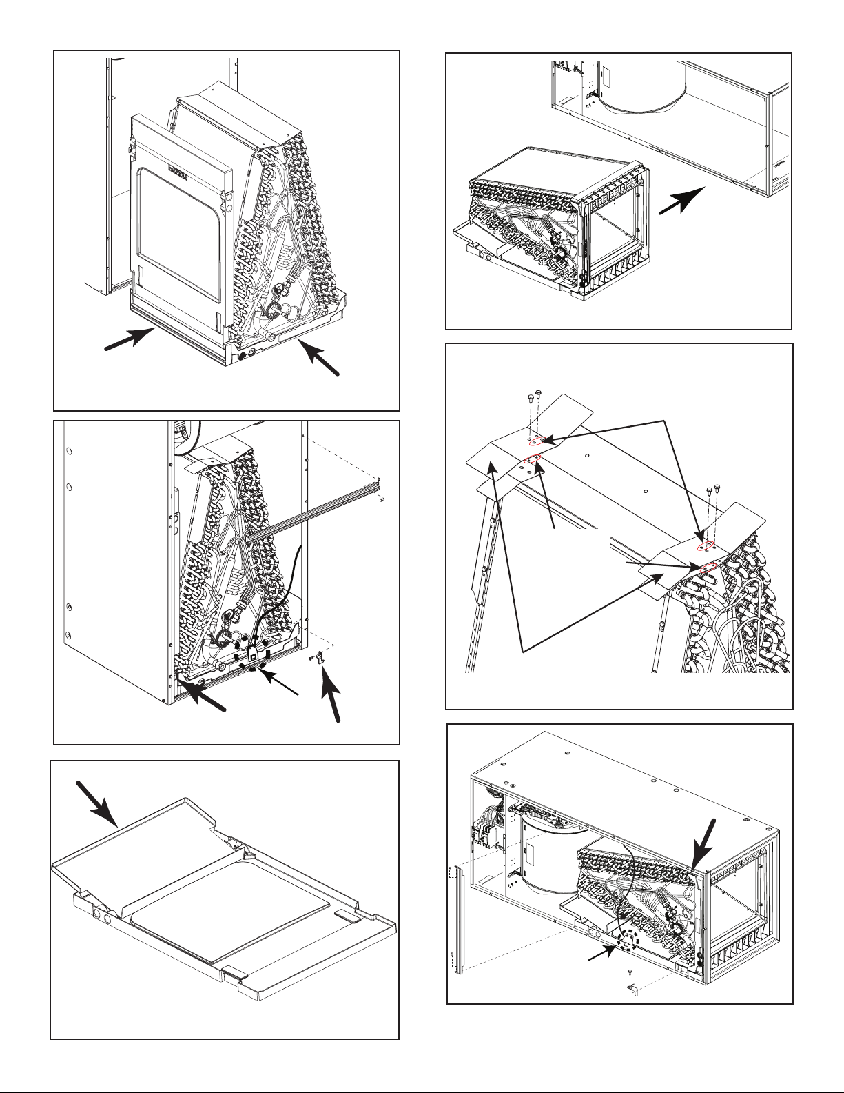
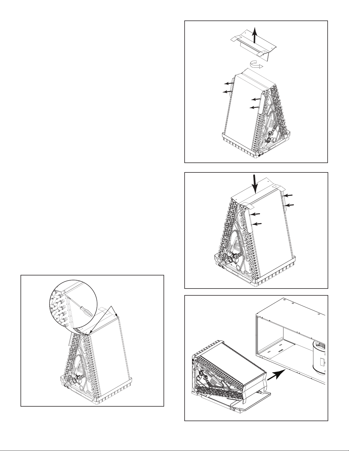
Replacement Coils
These instructions do not cover all variations in systems nor provide for every possible contingency to be met in connection with
the installation. Should further information be desired or should particular problems arise which are not covered sufficiently for the
purchaser’s purposes, the matter should be referred to your installing dealer or local distributor.
Installer’s Guide
Includes coil models
COL32491, 32492, 32493, 32494, 32495, 32496,
COL32499, 32500, 32501, 32502, 32503, 32504
18-AH77D1-1A-EN
1. Safety
This information is intended for use by individuals
possessing adequate backgrounds of electrical and
mechanical experience. Any attempt to repair a central
air conditioning product may result in personal injury
and/or property damage. The manufacture or seller
cannot be responsible for the interpretation of this
information, nor can it assume any liability in connec-
tion with its use.
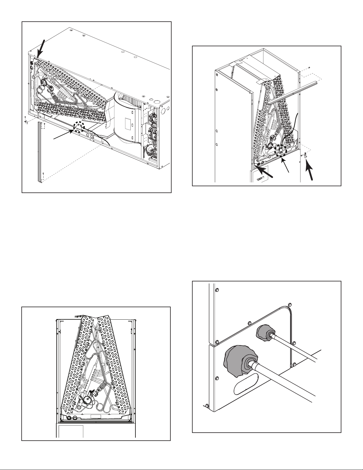
Extreme caution should be exercised when opening
the Liquid Line Service Valve. Turn counterclockwise
until the valve stem just touches the rolled edge. No
torque is required.
LIVE ELECTRICAL COMPONENTS!
Failure to follow this warning could result in property
damage, severe personal injury, or death.
Follow all electrical safety precautions when exposed
to live electrical components. It may be necessary to
work with live electrical components during installa-
tions, testing, servicing, and troubleshooting of this
product.
CAUTION
PRESSURIZED REFRIGERANT!
Failure to follow this warning could result in personal
injury.
System contains oil and refrigerant under high pres-
sure. Recover refrigerant to relieve pressure before
opening the system. Do not use non-approved refrig-
erants, refrigerant substitutes, or refrigerant additives.
SHARP EDGE HAZARD!
Failure to follow this caution could result in property
damage or severe personal injury.
Be careful of sharp edges on equipment or any cuts
made on sheet metal while installing or servicing.
CAUTION
RISK OF FIRE!
In systems using flammable refrigerants, observe all
safety instructions and markings with the air handler.
Ensure all safety devices are in place and functional.
To be repaired only by trained professional. Do not
puncture refrigerant tubing. Dispose of properly in ac-
cordance with federal or local regulations..
WARNING!
This product can expose you to chemicals including
lead, which are known to the State of California to
cause cancer and birth defects or other reproductive
harm.
For more information go to www.P65Warning.ca.gov.
COIL IS PRESSURIZED!
• Coil is pressurized with approximately 8-12 psi dry
air and factory checked for leaks.
• Carefully release the pressure by removing the
rubber plug on the liquid line.
• If no pressure is released, check for leaks.

218-AH77D1-1A-EN
3. General Information
These instructions are designed for installing a
replacement coil into a previously installed air handler.
The air handler may be installed in one of the following
orientations: upflow, downflow, horizontal left or
horizontal right.
Actual air handler units and coil configurations may differ
from models depicted.
NOTE: All legacy Apex A and N coils will be replaced with
square-cut A-coils.
Replacement Coil Air Handler Model Retrofit
Accessories
Uncoated Coated
COL32491 COL32492
TEM3A0B18, 24, 30, 36;
TEM4*0B18, 19, 24, 30, 36;
5TEM4B02;
A4AH4P18, P24, P30, P36, E24;
A4AH5E19, A4AH6E19; A5AHC002
Lineset Panels
COL32493 COL32494
TEM3A0C42, 48;
TEM4A0C37, C42, C48;
A4AH4P37, E42A, E48A;
5TEM4D04, D05;
A5AHC004, C005
Horizontal Drain Pan Extension
COL32495 COL32496
TEM4A0B31;
TEM6A0B24, 30;
TEM8A0B24, 30;
5TEM4B03;
5TEM6B02, B03;
A4AH4E30;
A4AH5V24, V30, E31;
A4AH6V24, V30, E31;
A5AHC003;
A5AHV002, V003
Lineset Panels
COL32499 COL32500
TEM3A0C60; TEM4A0C60;
A4AH4E60A;
TEM6A0C48H41SA, 60H51SA;
TEM8A0C48V41DA, 60V51DA;
TEM4B0C37; TEM4A0C43;
TEM6A0C36, 42;
TEM8A0C36, 42;
5TEM4D06;
5TEM6D04, D05;
A4AH6V36, V42, E43;
A4AH4E36, E37, E42B;
A4AH5V36, V42, E43;
A5AHC006;
A5AHV004, V005
Horizontal Drain Pan Extension
Top Baffle Extensions
Lineset Panels
COL32501 COL32502
TEM6A0D48, 60;
TEM8A0D48, 60;
A4AH6V48A1D, V60A1D
26.5” Cabinet Retrofit Kit
Top Baffle Extensions
COL32503 COL32504
TEM4A0C49, 61;
TEM4B0C60;
TEM6A0C48H41SB, 48H41SC, 60H51SB, 60H51SC;
TEM6B0C60,
TEM8A0C48V41DB 48V41DC, 60V51DB, 60V51DC;
TEM8B0C60;
5TEM4D07;
5TEM6D06, D07;
A4AH6E49, E61, V48A1C, V60A1C;
A4AH4E48B, E60B;
A4AH5E49, E61, V48, V60;
A5AHC007;
A5AHV006, V007
Horizontal Drain Pan Extension
Top Baffle Extensions
Lineset Panels
2. Inspection
1. Unpack all components of the replacement coil
assembly.
2. Check carefully for any shipping damage. If any
damage is found, this must be reported immediately
and a claim made against the transportation
company.
3. Check to be sure all components are in the package.
Any missing components should be reported to
your supplier at once and replaced with authorized
components only.

3
18-AH77D1-1A-EN
“A” coils
Square-cut coils
Figure 1
3.1 Common Preparation Steps
RISK OF FIRE!
In systems using flammable refrigerants, observe all
safety instructions and markings with the air handler.
Ensure all safety devices are in place and functional.
To be repaired only by trained professional. Do not
puncture refrigerant tubing. Dispose of properly in ac-
cordance with federal or local regulations.
1. Pump down or recover the refrigerant in the system.
2. Turn off high voltage power to the unit.
3. Remove the condensate drain lines from the indoor
coil. Be prepared to catch any water that might be in
the drain line and drain pan.
4. Disconnect the refrigerant lines to the indoor coil. Be
sure to protect the refrigerant lines so debris does
not enter the piping system.
5. Remove the air handler’s front panels. Retain all
screws to reinstall panels in a later step.
4. Upflow, Downflow, Horizontal Coil
Installation
4.1 Coil Removal
1. If your air handler is equipped with a refrigerant detec-
tion system sensor, remove and disconnect sensor.
Retain to reinstall in the same position later.
2. Remove the center brace and the two coil retaining
brackets. See Figures 2 and 4.
3. On the “N” coil only, remove the shipping bracket if
present. See Figure 4.
4. Remove coil assembly from the air handler by sliding
assembly outward. See Figure 5.
5. Remove and retain the horizontal drain pan to reinstall
later. See Figure 5.
4.1.1 Downflow Coil Removal
1. For downflow “N” coil replacement, remove lower
horizontal cross brace. See Figure 3.
2. On the “N” coil only, remove the shipping bracket if
present. See Figure 4.
3. Remove coil assembly from the air handler by sliding
assembly outward. See Figure 5.
NOTE: The “N” coil replacement is taller than the “N” coil,
see Figure 19. Some modification may be necessary to the
unit or the return ductwork in downflow applications.
4.1.2 TXV Removal (if equipped)
1. Remove TXV sensing bulb and equalizer fitting.
2. Remove TXV sensing bulb.
3. Loosen and remove TXV outlet fitting from distributor
assembly.
4. Protect the TXV assembly set so that debris does not
enter. Retain to reinstall later.
Figure 2
Figure 3

418-AH77D1-1A-EN
Figure 4
Legacy apex
“N” coils
Figure 5
Figure 7
Figure 6
4.1.3 Orifice Metering Device Removal (if Equipped)
1. Remove the Schrader valve from the equalizer port
using a Schrader removal tool.
2. Loosen and remove copper liquid line tube fitting from
distributor assembly.
3. Remove orifice metering device from inside distributor.
4. Protect Schrader valve and orifice metering device
from debris. Retain both to reinstall later.
4.2 Install Retrofit Kit for 26.5” Wide
Cabinets
This retrofit kit will be installed when it is shipped with the
replacement coil only. This kit is only applicable for 26.5”
wide cabinets.
Kit Contents:
Small Bracket
Qty. 2
Large Bracket
Qty. 1
NOTE: Install the brackets always on the right side of the
coil assembly.
1. Remove kit contents from packaging.
2. Install two (2) small brackets, each on the front and
rear side bottom of the coil assembly. See Figure 6.
3. Install the large bracket between the two (2) small
brackets, align the mounting holes and secure using
the screws supplied with the kit. See Figure 7.
See Figure 8 for the assembled view of the coil assem-
blies.

5
18-AH77D1-1A-EN
Figure 8
Space between the Coil and
right wall of the unit
4.3 Install Replacement Coil
Note: All legacy Apex A and N coils will be replaced with
square-cut A-coils.
1. Remove replacement coil from packaging.
2. Remove rubber plug from suction line connection.
4.3.1 Reinstall TXV (if previously equipped)
1. Using back-up wrench, remove mechanical fitting
from distributor.
2. Remove existing O-ring from the outlet of the TXV and
replace with the new O-ring supplied with the replace-
ment coil.
3. Install TXV assembly and hand tighten the mechanical
fitting. Use back-up wrench and tighten assembly firmly.
Do not over tighten.
4. Install external equalizer and hand tighten the fitting.
Use back-up wrench and tighten assembly firmly. Do
not over tighten.
5. Install TXV sensing bulb on the suction manifold. Wrap
sensing bulb with the new insulation provided with the
replacement coil. Use tie wrap to secure.
4.3.2 Reinstall Orifice Metering Device (if previously
equipped)
1. Using back-up wrench, remove mechanical fitting from
distributor.
2. Remove existing o-ring from the copper liquid line
tube and replace with the new o-ring supplied with the
replacement coil.
3. Install orifice metering device inside distributor.
4. Install copper liquid line tube on the distributor and
hand tighten the mechanical fitting. Use back-up
wrench and tighten assembly firmly. Do not over
tighten.
5. Reinstall Schrader valve in the external equalizer port
on the suction manifold. Replace cap.
4.3.3 Coil Installation for Upflow Applications
1. Attach the horizontal drain pan to the replacement
coil and slide the assembly into the unit. See Figure
9.
2. Reinstall coil retaining brackets and horizontal
brace(s). See Figure 10.
3. If equipped, reinstall refrigerant sensor in same loca-
tion as before and reconnect. See Figure 10.
4.3.4 Coil Installation for Horizontal Left Applications
Note: Some replacement coils ship with a horizontal
drain pan extension. For horizontal left or right
applications, install horizontal drain pan extension when
applicable. See Figure 11.
1. Attach the horizontal drain pan with extension to the
replacement coil and slide the assembly into the unit.
See Figure 12.
2. When included and applicable, install top baffle
extensions. See Figure 13.
3. Reinstall the coil retaining brackets. See Figure 14.
NOTE:
Replacements for “N” coils will ship with an
additional retaining bracket that will be required for
horizontal left installations.
4. Reinstall horizontal brace(s). See Figure 14.
5. If equipped, reinstall refrigerant sensor in same
location as before and reconnect. See Figure 14.

618-AH77D1-1A-EN
Figure 9
Figure 10
Refrigerant
Sensor
Figure 11
Figure 14
Refrigerant
Sensor
Figure 12
For horizontal installations, Install extensions
on top baffle as shown using included screws
Orient unused holes
over the top baffle
Extensions will extend 1"
from ends of top baffle
and cover the tabs
Holes in top baffle
indicate extensions
should be installed.
NOTE: Not required
when 26.5" retrofit kit
is used.
Figure 13

7
18-AH77D1-1A-EN
4.3.5 Coil Installation for Horizontal Right
Applications
NOTE: For Horizontal Right applications, ON SOME
MODELS the top panel assembly of the coil must be
rotated for proper condensate management before
installing the replacement coil assembly into the
unit. If the replacement coil models does not have
a gull wing and tabs in the top panel assembly, skip
the Steps 1 to 3.
1. On the right side of the top baffle, position a flat
head screw driver tip underneath the top baffle
flange and pivot the screwdriver downward to
release the front tab. See Figure 15.
2. Repeat for right rear tab to release top baffle
assembly from coil.
3. Rotate the top baffle 180 degree and snap all four
corners to lock in place. See Figures 16 and 17.
4. Remove left side drip rails and screws and reinstall
on the right side. See Figures 16 and 17.
5. Attach the horizontal drain pan with extension to the
replacement coil and slide the assembly into the unit.
See Figure 18.
NOTE: Some replacement coils ship with a
horizontal drain pan extension. For horizontal left
or right applications, install a horizontal drain pan
extension when applicable. See Figure 11.
6. When included and applicable, install top baffle
extensions. See Figure 13.
7. Reinstall the coil retaining brackets and horizontal
brace(s). See Figure 19.
8. If equipped, reinstall refrigerant sensor in same
location as before and reconnect. See Figure 19.
Snap Tab
Feature
Figure 15
Figure 16
Figure 17
Figure 18

818-AH77D1-1A-EN
Refrigerant
Refrigerant
Sensor
Sensor
/
/
Figure 20
Figure 21
Refrigerant
Sensor
Wrap tubes with wet
rags when brazing.
Figure 22
4.3.6 Coil Installation for Downflow Applications
1. Slide the replacement coil into the unit. See
Figure 20.
NOTE: Some modifications to the unit or return air duct
work may be required for downflow applications.
2. Reinstall coil retaining brackets. See Figure 21.
NOTE: Step is optional for downflow coil
replacements.
NOTE: For the “N” coils there is only one coil
retaining bracket on the unit. Additional retaining bracket
shipped with the replacement coil.
3. Reinstall lower horizontal brace(s). See Figure 21.
Figure 19
3. Reinstall coil and blower panels.
NOTE: Some replacement coil orders will ship with
multiple replacement line set panels. When neces-
sary, install the applicable panel and discard the
remaining panels.
4. Protect TXV bulb before brazing line set connections.
Important: TXV bulb MUST be protected (wrapped with
wet rag) or removed, while brazing the tubing Overheat-
ing of the sensing bulb will affect the functional charac-
teristics and performance of the comfort coil. See Figure
22.
4. If equipped, reinstall refrigerant sensor in same loca-
tion as before and reconnect. See Figure 21.

About Trane and American Standard Heating and Air Conditioning
Trane and American Standard create comfortable, energy efficient indoor environments for residential applications.
For more information, please visit www.trane.com or www.americanstandardair.com
The manufacturer has a policy of continuous data improvement and it reserves the right to change design and specifications without notice. We are
committed to using environmentally conscious print practices.
© 2023
18-AH77D1-1A-EN 30 Nov 2023
Supersedes (New)
5. Check the field made brazed connections for leaks.
For systems using flammable refrigerants, use the following
procedure:
After completion of field piping for split systems, the field
pipework shall be pressure tested with nitrogen and then
vacuum tested prior to refrigerant charging, according to
the following requirements:
Pressure test:
• Using dry nitrogen, pressurize the field piping and
indoor coil to the lower of the maximum operating
pressures listed on the name plates of the indoor and
outdoor units (likely 600 psi).
• The test pressure after removal of the pressure source
shall be maintained for at least one (1) hour with no
decrease of pressure indicated by the test gauge, with
the test gauge resolution not exceeding 30 psi.
• Check for leaks by using a soapy solution at each field-
made joint.
Note: Remove nitrogen pressure and repair any leaks
before continuing.
Vacuum test:
Important: Do not open the service valves until the
refrigerant lines and indoor coil leak check and evacu-
ation are complete.
• Evacuate until the micron gauge reads no higher than
350 microns, then close off the valve to the vacuum
pump.
• Observe the micron gauge. Evacuation is complete if
the micron gauge does not rise above 500 microns in
one (1) minute and 150 microns in ten (10) minutes.
• Once evacuation is complete, blank off the vacuum
pump and micron gauge, and close the valve on the
manifold gauge set.
All procedures for charging the system with refrigerant shall
be according to the instructions provided by the manufac-
turer of the outdoor unit.
Important: Under no circumstances shall potential sources
of ignition be used in the searching for or detection of refrig-
erant leaks.
After charging the system, all indoor field-made joints of
the field piping shall be checked for refrigerant leaks using
an electronic leak detector calibrated for R-454B having a
sensitivity of 5 grams per year or better.
This manual suits for next models
11
Table of contents
Other Trane Industrial Electrical manuals
Popular Industrial Electrical manuals by other brands

DX Engineering
DX Engineering Maxi-Core DXE-FCC050-H05-A manual

Siemens
Siemens SITRANS TCSC operating instructions

Murata
Murata GRJ188R71H472KE11 Series Reference sheet

Murata
Murata GRM219R61C226ME15 Series Reference sheet

Keysight
Keysight N5225-60107 manual

Siemens
Siemens SMP16-SFT251 Technical description