Trans instruments AquaCOMBO HM3070 User manual

0
Operation Manual
AquaCOMBO
pH DO Cond Salinity
temperature meter
HM3070
15,0,15,0,1,14,1,14,13,2,13,2,3,12,3,12,11,4,11,4,5,10,5,10,9,6,9,6,7,8,7,8
15,0,1,14,13,2,3,12,11,4,5,10,9,6,7,8

1
INTRODUCTION
Your purchase of this AquaCOMBO meter marks a step forward for
you into the field of precision measurement. Although this meter is a
complex and delicate instrument; its usability will allow many years of
use if proper operating techniques are observed and practiced.
Please read the following instructions carefully and always keep this
manual within easy reach.
1. FEATURES:
a. Simultaneous display of pH, Dissolved Oxygen, Conductivity/
Salinity and temperature.
b. 3 point calibration with automatic pH buffer recognition with built
in ISO and NIST standard
c. 1 point calibration at each Conductivity range
d. In air DO calibration
e. Automatic salinity compensation for D.O. at preset value
f. Automatic altitude compensation for D.O. at preset value
g. 99 data memory recording
2. CONTENT:
Carefully unpack the box. It should contain the following items:
a. Main unit
b. Combination pH electrode with 1 meter cable
c. Conductivity probe with 1 meter cable
d. Dissolved Oxygen probe with 3 meter cable
e. 2 x DO membrane cap
f. 1 x DO sensor electrolyte
g. 6 x AAA size batteries
h. Operations manual

2
3. PRODUCT SPECIFICATION:
pH DO Conductivity Salinity Temperature
Measure range 2~12pH 0~30ppm 0~200/~2000µS/
~20/~70mS
0~10ppt
0~42ppt 0~60°C
Measuring Temp. 0~50°C ±10% of last
Cal. Temp. 0~50°C
Display resolution 0.01pH 0.1ppm 0.1 / 1µS
0.01 / 0.1mS
0.01 /
0.1ppt 0.1°C
Accuracy ±0.1pH ±1ppm ±1.5% full scale
of each range
±0.15ppt
/ ±0.5ppt
±0.5°C
Calibration points pH7.00 /
4.01 / 10.01
1 point in air 1 point at each
range n.a.
Compensation
Manual Set
Salinity:0~42ppt
Altitude:0~3500M
Automatic: 0~50°C
Operating Humidity <80% R.H.
Storage Humidity &
temperature <90% R.H., -20~60°C
Product size / Weight
169 x 78.3 x 43.4 mm (L x W x H) / 200gram
Battery type / Life 6 x AAA size battery /
4. PRODUCT LAYOUT:
Seal
O
-
ring
(pH only)
Always keep
sponge in pH Sensor
Cover moist
DO
SENSOR GUARD
Keep guard on always
Dissolved Oxygen
Probe
Conductivity Probe
pH Electrode
Sensor area
MEMBRANE
CAP

3
5. DISPLAY DEFINITION:
6. KEYPAD FUNCTIONS:
Press once to switch ON or OFF power
Hold-down to enter SETUP mode
Press once to exit CALIBRATION or SETUP mode
Hold-down to enter CALIBRATION mode
Press once to switch Conductivity / Salinity display panel to
show readings in (µS/mS) or Salinity (ppt)
Hold-down to enter RECALL MEMORY mode
Press once to switch Dissolved Oxygen display panel to
show readings in percentage (%) or ppm (mg/L)
In SETUP mode, press once to scroll forward setting or up digit
Press once to store displayed readings to MEMORY
In SETUP mode, press once to scroll previous setting or down
digit
Press once to select display panel (Icon will flash or blink)
In SETUP mode, press once to confirm a setting
pH display panel
1. Temperature display panel
Shows temperature of the selected parameter
2. Memory counter
Momentarily displayed during save & recall
Dissolved Oxygen display
panel Conductivity / Salinity(salt)
display panel
Icon flashes
when selected
MEMO
Icon flashes during
memory saving and
in recall
mode
Icon indicates
Automatic Temp.
Compensation is
activated
Low battery indicator

4
7. SETUP:
Though this meter is simple to use, but its accuracy can be greatly
enhanced when proper setup is made.
7.1 Unscrew the battery cover at back of meter and install 6 new AAA
size batteries according to marked polarity.
7.2 Replace the battery cover making sure O-ring is fully seated in the
compartment groove and close cover and tighten with screws.
7.3 Always switch off the unit before attaching all the probes, then
switch on the unit.
7.4 Attach each probe accordingly to the marking on the connector
plug to the meter socket as in product layout.
7.5 Switch on the unit.
7.6 For the DO sensor to fully activated, please wait for 30 minutes for
the probe to be fully polarized every time when the probe is
reconnected to the meter.
8. PARAMETER SETUP:
8.1 This section allows user to review, customize display units and setup
automatic compensation of the unit.
Hold down to enter setup mode
Press to forward Program ID
Press to previous Program ID
Press twice to Exit SETUP
Legend Program
ID Description of function
CLEARS ALL STORED DATA MEMORY
This setting allow you to clear stored data
memory
Press to enter setting or to next ID
Press or to select to clear
memory or to retain, press to confirm
or to return to P10
Program ID
Legend
Adjustable parameter flas
hing

5
REVIEW pH ELECTRODE STATUS
This setting enable user to review the pH
electrode’s condition. Percentage slope of
below 85% or above 105 percent indicates
electrode should be replaced.
Press to enter setting or to next ID
Displays % of slope at pH4
Press to display next slope
Displays % of slope at pH10
Press to return to P20
REVIEW CONDUCTIVITY CALIBRATION POINT
This setting allow user to review the last
calibration point at each range
Press to review or to next ID
Displays last calibration point for range 0 to
199uS. Press to review next range
Displays last calibration point for range 200
to 1999uS. Press to review next range
Displays last calibration point for range 2 to
19mS. Press to review next range
Displays last calibration point for range 19 to
199mS. Press to return to P30
Note: Meter will assume factory default when calibration is made.
REVIEW CELL CONSTANT
The setting allow user to review the cell
constant. If cell constant is below 0.8 or
above 1.2, then cell should be replaced
Press to review or to next ID
Displays cell constant for range 0 to 199uS.
Press to review next range
Displays cell constant for range 200 to
1999uS. Press to review next range
Displays cell constant for range 2 to 19mS.
Press to review next range
Displays cell constant for range 19 to 199mS.
Press to return to P40

6
D.O. COMPENSATION SETTING
Dissolved Oxygen readings are affected by
altitude and salinity. This setting allow user to
preset D.O. automatic compensation.
Press to enter setting or to next ID
Displays the temperature reading of the last
calibration. Use this to determine E21 error if
Calibration temperature exceeds +/-10°C of
measured temperature.
Press for next setting
For Salinity compensation, Press to
decrease salinity from 42.0ppt or to
increase digit from 0ppt. Use the measured
salinity reading as reference
Press to confirm setting
For altitude compensation above sea level,
Press to decrease altitude from 3500
Meter or to increase digit from 0. (see
appendix table for pressure conversion)
Press to return to P60
Reference for altitude against pressure
Altitude in Feet
Altitude in
Meters
Barometer in
mmHg
Atmospheric
Pressure in kPa
0 0 760 101.0
500 152 746 99.5
1000 305 733 97.7
1500 457 720 96.0
2000 610 707 94.2
2500 762 694 92.5
3000 914 681 90.8
3500 1067 669 89.1
4000 1219 656 87.5
4500 1372 644 85.9
5000 1524 632 84.3
6000 1829 609 81.2
7000 2134 586 78.2
8000 2438 564 75.3
9000 2743 543 72.4
10000 3048 523 69.7
11482 3500 461 61.46

7
TEMPERATURE UNIT
This setting allow user to set temperature unit
between Celsius or Fahrenheit
Press to enter setting or to next ID
Press or to select C or F
press to confirm or to return to P70
MASTER RESET
This setting allow user to clear all data
memory, calibration data and reset all
settings to factory default:
P20: 100% P30: 146.6uS, 1413uS, 12.88mS, 51.5mS
P40: 1.00 P60: 25°C, 0ppt, 0Met P70: °C
Press to enter setting or to next ID
Press or to select to reset or
to retain
press to confirm or to return to P90
9 CALIBRATION
9.1 This unit is factory calibrated and the meter and sensors are
optimized accurate at the point of completion.
9.2 But due to transport and storage, the nature of these electro-
chemistry sensors needs to be re-calibrated before use.
9.3 PH CALIBRATION
9.3.1 pH electrodes are electro-chemistry sensors and requires regular
calibration. Depending of usage, if several tests are made in a
day, then daily calibration is required. If once a day, then 3-
4days to once weekly is required. Follow the below procedure
to perform calibration:
9.3.2 This meter is able to calibration up to 3 pH buffers. Use only
buffer solutions pH7.00, pH4.01 and pH10.01
9.3.3 Remove the sensor cover. If the sponge inside sensor cover is
dry, soak the sensor in water for 10 minutes before calibration.
(always keep sponge in cover moist to keep glass sensor
hydrated, this will speed up time to stability)
9.3.4 Always begin calibration with pH7 buffer follow by pH4 and 10.
9.3.5 Be sure to rinse the pH sensor thoroughly in distilled water
and blot dry with tissue paper before and after each
calibration or test solution. This is to prevent cross
contamination of the important pH buffer standard.

8
pH
9.3.6 Dip the sensor into the buffer solution.
9.3.7 Wait for the displayed reading to stabilize fully for 10 seconds.
Meaning reading remain the same for 10 seconds without
changes in a digit.
9.3.8 SELECT: Press key to set display to select icon flashing.
9.3.9 Hold down key to enter calibration mode.
9.3.10 Buffer digit will be displayed flashing on the pH display panel
while CAL and temperature alternate on the temperature panel.
*Note that buffer digit will vary in accordance to the temperature
coefficient of buffer solutions as table below:
Temperature (°C) ISO standard buffer solution
15 7.03 4.00 10.12
20 7.01 4.00 10.06
25 7.00 4.01 10.01
30 6.98 4.02 9.97
35 6.98 4.02 9.93
9.3.11 Wait for reading to stop flashing and is displayed
momentarily, calibration for the said buffer is completed and
display return to reading mode.
9.3.12 Make sure reading is displayed according to the above table at
the read temperature of the said buffer. A slight deviation of
within +/-0.05 is normal and acceptable. Otherwise repeat
calibration.
9.3.13 Repeat step 9.3.5 to 9.3.12 for pH4 and pH10 solution to
complete calibration.
9.4 CONDUCTIVITY CALIBRATION
9.4.1 Conductivity or Salinity probe is a solid-state sensor made of
stainless steel. This sensor is factory calibrated and calibration is
not required for several months. But subject to the
contamination of the sensor surface that may alter the cell
constant, it is a good practice to clean the sensor cell by soaking in hot
mild detergent for few minutes, thoroughly rinse and re-calibrate regularly
or when readings in doubt.
Deep clean sensor at least once yearly or half yearly using alcohol rub on
sensor surface with cotton bud, rinse and soak in distilled water for a day
and recalibrate.

9
CON
CON
9.4.2 This meter is able to calibrate 1 point at 4 ranges within the full
scale of 0 to 199mS. Below are the recommended calibration
standards at each range:
Calibration
Range
Recommended
calibration standards
Order
Code
0 to 199.9 µS 74µS SC0074N
200 to 1,999 µS 1,413µS SC1413N
2mS to 19.9mS 12.88mS SC1288N
20mS to 69.9mS 46.25mS (30ppt NaCl) SS0030N
9.4.3 Always be sure to rinse the conductivity probe thoroughly in
distilled water and blot dry with tissue paper before and after
each calibration or test solution. This is to prevent cross
contamination of the all important standard solution.
9.4.4 Select the recommended calibration solution of the measuring
range which covers your measurement. Dip the sensor into the
standard solution, shake to remove bubbles. (presence of tiny
bubbles on the sensor surface will affect accuracy)
9.4.5 Wait for the displayed reading to stabilize fully for 10 seconds.
Meaning reading remain the same for 10 seconds without
changes in a digit.
SELECT CALIBRATION VALUE:
9.4.6 Press key to select display with icon flashing then press
key to set Conductivity Display Panel to
Note: Calibration cannot be performed in Salinity mode.
9.4.7 Hold down key to enter calibration mode.
9.4.8 Digit on the Conductivity / Salinity display panel will flash while
temperature display panel will alternate display and the
measured temperature reading.
9.4.9 Press or to adjust the display reading to be exactly
the standard solution reading. Example: Standard solution
1,413µS should adjust to display as .
9.4.10 Press key to confirm setting while is displayed
momentarily, calibration for the said standard is completed and
display return to reading mode.
9.4.11 Make sure reading is displayed according to the value of the
calibration standard. A slight deviation of +/-3 of the last digit is
normal and acceptable. Otherwise repeat calibration.
9.4.12 To calibrate another range or solution, repeat step 9.4.3 to 9.4.11
to complete calibration for each range.

10
DO
9.5 DISSOLVED OXYGEN CALIBRATION
9.5.1 The DO sensor comes empty without electrolyte. Please remove
the Membrane Cap and 70% fill with electrolyte. Replace
Membrane Cap fully closed. Cap should not be loosened and
re-tighten again as this will affect its proper operation.
9.5.2 This meter employs a galvanic Dissolved Oxygen sensor. The
sensor is required to be polarized for 90 minutes upon first time
connected to the meter with batteries powering it. After which,
there is no need for polarization. This polarization sequence is
required every time whenever probe is disconnected from the
meter or when batteries are removed
9.5.3 If E03 display during polarization, it is normal. Once sensor is fully
polarized, display will return to normal.
9.5.4 Polarization sequence is also required every time the electrolyte
or membrane is changed.
9.5.5 While the DO sensor is an electro-chemistry sensor, it consists of a
semi-permeable membrane and a chamber filled with
electrolyte. This makes it volatile and requires calibration every
time before measurements.
9.5.6 Calibration cannot be performed whenever the low battery sign
. appear or while E03 appear during calibration. Please
change batteries before proceeding.
9.5.7 Calibration can be easily performed in air. Make sure the
environment has good air flow and not crowded and only at
temperature of within 10°C of the measured temperature in the
liquid. Example: If measure liquid is 15°C, air temperature must
be between 5 to 25°C.
9.5.8 Switch on unit and remove the Sensor Cover.
9.5.9 Press key to set display to select icon flashing and
press to display reading % in display panel. Calibration
cannot be performed in ppm mode.
9.5.10 Hold the probe in air with sensor pointing downward, wait for the
DO reading to stabilize fully for 10 seconds. Meaning reading
remain the same for 10 seconds without changes in a digit.
9.5.11 Hold down key to enter calibration mode.
9.5.12 Percentage reading on the Dissolved Oxygen display panel will
flash while Temperature Display Panel will alternate displaying
and the measured temperature reading.
9.5.13 Wait another 10 seconds and press to confirm. Display will
momentarily show 100% and return to normal measuring mode.
9.5.14 Calibration is completed. On subsequent measurement,
recalibrate as needed if display does not show desire % in air.

11
10 TAKING MEASUREMENT
10.1 This meter comes with 3 probes with the following cable length:
pH Electrode with 1meter cable
Conductivity probe with 1meter cable
Dissolved Oxygen probe with 3meter cable
10.2 Before taking measurement, please ensure meter is calibrated.
10.3 pH electrode should be calibrated as frequently as
recommended in paragraph 9.3.1.
10.4 Conductivity probe should be calibrated at least once a year or
where readings are in doubt. If sensor is in a dry state, soak
sensor in liquid for 5 minutes before taking the reading. Always
shake sensor to remove bubbles on cell surface as bubbles will affect
readings.
10.5 Dissolved oxygen probe should be calibrated before a series of
tests. DO probe will require 90 minutes polarization if probe had
been detached during storage and meter is re-connected with
battery. Please follow calibrate instructions in section 9.5
10.6 Remove the Sensor Cover and switch on meter, then wait for 10
seconds.
10.7 If displayed reading is not 100%, then perform a calibration.
10.8 Press once to display dissolved oxygen in ppm.
10.9 Dip the sensor into measuring water. As this sensor consumes
oxygen on the membrane surface, a continuous stirring or jiggling is
necessary to refresh liquid on the contact surface of the
membrane. Otherwise, reading will lower by 2-3ppm.
Displayed Readings:
10.10 Temperature is displayed for the parameter where the icon is
selected and flashing. Use button to select. Do note that
each probe may have slightly different reading which is normal
if within 0.5 degrees variation.
10.11 Press once to display conductivity in µS/mS or salinity in ppt.
10.12 After taking readings, rinse sensors with distilled water between
each test.
10.13 Before storage, always rise sensors thoroughly with water, blot try
and replace Sensor Cover. Be sure to replace the cover with a
sponge only for the pH electrode. Add a few drops of water for
sponge to absorb and pour away excess liquid. (see 9.3.3)

12
CON
DO
pH
Make sure O-ring seats
fully into groove before
closing cover
11 MEMORY STORAGE AND RECALL
11.1 This meter is able to store up to 99 data memory.
11.2 Press to store currently displayed data value. Display will
momentarily show all digits and MEMO icon flashing, while
Memory Counter Display Panel flashing the currently stored
count digit. Then display return to normal measuring mode.
11.3 All 3 parameters pH, DO and Conductivity with its relative
temperature are stored.
11.4 To recall saved data, hold down the Key. Display will show
MEMO icon persistently flashing, while momentarily displays the
last stored counter value on Memory Counter Display Panel.
11.5 To view the temperature of each parameter, press key to
scroll between parameters with its icon
flashing.
11.6 Press to review previous earlier stored data or to
review the next stored data or cycle to first data.
11.7 Press to exit RECALL MEMORY mode when done.
12 MAINTENANCE
12.1 Main Unit
12.1.1 This meter is splash and weather proof. It is not made to soak
under water and if meter drops into water, retrieve it
immediately. Open the battery cover to check if any water
ingression and clean up if necessary.
12.1.2 When the low battery sign appear, change all six (6) AAA
size batteries with new ones following the batteries polarity.
12.1.3 Remove all five (5) screws on the battery cover, be sure that O-
ring is in place after changing batteries before replace cover
and tighten all screws.

13
12.2 pH Electrode:
12.2.1 Be sure to rinse the pH sensor before and after each test and
thoroughly rinse sensor before storing away.
12.2.2 Always keep the sponge inside the sensor cover wet or moist but
no excess water seen inside.
12.2.3 Never clean the glass sensor with alcohol or solvents as this will
dry up the glass surface result is very sluggish readings. Flush with
water or use a cotton bud daps with pH4 solution to gently wipe
the glass. Note that glass is fragile and can break if rub too
hard. Even micro-cracks can damage the sensor.
12.2.4 Note that the pH sensor has chemical components and the pH
glass has limited lifespan. If the percentage of slope is out of
limit (see page 5, ), please replace with a new probe.
12.3 Conductivity Probe:
12.3.1 The conductivity cell is made of stainless steel with a sandblast
surface to increase surface area. It can be stained and
accumulates dirt which will alter calibration value.
12.3.2 Always rinse sensor with water before or after each test.
12.3.3 Soak in distilled water or clean tap water for few minutes, shake
dry before replacing Sensor Cover.
12.3.4 To clean sensor cell, soak in warm dilute detergent liquid for 5
minutes, then rinse several times with tap water to completely
remove detergent film.
12.4 Dissolved Oxygen Probe:
12.4.1 The dissolved oxygen probe is a galvanic type electro-chemistry
sensor. The sensor consists of electrolyte, membrane covering
the anode and cathode.
12.4.2 The electrolyte solution upon polarization will become cloudy
and white residue appearing which is normal.
12.4.3 If the white residue become excessive, then replacement is
necessary.
12.4.4 The membrane is a very thin Teflon material and can be
punctured easily. Do take care handling or while taking
measurement. Accumulation of white powder on the surface of
the membrane is an indicator of a punctured membrane.
12.4.5 If the membrane is damaged or where excessive white residue
in electrolyte, please replace membrane.

14
Anode sleeve
Cathode Tip
Clean cathode tip with a
circular motion on cloth
Membrane Cap
12.4.6 Unscrew the membrane cap and dispose it. Once membrane is
installed, it should not be reused. Wipe off any white residue on
the anode sleeve and cathode tip.
12.4.7 If lots of white residue is attached to the anode sleeve, use a
knife or hard object to gently scrap it away. Rinse anode and
cathode with water and wipe with clean cloth.
12.4.8 With a new membrane cap, fill up to 70% of volume with new
electrolyte. The gently screw back to the probe fully.
12.4.9 Do note once membrane is installed, it is stretch against the
cathode tip. The membrane should not be loosen and re-
tighten as this will affect the proper operations of the sensor.
12.4.10 Follow calibration in section 9.5 before measurement.
12.4.11 Always clean the membrane surface gently by flushing with
water after testing and replace Sensor Cover before storage.
12.4.12 For long term storage, please disconnect DO probe to stop
polarization. This will prolong sensor life.
13 TROUBLE SHOOTING & ERROR CODES:
13.1 No display when power on - Check if batteries are placed in
correct polarity or batteries are fully exhausted. Replace all
batteries and check.
13.2 Slow response for pH reading – Check if pH Sensor Cover’s
sponge had dried up, meaning pH glass sensor is also dry. Soak
the pH sensor in tap water for 15-30 minutes and retest.
13.3 Error Codes –
Code
Probable Causes Remedy
1. Temperature is too low.
2. Sensor or probe is damaged.
1. Make measurement within
temperature ranges.
2. Replace with new probe.
1. Measured reading or
temperature out of meter’s
range.
2. D.O. probe not fully
polarized.
3. Sensor or probe is damaged.
1. Dilute liquid or measure
within temperature ranges.
2. Wait at least 90minutes till
D.O. probe fully polarized.
3. Replace with a new probe to
confirm error.

15
(Singapore) Pte Ltd
sales@transinstruments.com
www.transinstrumnets.com
ISO9001 Certified Firm
Rev-7 May2019
PRINTED IN SINGAPORE
Quality checked in Singapore
Code
Probable Causes Remedy
Original data error Perform a master reset as
Page7 of SECTION 8
1. pH calibration in wrong
solution.
2. Damaged sensor.
1. Perform re-calibration
2. Replace with new sensor.
Conductivity probe cell is dirty
or damaged.
1. Clean probe or remove dirt.
2. Replace with new probe.
Temperature of measurement is
greater than ±10°C of last
calibration.
Perform re-calibration in air
calibration at temperature
nearer to water temperature.
Measuring circuit damage Return for repair
Main IC chip damage Return for repair
Probe not plug properly or
meter unable to sense probe
Unplug and re-plug connector,
switch Off then On meter.
WARRANTY:
Trans Instruments (Singapore) Pte. Ltd., warranties this product for a
period of 12 months for main unit and 3 months for probe or sensors from
date of purchase; against all defects in material and workmanship. This
warranty does not apply to the abuse or misuse of the instrument. If
repairs or adjustments are required, please return the defective product
freight prepaid. Instrument within warranty will be repaired at no
charge.
Make sure that the product is properly packed and insured against
possible damage or loss in shipment. Purchase invoice MUST be
accompanied in returned product or else warranty is considered void.
Please obtain authorization from Trans Instruments (Singapore) Pte Ltd.
Directly or through your local sales representatives prior to returning the
product. Trans Instruments staff can be contacted at the following email
address or through our web-page contacts below.
Table of contents
Other Trans instruments Measuring Instrument manuals
Trans instruments
Trans instruments RW0025 User manual
Trans instruments
Trans instruments RSA0100 User manual
Trans instruments
Trans instruments RBX0010 User manual
Trans instruments
Trans instruments WalkLAB HP 9010 User manual
Trans instruments
Trans instruments KoiMedicPro User manual
Trans instruments
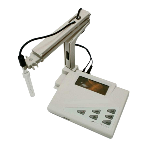
Trans instruments BP3001 User manual
Trans instruments
Trans instruments ELECTROLYZER User manual
Trans instruments
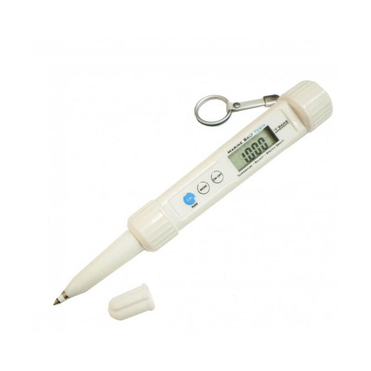
Trans instruments Marine Salt Testa User manual

