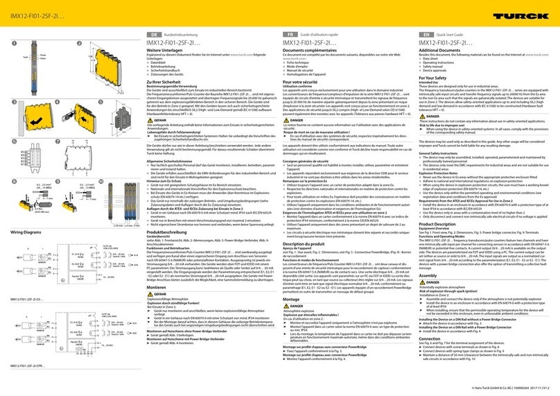
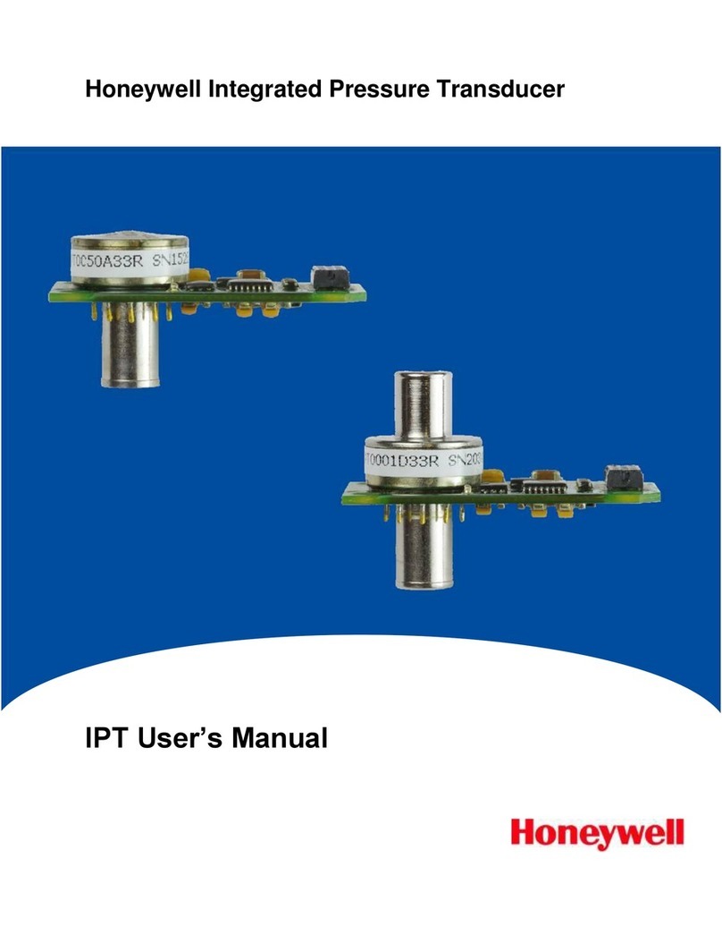
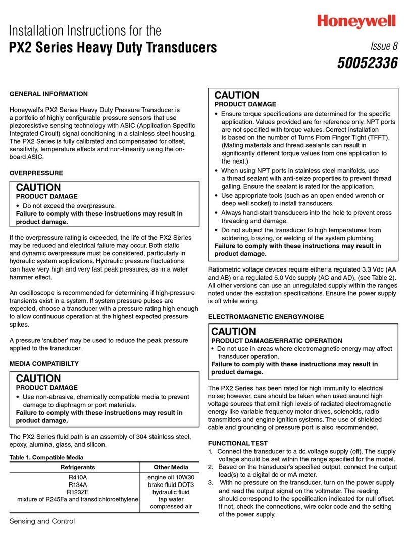
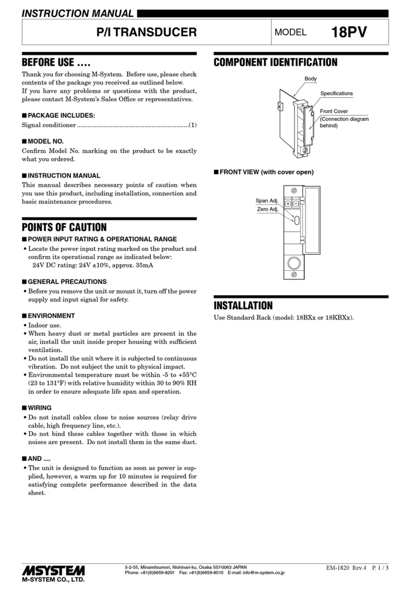
TRANSDUCERS direct TD1A Series User manual

INNOVATIVE SENSORS
FOR INDUSTRIAL AND HOME AUTOMATION
TD1A, 2A, 3A OPTIONS
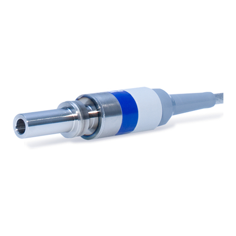
SERIES: TD1A-Rigid Stem
SERIES: TD2A-Stem/Flex
SERIES: TD3A-Stem/Flex with Thermocouple
Introducing the TD1A, 2A, 3A
Series Alloy Fill Melt Pressure
Transducers
FEATURES
• Standard 3.33mV/V, 6 pin Bendix Connector
• 6” Stem (standard), 18” Flex (standard) (TD2A)
• 0.5% or 0.25% Accuracy
• Ranges from 500 to 30,000 psi
• 750º F (400º C) Diaphragm Rating
• Thermocouple Type J (TD3A)
• 80% Output Calibration
• Standard Diaphragm Type 17-4 SS with
Titanium-Aluminum Nitride Coating
• Non-Mercury Alloy Fill
• Connector: 8 pin Screw
• 12” Stem, 30” Flex
• Outputs: 4-20mA, 0-10 VDC

®
INNOVATIVE SENSORS
FOR INDUSTRIAL AND HOME AUTOMATION
SPECIFICATIONS
Mechanical
Ranges 500, 1500, 3000, 5000, 7500
10,000, 15,000, 30,000 psi
Filling Material Alloy (Gallium, Indium, Tin)* No Mercury
Accuracy +/- 0.5% or 0.25% BFSL @ 25°C (77 °F)
Repeatability <0.5% of Full Scale
Over Pressure Capability 1.5 x Full Scale
Mounting Torque 150 Inch-lbs MIN 500 Inch-lbs MAX
Temperature Effects
Maximum Diaphragm temp 400°C (750°F)
Zero/Span Shift (Diaphragm Temp Change) 5 psi / 100°C (212º F)
Maximum Housing Temp 85º C (185º F)
Zero/Span Shift (Electronics Temp Change) 0.04% F.S / º C MAX
Electrical
Outputs 3.33 mV/V (optional 4-20mA and 0-10 VDC)
Supply Voltge 10 VDC for mV/V output, 9-36 VDC for 4-20mA output,
18-36 VDC for 0-10V output
Insulation Resistance 1000 megohms @50 VDC
Zero Output Factory set. You may remove “Z” screw (top of housing) and press button for 3 seconds
to reset zero if necessary (with no pressure applied). Typically this is not necessary since this is
covered when calibrating a new sensor (setting zero and span) with the controller
Internal Shunt Calibration 80% ± 0.2% Of Full Scale
Response Time <30ms
Load resistance 4-20mA = 12VDC <150 Ω / 24VDC <750 Ω
0-10V = >10K Ω
* NOT TO BE USED IN FOOD GRADE APPLICATIONS
ORDERING
Consult factory for further options.
Series
TD2A
TD1A = Rigid Stem
TD2A = Stem Flex
TD3A = Stem Flex T/C
Output
3
3 = 3.33mV/V
4 = 4-20mA
1 = 0-10VDC
Pressure
5M
C = psi
M = psi x 1000
500C
1.5M
3M
5M
7.5M
10M
15M
30M
Accuracy
5
2 = 0.25%
5 = 0.5%
Thread
U
U = 1/2”-20
M = M18 x 1.5
Electrical Connector
6B
6B = 6 Pin Bendix
8T = 8 Pin Threaded
Diaphragm
R
R = 17-4 stainless steel
with Titanium-Aluminum-
Nitride coating
Flex
18
18 = 18”
30 = 30”
REV: 10.21
Specificationsmay change without notice.The informationwe supply is believed to be accurate and reliable as of this printing. However, we assume no responsibility for its use.While we provide application assistance
personally, through our literature and the Transducers Direct web site, it is up to the customer to determine the suitability of the product in the application.
Stem
6
6 = 6”
12 = 12”

®
INNOVATIVE SENSORS
FOR INDUSTRIAL AND HOME AUTOMATION
MECHANICAL INSTALLATION
1. MOUNTING HOLE
All holes must be concentric within 0.002”
AVAILABLE DRILL KITS : Page 4
2. PROTECTIVE CAP
Leave cap on until installation - FRAGILE tip
3.LUBRICATE THREADS with EITHER :
1. NEVERSEEZ by BOSTIK
2. C5A by FELRO
3. MOLYKOTE by DOW CORNING
4. CLEAN HOLE OF ALL PLASTIC MATERIALS
Any residue can damage tip on installation.
AVAILABLE CLEAN KITS : Page 4
5. TRANSDUCER HOUSING (Max Temp - 185ºF)
Install in low vibration area.
MOUNTING BRACKET: TDMP-MTG-BRACKET
1/2-20 UNF-2A (STANDARD)
7.8
-
0
0.05
10.5
10.7
5.44
11.2
26.9
45° ±0.5°
1/2-20UNF-2A
Millimeters
M18 x 1.5
9.8
-
0
0.05
15.5
45°
±0.5°
5.8
14.3
34.3
12.7
M18×1.5-6g
Millimeters
6. MOUNTING TORQUE
MIN 150inch-lbs MAX 500inch-lbs
Install finger tight then turn 1/4 turn with wrench
ELECTRICAL INSTALLATION
1. WIRING DIAGRAM
Depending on connector below :
2. CABLE+GROUND (26AWG, 6WIRE, SHIELD)
Shield may have to be connected to ground in
a high noise environment. Do not connect to
meter.
3. ZERO ADJUSTMENT
To compensate for pressure drift caused by
temp changes. At operating temperature with
no pressure on transducer, adjust the pressure
indicating device to read “0”
4. SPAN ADJUSTMENT
To calibrate readout device to transducer.
Press “CALIBRATE” and adjust reading to read
80% SPAN.
6PIN BAYONET 8 PIN SCREW
LE AD
S IG N A L +
EXC I T A TIO N -
C A L IB R A T IO N
C A L IB R A T IO N
S IG N A L -
EXC I T A TIO N +
C O LO R
R E D
B L A C K
W H IT E
G R E E N
B L U E
O R A N G E
6 P IN
A
B
C
D
E
F
LEA D
E X C ITA T IO N +
S I G N A L +
E X C ITA T IO N -
S I G N A L -
C A L I B R A T IO N
C A L I B R A T IO N
N O T U S E D
N O T U S E D
CO LOR
W H IT E
R E D
G R EE N
B L A C K
B L U E
O R A N G E
8 P IN
A
B
C
D
E
F
G
H
6PIN BAYONET
4-20mA OUTPUT VOLTAGE OUTPUT
0-10VDC
TRANSMITTER - 4-20mA or VOLTAGE
L E A D
S IG N A L +
EXC I TA T I O N -
C A L IB R A T IO N
C A L IB R A T IO N
S IG N A L -
EXC I TA T I O N +
C O L O R
R E D
B LA C K
W H I T E
G R EEN
B LU E
O R A N G E
6 P IN
A
B
C
D
E
F
L E A D
S U PPLY /S IG N A L+
S U PPLY /S IG N A L
N / A
N / A
C A L IB R A T IO N
C A L IB R A T IO N
-
C O L O R
R E D
B LA C K
W H I T E
G R E EN
B LU E
O R A N G E
6 P IN
A
B
C
D
E
F
TRANSDUCER - 3.33 mV/V
TRANSDUCER - 3.33 mV/V

®
INNOVATIVE SENSORS
FOR INDUSTRIAL AND HOME AUTOMATION
DIMENSIONS
7.8
-
0
0.05
10.5
10.7
12.7
5.44
11.2
26.9 34.5
R ig i d s t e m l e n g th
18.5 95.2
38
45° ±0.5°
1/2-20UNF-2A
HEX 15.8
7.8
-
0
0.05
10.5
10.7
12.7
17.5
31.8 95.2
38
5.44
11.2
26.9 34.5
Ri g i d s t e m l e n g th
21
F le x st e m l e n g t h
45° ±0.5°
1/2-20UNF-2A
HEX 15.8
7.8
-
0
0.05
10.5
10.7
12.7
31.8
17.5
38
5.44
11.2
26.9 34.5
R ig i d s t e m l e n g th
13.7 34.8
F le x s t e m le n g th
31.8 95.2
45° ±0.5°
1/2-20UNF-2A
HEX 22.4
T h e m o c o u p l e
9.8
-
0
0.05
15.5
45°
±0.5°
5.8
14.3
34.3
12.7
M18×1.5-6g
49.5
R8.75
57.5
52
2×
6.5
35
12.8
63.25
3
TD3A TD2A TD1A
Optional M18 x 1.5
Mounting Bracket

®
INNOVATIVE SENSORS
FOR INDUSTRIAL AND HOME AUTOMATION
GENERAL OPERATION GUIDES
1. START UP
Before starting the extruder drive, ensure that the extruder is at operational temperature and plastic at tip is mol-
ten. A cold start can literally rip off the fragile diaphragm.
2. REMOVAL
Only remove transducer when barrel is at operational temperature and zero pressure.
Always clean hole of all solids before re-installing.
Check hole dimensions with thread gauge of cleaning kit to ensure proper hole. Hole size at tip can reduce over
time. Always remove transducer before cleaning inside barrel with abrasive cleaner or wire brush.
3. CLEANING TIP
Clean tip lightly with a dry cloth while tip is still hot.
Do not use any sharp tools (screwdriver, chisel, knife, wire brush etc.)
TROUBLE SHOOTING
1. Indicator Full Scale
2. Indicator Unstable Reading
3. Indicator Reads Only “0”
4. Indicates Wrong Pressure
Check Continuity Of Cables
Check Continuity Of Cables
Perform Calibration
If Doesn’t Change - Send Transducer In For Anaysis
Perform Calibration
If Still Incorrect - Send Transducer In For Analysis
HOLE CLEANING KIT
TDMP-1-CLEANKIT
Kit is used to clean transducer hole before insertion to
prevent diaphragm damage.
HOLE CUTTING KIT
TDMP-1-CUTTINGKIT
All the Drills, Reamers and Taps required to drill a
proper hole for standard transducers (1/2-20UNF).
THREAD CLEANERTHREAD CLEANER
TIP CLEANER
THREAD GAUGE
5/16” REAMER 29/64” PILOT DRILL
9/32” DRILL BOTTOM TAP
17/32” DRILL 1/20-20UNF TAP
This manual suits for next models
2
Table of contents
Other TRANSDUCERS direct Transducer manuals
